Information about the manufacturer of the radial drilling machine 2K52
The manufacturer of the radial drilling machine model 2K52 is the Gomel Machine Unit Plant GZSU , founded in 1961.
The developer of the portable radial drilling machine 2K52 is Odessa Special Design Moscow Bureau of Diamond Boring and Radial Drilling Machines .
In 1976-1991, the plant was part of the Moscow machine-tool association "Red Proletary". Currently, OJSC Gomel Machine Unit Plant produces metal-cutting machines and components for them.
Products of the Gomel Machine Unit Plant, GZSU
- 2E52
– portable radial drilling machine Ø 25 - 2K52, 2K52-1
- portable radial drilling machine Ø 25 - 2K522
– portable radial drilling machine Ø 32 - 2K550V
– radial drilling machine Ø 55 - 2T140, 2T125
- vertical drilling machine Ø 40 - GS520
– tabletop drilling machine Ø 16 - GS526U
- universal screw-cutting lathe Ø 500 - GS545
– portable radial drilling machine Ø 45 - GS2112
- tabletop drilling machine Ø 12 - GS2116k
- tabletop drilling machine Ø 18 - 16B20p.061
- apron for screw-cutting lathes - 16B20p.070
— feed box for screw-cutting lathes - UG9321
- 6-position automatic turret head for CNC lathes - UG9326
- automatic 8-position turret head for CNC lathes
2K52 portable radial drilling machine. Purpose and scope
Radial drilling machines model 2K52 were produced until 1990, then significant changes were made to the kinematic diagram of the machine. In particular, the number of teeth in almost all gears was changed, which led to the appearance of a machine with the index 2K522.
The portable radial drilling machine model 2K52 is designed for processing holes in medium and large parts in single, small-scale and mass production.
2K52 drilling machine you can perform: drilling, reaming, countersinking, reaming, threading and boring holes. It can be used most effectively when processing holes located at angles in different planes of large parts in tool, repair, experimental, assembly and production shops.
Operating principle and design features of the machine
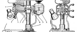
2K52 machine consists of the following main components: base, column, body, sleeve, carriage, drilling head, column clamping mechanism, coolant supply system and electrical equipment.
on the base , and a coolant tank is attached to it at the end.
The column is a steel pipe installed in a plinth on two bearings. The base contains part of the electrical equipment and the column clamping mechanism .
The housing is a cast iron casting of rigid shape and is the base part for assembling the gearbox, the mechanism for moving the housing along the column, and the mechanism for clamping the housing on the column.
Electrical equipment is installed in the housing niche.
On the front side of the case there are control handles for the gearbox, a mechanism for moving the barrel along the column and a control panel.
The sleeve is attached to the body with four clamps. A carriage with a drilling head attached to it moves along the guides of the sleeve The sleeve is rotated around its axis by a handle through a worm gear.
The drilling head is a cast iron casting in which the spindle, feed box and steering device are mounted.
spindle has a wide range of rotation speed control and can be spatially oriented by rotating the sleeve and drilling head.
The machine is equipped with a device for processing holes to a given depth and devices that protect against overloads in terms of torque and axial force. When processing large parts outside the working surface of the plate, the machine is aligned using screw supports. It is recommended to process small parts on a box-shaped table mounted on the table plate.
A distinctive feature of the machine of this standard size is the presence of a rotating column and mounting of the drill head carriage on sleeve guides on rolling bearings, which significantly increases the ease of operation of the machine.
The machine is manufactured for operation in temperate climates, on request for operation in tropical climates, as well as for processing parts in the inch measurement system.
The electrical equipment of the machine can be designed for supply current with a frequency of 50 and 60 Hz and a voltage of 220, 380, 400, 415, 440, 600 V.
On request, the machine is equipped with an electromechanical column clamp, as well as with a system for supplying coolant to the cutting zone.
Machine accuracy class N according to GOST 8-77.
The roughness of the treated surfaces, depending on the work performed, is R = 80-20 microns.
Device and technical capabilities
Overview and technical characteristics of the drilling machine 2m112
2K52 includes:
- T-slot base plate equipped with universal screw fastenings.
- Gearbox.
- Vertical column.
- A movable traverse in which the tool head is located.
- Traverse movement and fixation unit.
- Unit for moving and fixing the tool head.
- Spindle.
- Electric motor.
- A coolant tank that is mounted on a base plate.
- Hydraulic drive of the cooling system.
- Control system.
The massive foundation slab is made of high-quality cast iron, in the bosses of which cavities are provided for mounting the gearbox and the drive of the radial drilling machine. The controls are installed on the front end of the frame.
Technical parameters provide for the movement of the tool head in a special sleeve, which centers the movement of the tool and protects it from chips. Rough movements are carried out using a steering wheel, more precise movements are carried out using dials with divisions, transmitting the movement to a worm gear.
To facilitate rotation of the column, thrust bearings are provided, and the part itself is a hollow thick-walled pipe, inside of which the cooling system drive is located.
The relative position of the sleeve relative to the spindle can be changed by means of adjustable clamps. This guarantees the correct positioning of the 2K52 relative to the workpiece being processed.
Model 2K52-1 differs from the basic one in that the machine column is equipped with an electromechanical locking mechanism, which is used for long-term metal-cutting operations. The drive is also useful if the base on which the 2K52 is installed is insufficiently rigid. In addition, this modification can accommodate an additional, vertically located table.
The working space of the area where it is necessary to drill or drill a hole is limited to the following dimensions:
- When moving the column horizontally – up to 600 mm;
- When drilling in a vertical direction – up to 250 mm;
- Range of horizontal movement of the tool head – 300-800 mm;
- Angular movement of the working tool - ±35°;
- The range of distances from the tool end when drilling is 125-1000 mm.
In order to drill several obliquely located holes, a steering wheel is used, which is fixed during the technological operation. For the convenience of monitoring the progress of the transitions being made, the machine is equipped with emergency lighting of the drilling area with a 24 V lamp.
Characteristics of 2K52:
- The power of the asynchronous reversible electric motor is 1.5 kW.
- The number of discretely variable spindle rotation speeds is 6, from 63 to 1600 min-1.
- Feed limits – 0.125-0.315 mm/rev.
- Tool head approach – rough, precise.
- Sleeve rotation – 0-360°.
- The maximum drilling diameter is 25 mm.
- The largest thread obtained on the machine is M16.
- Accuracy class - N according to GOST 8-77.
- The minimum achievable roughness of the machined contour is Rz.
It is better to purchase a used machine of the considered standard size at specialized enterprises, and after appropriate maintenance - checking the functionality of all control circuits, bearings, and the condition of the mounting bases. It is advisable to buy 2K52 complete with wear parts and specialized installation tools.
General view of the portable radial drilling machine 2K52-1
General view and layout of the radial drilling machine 2k52-1
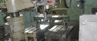
Photo of radial drilling machine 2K52
Photo of radial drilling machine 2K52
3-D model of a 2K52 radial drilling machine from the site asmcg-studio.ru
3-D model of a 2K52 radial drilling machine from the site asmcg-studio.ru
3-D model of a 2K52 radial drilling machine from the site asmcg-studio.ru
3-D model of a 2K52 radial drilling machine from the site asmcg-studio.ru
3-D model of a 2K52 radial drilling machine from the site asmcg-studio.ru
2K522
Sale of radial drilling machines 2K522 from a warehouse (St. Petersburg, Moscow, Chelyabinsk, Kazan) from the manufacturer. Please request price lists with prices for radial drilling machines 2K52-2 in the machine tool department.
| Drilling machine 2K-522-03. | This is interesting: Making a homemade spotter from a battery and a pull-out relay |
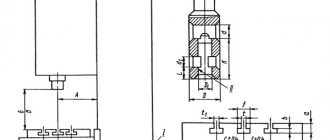
Arrangement of components of the radial drilling machine 2K52-1
Location of the main components of the radial drilling machine 2k52-1
List of components of the radial drilling machine 2K52-1
- Base - 2K52-1.10.00.000
- Column - 2K52-1.20.00.000
- Barrel - 2K52-1.30.00.000
- Sleeve - 2K52-1.40.00.000
- Drilling head - 2K52-1.50.00.000
- Electrical equipment - 2K52-1.80.00.000
Location of controls for radial drilling machine 2K52-1
Location of controls for radial drilling machine 2k52-1
List of controls for radial drilling machine 2K52-1
- Spindle speed switches
- Limit switch pusher “Up”
- Square shank for manual barrel release handle
- The handle for turning on the spindle rotation, mechanical movement of the sleeve along the column and clamping and releasing the barrel on the column
- Spindle speed switches
- Flywheel for moving the drilling head along the sleeve
- Mechanical spindle feed switch handle
- Handle for a-unclamping of the carriage and column (toggle switch 23 in position “A”)
- Manual spindle fine feed handwheel
- Dial lock button
- Handles for turning on mechanical or manual spindle feed
- Button for turning on the dial stop
- Sleeve rotation shaft
- "Emergency stop" button
- Button “Switch off the circuit”
- Toggle switch for turning on local lighting or portable lamp
- Input switch handle
- Column Manual Clamp Handle
- Cooling system control handle
- Limit switch pusher “Down”
- Column release button (toggle switch 23 in position “B”)
- Column clamp button (toggle switch 23 in position “B”)
- Toggle switch for selecting clamp and column release controls
List of graphic symbols on machine plates 2k52-1
Kinematic diagram of the radial drilling machine 2K52-1
Kinematic diagram of the radial drilling machine 2k52-1
The kinematic diagram of the machine contains four kinematic chains:
- spindle rotation chain
- feed chain
- chain of vertical movement of the sleeve
- column clamp chain
Spindle rotation circuit
Spindle rotation from the electric motor M is transmitted through the gearbox, drive shaft U, and bevel gears 39-40; 41-47 to 26-27 spur gear. Mobile blocks 8-7-6-5 and 43-44 speed boxes provide eight stages of spindle speed in the range from 63 to 1600 min.”
CNC drilling machine 2р135ф2: characteristics
- The maximum diameter of parts to be processed should not exceed 35 mm.
- The maximum size does not exceed 24 mm.
- The maximum milling width does not exceed 60 mm.
- The processing process involves 6 tools.
- Spindle speed 12.
- The working surface has the following dimensions - 710x400 mm.
- The spindle speed ranges from 35 to 1600 per minute.
- The number of feeds along the Z axis reaches 18.
- Working feeds along the Z axis range from 10 to 500 mm per minute.
- The table and slide move at speeds of up to 7000 mm per minute, and during the milling process 2200 mm per minute.
- The caliper movement frequency reaches 4000 mm per minute.
- In terms of dimensions, the machine has the following parameters: 1800 mm by 2400 mm by 2700 mm.
Description of the design of the main components of the drilling machine 2k52
Machine base
The base is made in the form of a rigid casting. To increase the stability of the machine, as well as to align the mirror of the plate in a horizontal plane, attached supports are used.
A plinth is mounted on the base, in which a column is installed, rotating on two bearings. The column carries a barrel with a sleeve and a drilling head.
A coolant tank with a pump is attached to the base (supplied upon customer request).
Barrel
The barrel serves as a housing for a number of assembly units: gearbox, shift mechanism, lifting mechanism, clamping mechanism and electrical equipment.
Gearbox
Gearbox for radial drilling machine 2k52-1
Rotation from electric motor 1 (Fig. 10) is transmitted through clutch 2 to shaft I and by gears 5 and 6 to shaft II. Next, gear wheels 3,4,5, 20 with the help of a four-crown block (wheels 16, 17,18,19) and a double-crown block (wheels 12 and 13, shaft III) transmit rotation to gear wheel 10 of the sleeve (through gear II of shaft IV) .
Gear shift mechanism
The mechanism (Fig. 11) is designed to move two- and four-crown gearbox blocks. The spindle rotation speed is set using two handles located on the panel wall, using forks I and 2.
Lifting mechanism
The lifting mechanism (see Fig. 10) is designed for mechanical lifting and lowering of a barrel with a sleeve. The drive is carried out from electric motor I through the included gear 6 with coupling 7 to a bevel pair 14.15. The bevel gear 14 is connected to a nut 9, which, rotating along a fixed screw 8, vertically moves the barrel up and down.
For manual lowering of the barrel, a spring-loaded conical wheel is provided, the shank of which is located on the front wall of the barrel. A conical wheel is used in the case of a horizontal spindle to facilitate alignment to a given coordinate and mechanically lifts the barrel above the given coordinate and then lowers it manually.
The lifting mechanism is equipped with a safety nut in case nut 9 wears out.
Clamping mechanism
The mechanism is designed to clamp the barrel on the column. Clamping - the barrel is released using a handle located on the front panel of the barrel. The handle acts on the ring rack 4 (Fig. 12), which rotates the gear shaft 3, which has an eccentricity, under the influence of which the barrel terminal is tightened.
Sleeve
The sleeve (Fig. 13) is attached to the barrel body and is centered on it by a part that is also a worm wheel for turning the sleeve.
The sleeve is rotated manually with a handle.
A torque overload safety device is mounted on shaft 4, set at the factory to a torque of 90 Nm.
When overloaded, the device trips, as indicated by:
- click;
- stopping spindle rotation under load (without applying load, the spindle rotates);
- facing the pusher 7 with the coupling half 3 (with the casing removed).
Bringing the machine into working condition after the safety device has been activated is done in two ways:
- sharp rotation of the spindle manually in the direction opposite to the rotation of the spindle at the moment of operation. The click and engagement of the pusher 7 with the coupling half 3 indicates the activation of the safety device;
- repeated (5-6 times) reversing the rotation of the machine spindle at n = 1600 rpm.
ATTENTION! Adjusting the safety device mechanism in order to increase the actuation force is unacceptable, as it leads to machine failure.
If the safety device operates again, it is necessary to stop the spindle and eliminate the causes of excess torque.
Carriage
The carriage (Fig. 14) is designed for attaching and moving the drilling head along the sleeve. The head is secured to the carriage by three bolts inserted into the annular T-shaped groove. The drilling head is rotated manually when the bolts are released.
The carriage moves along the sleeve on two bearings I and 2. The carriage is clamped to the sleeve by an eccentric 3, which acts on the rod 6 and the clamp 7.
When clamping the carriage on the sleeve, handle 5 turns on microswitch 4, which closes the electromechanical clamping circuit of the column.
Drill head
The drilling head consists of a spindle drive, a feed box, a feed mechanism, a steering device and a feed switching mechanism.
Spindle drive
The drive (Fig. 15) is a mechanism that transmits rotation from the drive shaft to the spindle and feed box through bevel wheels 6, 11 and cylindrical wheels 3 and 4.
The mechanism consists of two shafts: horizontal 12 and vertical 5. The horizontal hollow shaft is mounted on two supports and is equipped with teeth at the left end that ensure engagement with a bevel gear installed in the carriage. The drilling head moves when the flywheel rotates through gears 8,9,10, pinion shaft 7, wheel I and rack 2.
Machine spindle
Spindle of radial drilling machine 2k52-1
The spindle (Fig. 16) is designed to transmit rotation to the tool installed in its cone. The spindle is mounted on two radial bearings 4 of high accuracy class. The axial load on the spindle is perceived according to the direction by one of two thrust bearings 3.
Feed mechanism
The feed box provides three mechanical feeds - 0.215 mm; 0.2 mm and 0.315 mm.
The feed mechanism consists of a worm 6 (Fig. 17), which receives either mechanical rotation from shaft 3 or manual rotation from the fine manual feed flywheel 7. The worm engages with the worm wheel of the steering gear shaft.
If a fine manual feed is required, the feed handle is set below a feed of 0.2 mm/rev, which corresponds to the neutral position (the “Fine manual tool feed” symbol).
The machine has a safety device against axial force overload. When overloaded, the spring-loaded coupling half 2 slips along the cams of the stationary coupling half I.
The axial play is adjusted by nut I. Pin 6 is a rigid stop that limits the spindle travel in its extreme positions.
The rack of the spindle sleeve 2 is in constant engagement with the rack and pinion gear of the steering gear shaft.
The spindle is equipped with a shockless knockout device for removing the tool from the conical hole. The tool is removed under the action of cam 5 on its shank in the uppermost position of the spindle with pin 6 extended to the extreme left position.
The safety device mechanism in the feed chain is configured to operate when the maximum permissible feed force (5000 N·s) is exceeded.
If, when working under load, the feed is repeatedly switched off due to the operation of the feed chain safety device, it is necessary to stop the spindle and eliminate the causes of excess axial force.
Steering device
The device (Fig. 18) is a gear shaft 7, rotating with the gear coupling 8 engaged, carrying a worm wheel 6 and a rack and pinion gear that meshes with a rack cut on the spindle sleeve. In addition, on the same shaft there is a spiral spring 5 that balances the spindle.
Manual feed of the spindle is carried out by rotating the handles 9 with the gear coupling 8 disconnected.
To turn on the mechanical feed, handles 9 are pulled towards themselves. This engages a gear coupling, which transmits torque from the worm wheel to the rack and pinion gear, which in turn communicates axial movement through the rack to the sleeve with the spindle.
To turn off the feed, you need to move handles 9 away from you. The feed can also be switched off using the hard stop 4.
When working with a rigid stop, dial 2 sets the drilling depth and button I is engaged with the dial. When the specified depth is reached, the dial with pin 3 touches the stop 4 and the feed is switched off by the safety device.
ATTENTION! When replacing the spindle balancing SPRING, as well as during the process of assembling the steering wheel, it is necessary to preload the spring. To do this, you need to turn the handles two full turns relative to the housing in which the spring is installed. The spindle must be in its highest position.
Are you here
Radial drilling machine model 2K52,2K52-1 designed for drilling work in medium and large products. You can also perform other work on it:
- Countersinking;
- Reaming;
- Deployment;
- Threading
It is used in small-scale and mass production.
Controls of radial drilling machine 2K52,2K52-1
- Switching spindle head speeds;
- Limit switch pusher;
- Manual lowering of the barrel;
- Handle for turning on the spindle head, moving the sleeve and clamping and releasing the barrel;
- Switching spindle head speeds;
- Drill head movement;
- Mechanical spindle feed switch handle;
- Handle clamp carriage and column;
- Fine spindle feed manually;
- Fixation of the limb;
- Handle for turning on mechanical or manual feed of the spindle head;
- Turning on the dial stop;
- Sleeve rotation shaft;
- "Emergency stop";
- “Switching off the circuit”;
- Turning on local lighting;
- Input switch handle;
- Column manual clamp handle;
- Coolant control handle;
- Limit switch pusher;
- Column expansion;
- Column clamp button;
- Selecting controls for clamping and releasing the column
Design of radial drilling machine 2K52,2K52-1
- Base;
- Column;
- Barrel;
- Sleeve;
- Drill head;
- Electrical equipment
Kinematic diagram of the radial drilling machine 2K52
Base of radial drilling machine 2K52,2K52-1
The base is a rigid casting on which the plinth in which the column is installed is mounted. On the column there is a barrel with a sleeve and a drilling head.
On the base there are attached supports that serve to increase stability and align the surface of the slab in a horizontal plane.
Barrel of radial drilling machine 2K52,2K52-1
The barrel is a housing for the following assembly units: gearbox, switching mechanism, clamping mechanism, lifting mechanism and electrical equipment.
The rotation of the gearbox is carried out from electric motor 1 through clutch 2 and gears 5 and 6. Next, gears 3, 4,5,20 with the help of a moving block (wheels 16, 17,18,19) and block (wheels) 12 and 14 torque transmitted to gear 2 sleeves.
The speed switching mechanism of the drilling machine is designed to move two movable blocks using two handles located on the panel, using forks 1 and 2.
The lifting mechanism of the drilling machine is designed to lower and lift the barrel with a sleeve. The movement is carried out from electric motor 1 through gear 6 with clutch 7 to bevel gear 14.15. Bevel gear 14 is connected to nut 6, which, moving along screw 8, moves the barrel.
Drilling head for radial drilling machine 2K52,2K52-1
The drilling head includes the following assembly units: spindle drive, feed box, feed mechanism, steering device and feed switching mechanism
The machine spindle drive transmits torque from the drive shaft to the machine spindle through bevel gears 6, 11 and cylindrical gears 3 and 4.
The drilling head is moved using a flywheel through gears 8, 9 and 10, as well as a pinion shaft 7 and rack 2.
The machine spindle is mounted on two radial bearings and transmits torque to the cutting tool installed in the housing.
Operating procedure on the 2K52-I machine
Setup, adjustment and operating mode
After installing the machine, pay attention to its stability and, if necessary, secure the base (for heavy-duty operation).
Clamping of the sleeve on the barrel and the drilling head on the carriage is carried out manually, therefore, before each change in the position of the sleeve and head, they should be wrung out, and after turning, a full clamp must be performed.
Due to the design features of the 2K52-I machine (portable type), which is usually installed without rigid fastening, the cutting modes on it are assigned lower compared to stationary type machines.
The choice of cutting modes is made depending on the material being processed and the diameter of the cutting tool. The feed box handle is set to the position corresponding to the selected mechanical feed. Select the required rotation speed using two handles located on the front side of the barrel, in accordance with the plate.
ATTENTION! You can switch the rotation speed and feed rates only when the spindle is stopped.
When drilling, pay attention to the correct sharpening of the drill, since processing with a tool with incorrect sharpening significantly increases the feed force and reduces the life of the spindle bearings.
The required depth of processing is set and measured along the dial of the steering device using handles.
Regulation
During the operation of the machine, there is a need to regulate its individual components to restore their normal operation. The design of the machine provides the ability to regulate individual elements, the parts of which wear out during operation.
The barrel clamp on the column is adjusted by turning nut 1 (see Fig. 12) to an angle corresponding to thread wear, and then locking nut 2.
The clamp is considered sufficient if the barrel does not rotate on the column under a force of 1000 N at the end of the sleeve.
The clamping of the carriage on the sleeve guides can be adjusted by turning the eccentric shaft acting on the sleeve 3 (see Fig. 14), rod B and clamp 7. The clamping of the carriage is considered sufficient if it cannot be moved from its place under a force of 2500 N.
If it is necessary to adjust the gap between the prismatic guides of the sleeve and the carriage, release the clamps of the eccentric axes I and II and turn these axes to set the required gap (up to 0.05 mm). In this case, the ease of movement of the carriage with the head along the sleeve should not be impaired. After completing the adjustment, tighten the eccentric axle clamps with the screws.
To facilitate the effort of moving the carriage along the sleeve guides, bearings are installed on it, with the help of which the carriage is suspended in relation to the sleeve guides. The adjustment is carried out by turning the torsion eccentric until a gap begins to appear between the front guide of the sleeve and the carriage.
Increased axial play of the spindle is eliminated by tightening the nut, access to which is possible after removing the spindle from the drilling head housing.
The safety clutch against overload in terms of axial force is adjusted using two nuts 5 (see Fig. 17), which tighten the spring 4. The nominal axial force is achieved by adjusting the modes, and under the modes specified in section 10.3, the clutch ensures the transmission of an axial force of 7500 ± 1000 N (no actuation—the cams of coupling half 2 slipping relative to the cams of coupling half I—does not occur).
Limit permissible operating modes
Material - steel 45, GOST 1050-74 Machining diameter - 25 mm Tool - drill 25 mm Tool - drill 25-3, GOST 10903-77
Spindle speed - 160 rpm Feed - 0.125 mm/rev Cutting speed - 14.2 m/min Spindle torque - 110±10 Nm Axial cutting force - 7500±1000 N
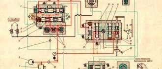
Electrical equipment and electrical circuit of the radial drilling machine 2K52-1
Electrical diagram of the radial drilling machine 2k52-1
List of elements of the electrical circuit of the radial drilling machine 2k52-1
Electrical equipment (with the exception of a few devices) is mounted on the control panel on the rear side of the machine barrel.
The machine is equipped with one three-phase squirrel-cage asynchronous electric motor with a power of 1.5 kW to drive the spindle and move the barrel. By special order, an X14-22M electric pump and an electromechanical clamping head can be installed.
The machine can use the following AC voltages:
- power circuit (50, 60 Hz) ~ 220, 380, 400, 415, 440 V;
- control circuit 50, 60 Hz ~ 110 and 220 V;
- local lighting circuit 50, 60 Hz ~ 24 V;
- signaling circuit 50, 60 Hz ~ 5 V.
Description of the operation of the electrical circuit
Work on the 2K52-1 machine without mechanized column clamping and cooling should begin in the following order:
- set the control handle to the neutral position;
- turn on the lever of the input circuit breaker F1; press the pusher of button S2 to activate the electrical control circuit of the machine. At the same time, the green HI lamp “The machine is ready for operation” lights up. Remember that the machine will not turn on if the control handle is in the working position);
- By turning the handle of the command device, turn on the M2 electric motor that drives the spindle and moves the barrel. The spindle rotation stops (or the barrel moves) when the control device returns to the neutral position.
Switching on, switching off and reversing the electric motor is carried out by the handle of the command device.
To emergency stop the machine, press the red pusher button s1 or turn off the input switch F1. At the same time, lamp H1 goes out.
When installing an electric pump on a machine, it is turned on by turning the lever of the automatic switch F2 to position “I”. When installing a mechanized clamping head, clamping and pressing of the column can be carried out by pressing the pushers of the S7 and S10 buttons located on the control panel, or by moving the handle on the machine carriage.
To select the clamping and spinning controls, use the S9 toggle switch. The duration of clamping and spinning is determined by the time for which time relays K6 and K7 are adjusted. The relays are adjusted so that the opening time is slightly longer than the closing time. The column clamping time is approximately 2-3 s.
Attention! It is impossible to adjust the time delay if the relay is in working condition.
The machine is equipped with a local lighting lamp NKS01x100/P20-0.5. Additionally, an X2 plug connector is provided for connecting a portable lamp.
Electrical diagrams of machine connections are shown in Fig. 20-26.
Electrical protection system and safety measures
Protection of electric motors and transformers from short circuit currents is carried out by automatic switches, protection of control and lighting circuits by fuses. Protection of electric motors from long-term overloads is carried out by thermal relays.
The machine is grounded by connecting a protective wire to a special grounding screw, securely connected to the workshop grounding loop.
It must be remembered that when the input circuit breaker is turned off, its clamps and the input terminal set X6 are under mains voltage.
Technical characteristics of the radial drilling machine 2K52-1
| Parameter name | 2K52-1 | |
| Basic machine parameters | ||
| Machine accuracy class | N | N |
| The largest nominal drilling diameter in steel is 45, mm | 25 | |
| Range of cut threads in steel 45, mm | M16 | |
| Distance from the spindle axis to the guide column (spindle overhang), mm | 300…800 | |
| Maximum horizontal movement of the drilling head along the sleeve, mm | 410…900 | |
| The smallest and largest distance from the end of the spindle to the plate, mm | 125…1000 | |
| Maximum vertical movement of the hose along the column (installation), mm | 625 | |
| Maximum axial movement of the spindle quill (spindle stroke), mm | 250 | |
| Angle of rotation of the sleeve around the column, degrees | 360 | |
| Slab surface size (width length), mm | 800 x 630 | |
| Spindle | ||
| Spindle end designation according to GOST 24644-81 | ||
| Spindle direct rotation frequency, rpm | 63…1600 | |
| Number of direct rotation spindle speeds | 8 | |
| Limits of working feeds per spindle revolution, mm/rev | 0,125; 0,2; 0,315 | |
| Number of working feed stages | 3 | |
| Maximum permissible torque, Nm | 90 | |
| Maximum feed force, kN | 5 | |
| Column rotation clamp | Manual / electric fur | |
| Column Sleeve Clamp | Manual | |
| Drill head clamp on sleeve | Manual | |
| Electrical equipment. Drive unit | ||
| Number of electric motors on the machine | 2/ 3 | |
| Main motion drive electric motor M2, kW | 1,5 | |
| Column clamping motor M3, kW | ||
| Coolant pump electric motor M1, kW | 0,125 | |
| Total power of installed electric motors, kW | ||
| Dimensions and weight of the machine | ||
| Machine dimensions (length width height), mm | 1760 915 1970 | |
| Machine weight, kg | 1250 |
- Radial drilling machines 2K52-1 and 2K52T-1. Operating manual, 1987
- Barun V.A. Working on drilling machines, 1963
- Vinnikov I.Z., Frenkel M.I. Driller, 1971
- Vinnikov I.Z. Drilling machines and work on them, 1988
- Loskutov V.V Drilling and boring machines, 1981
- Panov F.S. Working on CNC machines, 1984
- Popov V.M., Gladilina I.I. Driller, 1958
- Sysoev V.I. Handbook for a Young Driller, 1962
Bibliography
Related Links. Additional Information
- Classification and main characteristics of drilling-milling-boring group of machines
- Selecting the right metalworking machine
- Machine repair technology
- Methodology for checking and testing drilling machines for accuracy and rigidity
- Directory of drilling machines
- Manufacturers of drilling machines in Russia
- Manufacturers of metal-cutting machines
Home About the company News Articles Price list Contacts Reference information Interesting video KPO woodworking machines Manufacturers
Unit differences
Design features include:
- It is easy to choose a model with different energy ratings for connecting to the network: standard 220, industrial 360 and non-standard 600 volts.
- The spindle rotates over a wide range.
- The system control is located on the front side of the device, this allows you to quickly switch between different options.
Technical characteristics of the unit:
- Weight is 1 ton 250 kilograms.
- Dimensions: length – 1 meter 76 centimeters; width – 92 cm; height – 1 meter 96 centimeters.
- The power of the main engine for operation is 1.5 kW.
- The cooling system is powered by a pump whose power is 0.125 kW.
- The drilling diameter has a limit; it is 3.5 centimeters.
- The spindle head moves along the sleeve within the range of 40–90 centimeters.
- The machine rotates with a frequency of 60 to 1.6 thousand revolutions per minute.
- Speeds for work: 6.
- The number of working feed stages is 3.
- Work table: 80 cm long and 63 cm wide.
The device rarely breaks down, so repairs are an infrequent task. The unit easily adapts to the dimensions of the room; the unit does not require special lighting or ventilation.
Mechanical components are used to brake and stop the spindle head.
The machine is easy to use, despite its apparent complexity. Before starting work, you should read the instructions for use.