Information about the manufacturers of the TV-16 lathe
The educational screw-cutting lathe TV-16 has been produced in the USSR since the 50s of the last century and, at present, their production has been discontinued at all enterprises.
Several factories and educational institutions were involved in the production of the TV-16 screw-cutting lathe:
- Production association Start , Penza region, Zarechny. Model TS-1
- Machine-building plant named after. S.M.Kirova (PO Box 116) , Alma-Ata.
- Alma-Ata Machine Tool Plant named after. 20th anniversary of October in Alma-Ata.
- Kobrin Tool Plant - Kobrin, Belarus.
- Dubno Foundry and Mechanical Plant - Dubno, Rivne region, Ukraine.
- Ural Machine-Building Plant named after. K.E.Voroshilova - Uralsk, Kazakhstan.
- Irkutsk Mechanical Plant - Irkutsk.
- Industrial College - Izhevsk.
- Technical School No. 37 - Vitebsk, Belarus.
All machines produced by these enterprises were identical and differed mainly only in the form of casting the beds.
Safety precautions
The machine can only be serviced by an employee with the appropriate competencies who can understand the technical intricacies of the equipment and prevent accidents from occurring.
And in order to prevent them from appearing at all, you must follow the following rules:
- It is prohibited to clean or lubricate machine elements during operation.
- After completing work on the machine, you need to turn it off and wait until turning is completed.
- The workplace requires good lighting.
- If problems arise while using the TV-16 metal cutting machine, you should immediately stop working on it and contact a specialist.
- If an accident occurs, it is necessary to de-energize the machine by turning it off from the power supply.
Following these simple rules will help ensure safe operation of the machine.
TV-16 Tabletop screw-cutting lathe. Purpose, scope
the TV-16 lathe was based on the Czechoslovak screw-cutting lathe TOS MN-80 a .
The TV-16 lathe is a desktop universal screw-cutting lathe and is intended for all kinds of turning work in workshops of schools for polytechnic training.
The main purpose of the machine was to teach turning in schools, vocational schools, and technical schools.
Operating principle and design features of the machine
the TV-16 desktop screw-cutting lathe produced by the Machine-Building Plant named after. S.M.Kirova , Alma-Ata.
The TV-16 desktop screw-cutting lathe has a simplified design:
- There is no gearbox - spindle speeds are switched by transferring belts between pulley tracks;
- There is no feed box - the feed speed or pitch of the thread being cut is set by a set of gears in the guitar;
- There is no drive shaft - the mechanical feed of the caliper is provided only by the lead screw.
Despite the stripped-down design, the machine can perform the following types of metal turning:
- Grooving and boring of cylindrical and conical surfaces
- End trimming
- segment
- Metric thread cutting
- Drilling and a number of other works
Main technical characteristics of the TV16 machine
- The largest diameter of a Disk type product installed above the frame is Ø 160 mm;
- The largest turning diameter above the upper part of the support is Ø 90 mm;
- The diameter of the hole in the spindle is Ø 18 mm;
- Distance between centers - 250 mm;
- The longest turning length is 250 mm;
- Electric motor power - 0.4 kW;
- Supply voltage ~ 380/220 V.
The machine is driven from an asynchronous electric motor ~380 or 220V through a 2-stage counter-drive pulley and a 3-stage spindle pulley. By transferring V-belts, you can reduce the spindle speed and obtain one of the 6 speeds necessary for tapping, as well as for heavy work that requires increased torque. Higher spindle speed is used for finishing work. The direction of spindle rotation is determined by the motor.
The spindle of the TV-16 lathe receives 6 stages of rotation (160, 250, 400, 630, 1000, 1600 rpm) from the machine drive.
The front end of the spindle of the TV-16 tank has an M39x4 thread, so to install a lathe chuck on the spindle you need an intermediate flange (also called a plan washer) (see the article Lathe chucks). The standard chuck for the TV-16 machine is Ø100 mm.
- The front end of the spindle is M39 x 4 mm;
- The internal (tool) cone of the spindle is Morse 3 ;
- The standard diameter of the lathe chuck is Ø 100 mm;
- The diameter of the through hole in the spindle is Ø 18 mm;
- Spindle speed limits per minute (6 steps) - 160, 250, 400, 630, 1000, 1600 rpm;
- The largest diameter of the rod is Ø 17 mm;
- Spindle braking - no ;
- Spindle reverse - reverse the electric motor using a three-pole, two-way package switch.
From the spindle the movement is transmitted to the guitar, and from the guitar to the lead screw.
- Limits of longitudinal feeds - 0.01..0.15 mm/rev (18 steps);
- Cutable metric thread with pitch - 0.2..3.0 mm (18 sizes);
Where to buy and what to look for when choosing
Since the machine has been discontinued, buy it only from the reservation of some enterprise, or from private individuals. In any case, when purchasing this used for a home workshop, you should take a number of the following measures:
- Check the serviceability of the machine on site with the current owner.
- Assess the condition of the parts.
- When purchasing, it is recommended to go through all the parts to look again and assess their condition.
buy such equipment on Avito for around 20,000-40,000 rubles. And most often it is taken for personal use, for small turning workshops or to meet the needs of a car service center.
Photos of the TV-16 screw-cutting lathe from different manufacturers
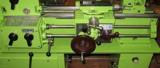
Photo of the TV-16 lathe of the Almaty plant named after. S.M.Kirova
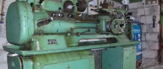
Photo of the TV-16 screw-cutting lathe
Photo of the TV-16 lathe of the Almaty plant named after. S.M.Kirova
Photo of the TV-16 lathe of the Almaty plant named after. S.M.Kirova
Photo of the TV-16 lathe of the Almaty plant named after. S.M.Kirova
Photo of the TV-16 lathe "MINVUZ" Vitebsk
Photo of the TV-16 lathe "MINVUZ" Vitebsk
Photo of the TV-16 lathe of the Kobrin tool plant
Photo of the TV-16 lathe of the Kobrin tool plant
Photo of the TV-16 screw-cutting lathe
Photo of the TV-16 screw-cutting lathe
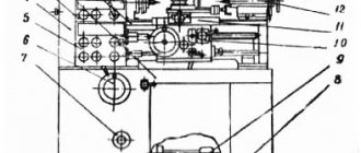
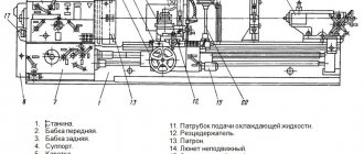
Location of the components of the TV-16 screw-cutting lathe
Location of the components of the TV-16 screw-cutting lathe
Specification of components of the screw-cutting lathe TV-16
- bed;
- headstock;
- machine drive;
- feed mechanism;
- apron;
- caliper;
- tailstock;
- table;
- electrical equipment;
- accessories and tools.
Location of controls for the TV-16 screw-cutting lathe
Location of controls for the TV-16 screw-cutting lathe
Specification of controls for the TV-16 screw-cutting lathe
- Belt tension and release handle for switching spindle speed
- Input switch
- Push button station
- Handle for clamping a bar with a collet clamp
- Bit handle for changing feed direction
- Handle for securing the tool holder
- Handle for turning on the uterine nut
- Handles for moving the upper slide
- Handle for securing the tailstock quill
- Handwheel for moving the tailstock quill
- Tailstock lateral offset screw
- Handle for securing the tailstock to the bed
- Handle for securing the caliper to the frame
- Handle for moving the cross slide
- Handwheel for longitudinal movement of the caliper
- Screws for adjusting the gap in the upper slide guides
- Screws for adjusting the gap in the direction of the cross slide
- Screws to secure the housing to the tailstock plate
- Screws for adjusting the gap in the carriage guides
- Screw for securing the spindle intermediate shaft housing rod
- Machine Ground Screws
Table of threads and feeds of the TV-16 screw-cutting lathe
Table of threads and feeds of the TV-16 screw-cutting lathe
Design features of the headstock and tailstock
The headstock housing of the machine is equipped with a bearing unit into which the equipment spindle is installed. An angular contact bearing is installed at the front end of the spindle, allowing it to absorb axial and radial forces. In order to ensure rotation of the spindle at one of the specified speeds, a V-belt pulley is installed on it. Thus, the rotation from the electric motor is transmitted directly to the machine spindle. The technical capabilities of the machine also allow the rotation of the spindle to be reversed; for this purpose, a bit is installed on its headstock.
The longitudinal movement of the tailstock of a lathe is ensured by prismatic guides along which it moves along the bed. In order for the operator to perform such a movement, the machine is equipped with an eccentric type handle. The characteristics of the lathe suggest the possibility of transverse movement of the tailstock, which must be performed in cases where conical parts are processed on the equipment. Transverse movement of the tailstock is carried out along the bottom plate; for this purpose, a special screw is provided in the design of the machine. In order for a center with a cone to be installed in the tailstock, a special hole is provided in its quill.
The quill is moved manually; for this purpose, a nut with a screw and a flywheel with divisions printed on it are installed in its design. Thanks to the flywheel dial, on which the divisions are marked in millimeter increments, you can move the quill according to the required parameters.
Design of the TV-16 screw-cutting lathe
bed
Bed of screw-cutting lathe TV16
The bed serves to support, secure and interconnect all components of the machine. The bed is cast iron, box-shaped.
The rectangular guide groove 3 (Fig. 1) serves to guide the movement of the caliper, the prismatic groove 1 serves to guide the movement of the tailstock. T-shaped groove 2 is used to attach the tailstock.
On the front side of the frame there is a lead screw 4 (Fig. 2) and a gear rack 5.
The backlash of the lead screw is eliminated with a nut and locknut 6.
The frame, together with the trough 2 on stands 8, is attached to a wooden table with six bolts 3.
Headstock
Headstock of lathe TV-16
Headstock with plain bearings
The headstock (Fig. 3) consists of a body - 1 with a cover - 2, a spindle - 3 and a snaffle - 20 for reversing the feed using a handle - 19,
The spindle with a pulley mounted on it - 4 - is mounted on two plain bearings - front - 9 and rear - 12.
Sliding bearings are liners (bushings) with a conical outer surface. The inserts are cut along three generatrices and cut along the fourth.
The gap between the spindle and the liner is regulated by the axial movement of the latter in the body using the front nut 5 with a felt seal - 15 and the rear - 7.
When tightening nuts 5 and 7, the liners are compressed with some distortion of its inner surface. To eliminate this distortion, screws are provided - 13, which have wedge-shaped heads - 14, inserted into the inclined slots of the liners.
When adjusting, head 14 expands the liner, pressing it tightly against the conical surface of the housing (or to the sleeve - 11 of the rear bearing).
The pulley mounted on the spindle - 4 is secured with a nut - 8 and a stopper - 17.
To lubricate the spindle, two grease nipples are provided - 16 and felt pads - 21.
- The axial play of the spindle is adjusted using nut 8 (Fig. 3). For this purpose, you need to release the locking screw 17 and tighten the nut to select the play, and then lock it again.
- Adjustment of radial play in the spindle bearings is carried out in the following order:
- a) In the front bearing: loosen locknut 6 (Fig. 3), screw 13 and tighten nut 5. Then tighten screw 13 and locknut 6.
- b) In the rear bearing: loosen the locking screw of nut 7 (Fig. 3) and screw 13, and then tighten nut 7 and screw 13. Lock nut 7 again. After adjustment, the spindle should rotate easily by hand. In order to improve the quality of adjustment, it is recommended to scrape the liners along the spindle journals after tightening. The magnitude of the radial clearance is determined as follows: a mandrel with an overhang of about 150 mm is inserted into the conical hole. The measuring rod of the indicator is pressed against the side surface of the spindle neck and by lightly squeezing the extension of the mandrel by hand, the backlash is determined, which should be no more than 0.05 mm.
Spindle bearings for TV-16 lathe
The spindle of the TV-16 machine is mounted on 3 bearings:
- Front spindle support - two bearings No. 36207 GOST 831-54, accuracy class P, size 35x72x17 mm
- Rear spindle support - single-row radial ball bearing No. 206 , OST 6121-39, accuracy class P, size 30x62x16 mm
Technical characteristics of bearing No. 36207
Bearing 36207 is a single row angular contact ball bearing.
Perceives loads of both radial and axial (in one direction) nature. Such bearings are used in high-speed and high-precision components, for example, in the spindles of grinding machines. To ensure high processing accuracy, it is necessary that the spindle have high rigidity. For this purpose, a preload is created. Bearings of this type, lapped together and installed in pairs, are called duplex; they are sold as a set and manufactured with a high degree of precision. They have the designation 436207.
In the Russian Federation it is produced in Samara at SPZ-4 (6-36207 E or L) and in Saratov at 3 GPP (T-36207E5. 6-36207E5, 6-36207L). Prices for Saratov bearings are much higher, as is the quality of the products.
Foreign-made bearings of this type have the number 7207CD.
Dimensions and characteristics of bearing 36207 (7207):
- Inner diameter (d): – 35 mm;
- Outer diameter (D): – 72 mm;
- Width (height) (H): – 17 mm;
- Weight: – 0.289 kg;
- Ball diameter: – 11.112 mm;
- Number of balls in the bearing: – 13 pcs.;
- Outer ring flange diameter: – 60.2 mm;
- Inner ring flange diameter: – 46.9 mm;
- Dynamic load capacity: – 30.8 kN;
- Static load capacity: – 17.8 kN;
- Rated speed: – 12000 rpm.
Diagram of bearing 36207 (7207) of the TV-16 lathe
Adjusting the screw-cutting lathe TV-16
Adjusting the TV-16 lathe
- Screw limiting the gap between the screw and the cross slide nut
- Screw limiting the gap between the screw and the upper slide nut
- Screws holding the cutter
- Screws securing the nut to the top carriage
- Screws for securing the turntable
- Screws limiting the axial play of the screw in the slide
- Nut for tightening spindle bearings
- Spacers
The spindle bearings are tightened using nut 32. Axial play of the spindle is eliminated by creating a preload by selecting spacer bushings 33.
The tension of the V-belt drive belts is adjusted using an eccentric mechanism. The degree of belt tension is regulated by the position of the rod in the eccentric and is fixed with screw 20. The belt tension should not be excessive, but should be such that the belts do not slip on the pulleys. When moving the belt from one pulley to another, you must turn handle 1 and release the belts from tension.
Depending on the required feed, replaceable gears are installed. Gears should be cleaned and lubricated before installation.
Adjustment of the clearances in the guides of the caliper carriage, cross slide and upper slide is carried out using wedges and screws 19, 17 and 16 - (see page 8).
Limiting the gap between the screw and the nut of the cross slide is done with screw 26. To limit the gap between the screw and the nut of the upper slide, loosen the two screws 29 securing the nut and tighten screw 27 until the gap is eliminated, then tighten screws 29 back.
The axial play of the cross slide screw and the upper slide screw is adjusted by selecting the gap between the screw shoulder and the washer using screws 31.
When coning the product in the centers, the transverse displacement of the tailstock body in relation to the tailstock plate is made by screw 11. Screws 18 fix this position of the tailstock (see page 8).
Machine drive
TV-16 lathe drive
Machine drive fig. 4 is mounted in the left cabinet of the table and is driven by an individual electric motor b mounted on a slide 13 attached to the wooden table top with screws 14.
The movement of the electric motor is transmitted to the spindle by two V-belts 7 through an intermediate shaft 3.
The tension of the belt transmitting movement from the electric motor to the intermediate shaft 3 is adjusted by moving it in the electric motor slide. The tension of the belt transmitting movement from the intermediate shaft to the spindle is adjusted using screw 11 and rod 9.
Loosening and tensioning of the belts when transferring the belts is carried out by handle 8 using an eccentric mechanism.
The intermediate shaft 3 is mounted in the housing 1 on roller bearings 4. To adjust the belt tension, the intermediate shaft together with the housing is rotated relative to the axis of the base 2. The rotation is carried out by the handle 8 and is fixed in extreme positions by an eccentric device.
On shaft 3, on one side, there is a 2-speed pulley for connection with the electric motor, and on the other side, a 3-speed pulley for connection with the machine spindle.
Lubrication of the bearings of the shaft 3 and the axis of the base 2 is carried out using grease nipples 12.
Feed mechanism (guitar)
Feed mechanism of lathe TV-16
Feed mechanism of screw-cutting lathe TV16
The feed mechanism is used to transmit movement to the lead screw and adjust the longitudinal feeds for turning and threading.
The feed mechanism is located in box 1 (Fig. 5), attached to the headstock, and is closed by door 2. Lead screw 10 receives movement from the spindle of the machine 8 through the snaffle gear 11 and replaceable gears a, b, c, d.
Replacement gear “a” is attached to the snaffle sleeve 13 with screw 9. Replacement gears “b” and “c” are secured to the guitar with 4 screw 5. After installing the replacement gears to ensure normal tooth engagement, the guitar is secured in the box with 1 screw 6. When setting up the machine for thread cutting, a replaceable gear “d” with a number of teeth of 100 is installed on the lead screw. When setting up the machine for turning, instead of a replaceable gear “d”, a planetary gear is installed on the lead screw. The planetary gear reduces the number of revolutions of the lead screw by 20 times.
To cut threads in a guitar, 4 gears are used - a, b, c, d = 100. The formula for setting a guitar to the required thread pitch is:
T = a/b x c x 3/100
where a, b, c, d are the number of teeth on the guitar's replacement gears. T is the pitch of the thread being cut in mm.
To adjust the longitudinal feeds in the guitar, 3 gears are used - a, b, c and a planetary gear. The formula for tuning a guitar to the required pitch speed:
S = a/b x c x 3/2000
where a, b, c are the number of teeth on the guitar's replacement gears. S—feed in mm per revolution.
Apron
Apron for lathe TV-16
The apron is designed to transmit movement from the lead screw to the caliper. The apron body is attached with screws to the caliper box.
The split nut 3 of the apron is connected to the lead screw.
The nut is turned on and off using handle 5.
When the apron nut is engaged, the longitudinal feed of the caliper will be carried out mechanically from the lead screw. When the apron nut is disconnected, the caliper is moved manually by rotating the handwheel with dial 6, while the caliper is moved through the apron gear 4 and the rack 5 (Fig. 2) on the machine bed.
Caliper
The support is designed to secure and feed the cutting tool. The support consists of 4 main units (Fig. 7): carriage - 1, transverse slide - 2, upper slide - 4, turntable - 3 and tool holder - 5.
The carriage moves in the longitudinal direction along the frame guides, both mechanically from the lead screw and manually using a handwheel located on the apron.
The support is secured to the frame using a screw with a handle - 19.
The cross slide moves perpendicular to the axis of the machine along the upper guides of the carriage. The movement is carried out using a screw - 7 and a split nut - 9, which is tightened with a screw - 10, with which you can eliminate the “backlash” of the screw that occurs as a result of wear on the nut.
The upper slide, mounted on the turntable - 3, can be rotated in both directions and is secured in the required position with two screws - 20. The slide is rotated when turning the cones.
Linear movement of the upper slide is carried out with a screw - 8 and a split nut - 11. The gap between the screw and the nut is adjusted with a screw - 12.
The screws for moving the upper and transverse slides are equipped with dials - 22 and 24.
To adjust the gaps in the guides, use wedges - 13, 15, 17 and adjusting screws - 14, 16 and 18.
Four-sided tool holder - 5 can be rotated 360° with rotation locking at 45°. The tool holder is secured with a handle - 6.
Tailstock
The tailstock (Fig. consists of a body - 1, a plate - 2, a quill - 4, a screw - 3, a nut - 5 and a handwheel with a handle - 12.
The tailstock is manually adjusted along the frame along a prismatic guide and secured in the required position with a groove bolt - 14 and a nut - 6. Quill 4 can extend from the headstock body by 65 mm.
When the handwheel with handle 12 rotates, screw 3, rotating in nut 5, moves the quill. In the required position, the quill is secured with a handle - 13.
For turning cones, it is possible to move the tailstock body transversely - 1 along the plate - 2 by 5 mm forward and backward from the center line.
Movement is carried out using screw - 7.
The tailstock is returned to the center line by aligning the marks on the rear ends of the body and plate.
To lubricate the rubbing surfaces of the tailstock, grease nipples -9 are provided; To lubricate the center, a needle plug is provided - 11, which is placed in a hole filled with oil.
Table
The machine is installed on a wooden table and secured to it with six bolts 3 (Fig. 2). The left cabinet of the table houses the machine drive and electrical equipment.
A push-button station and a packet switch are mounted in the middle part of the table, as well as a drawer.
The right side table has shelves for storing tools and replacement gears.
For safety reasons, limit switches are installed on the door of the left cabinet of the table and on top of the table near the feed mechanism door, which automatically turns off the electric motor when the door is opened.
The desk cabinets and middle drawer are equipped with mortise locks.
Machine lubrication
The reliability of the machine depends to a large extent on the timely lubrication of all its rubbing parts.
The machine should be lubricated according to Table 3 and Fig. 10.
Note: Ball bearings mounted in the machine drive should be cleaned and filled with fresh grease “T” or technical petroleum jelly once a year.
Installation
First of all, you need to drag the machine to where you plan to use it, and only then unpack it. If you order additional packaging, the table is included. In order to achieve precise fixation, the machine must be secured with all six screws supplied in the kit to any wooden surface.
The technical characteristics are already known and then you can start assembling the machine. The first step is to install the drive belt on the drive pulley. Please note that the ground wire must be passed through the holes in the frame intended for this purpose, and then secured with a bolt.
For proper installation, you need to use a level to align the horizontal.
Using fuses, cable wiring is carried out from the distribution panel.
At the last stage, you need to remove grease from all components. After completing this procedure, you need to look at the description of the machine, which indicates the quantity and correct order of arrangement of all parts. The first test is to idle the machine, after which the load can be applied successfully.
Setting up the TV-16 screw-cutting lathe
- Before starting work, you should select the spindle speed according to the plate attached to the headstock. Install the belts onto the corresponding grooves on the pulleys. The V-belt drive is loosened and tensioned using handle 8 (Fig. 4).
- Various feeds and threading are accomplished by installing interchangeable gears a, b, c, d . The selection of gears is made according to the plate attached to the inside of the feed mechanism door. When adjusting for feed, a planetary gear should be installed instead of the replacement gear d .
- Installation of replacement gears is carried out in the following order:
- a) Loosen screw 6 (Fig. 5).
- b) Place gear a and secure it with screw 9.
- c) Place gear b and c and secure them with screw 5.
- d on the lead screw (or install a planetary gear when adjusting for feed). Note: When installing replacement gears, be sure to maintain a lateral clearance between the meshing gear teeth within 0.1 - 0.3 mm.
- e) After installing the replacement gears, secure the guitar with screw 6.
- The machine is started as follows:
- a) Set the switch handle to the “Forward” or “Backward” position (depending on the required direction of spindle rotation). In this case, the arrow marked on the switch handle should be directed to the corresponding inscription on the switch plate.
- b) Press the “Start” button of the push-button station.
Operating rules
When working on equipment, you must adhere to the rules of its operation. First, monitor the condition of the device:
- Perform a thorough cleaning and external inspection of the unit at least once a month.
- Make sure that there is no rust on the surface of the machine. To do this, it is necessary to coat the surface of the connection between the core and the armature with oil, and then wipe it dry so that the oil does not cause gluing of the component parts. Lubrication must be carried out in accordance with the diagram specified in the instruction manual. This requires monitoring the oil level in the system. It is also recommended to use lubricants specified in the service manual.
- In addition to preventive inspections, it is necessary to conduct a thorough inspection and assessment of the condition of the equipment annually, as well as perform routine repairs of components: the condition of the switch, nuts, cleaning the electrical cabinet and other types of work.
- Equipment contacts are made of materials containing silver. Accordingly, there is no need for careful care and adjustment of their condition. In case of any damage, they are replaced with new ones. Performing contact stripping may result in blackening, which may affect the functionality of the equipment.
Performing preventive inspection of joints:
- If the joints are clogged, it is necessary to clean them to ensure that the bolts can turn without tension and the risk of stripping the threads.
- When loosening the bolts, it is necessary to tighten them to prevent rattling of the machine, which negatively affects the accuracy of the correct parameters of the part.
- If traces of use appear on the working surfaces, it is necessary to clean them by removing carbon deposits.
Important! Servicing the equipment is permitted only after disconnecting it from the network.
The implementation and observance of such precautions help to extend the life of the machine and improve the quality of the products turned on it. Improper maintenance of equipment contributes to wear and reduced service life. Therefore, it is important to carry out machine maintenance and cleaning in a timely manner.
Electrical equipment of the TV-16 screw-cutting lathe
Electrical equipment is designed to turn on the machine, reverse the electric motor, protect against short circuits and low voltage in the network, as well as for blocking.
Electrical circuit of the screw-cutting lathe TV16
Group 09 - electrical equipment
The electrical equipment of the TV-16 machine consists of the following devices (see circuit diagram, pages 12 - 13); reversing batch switch “pp” designed to connect the machine to the network, as well as to reverse the electric motor; fuses “p” serving to protect the machine from short circuits; magnetic starter “k” intended for starting and stopping the machine, using the “start” button (1KU) and the “stop” button (2KU).
In addition, the magnetic starter “k” provides zero protection.
Block contacts “1KB” and “2KB”, which turn off the machine when the table door or feed mechanism door is opened. Restarting the machine can only be done with the doors closed. The voltage from the network is supplied to the terminal column to the terminals labeled L1; L2; L3.
For safe operation, the machine must be grounded, for which a block for supplying a grounding wire is provided on the side wall of the table. It must be connected to the ground screws of both panels and to the machine.
Electrical equipment is designed to turn the machine on and off, reverse the electric motor, protect against short circuits and low voltage in the network, as well as for blocking.
The electrical equipment of the machine consists of the following devices (see wiring diagram):
- Electric motor AT-0.25/4, 0.4 kW, n=1420 rpm.
- Magnetic starter “K” type P121A. The magnetic starter starts and stops the electric motor using the “START” (1KU) and “STOP” (2KU) buttons, and also provides zero protection. Note: The magnetic starter coil is supplied at 380 volt line voltage. If the consumer has a line voltage of 220 Volts, then at the consumer’s request the plant can replace the coil with 220 V.
- Fuses “P” type E27 with a 6 A fuse-link are used to protect the machine in case of short circuits in the electrical circuit.
- Batch switch “PP” type PK3-10/N2. The batch switch is designed to connect the machine to the network, as well as to reverse the electric motor.
- Push-button station type KS1-12. The push-button station includes a “START” button (1KU) and a “STOP” button (2KU), when pressed, the magnetic starter is activated and the machine is turned on or off.
- Locking switches 1 KB and 2 KB type KU-01. Locking switches are used to turn off the electric motor when opening the doors of the left table cabinet and the feed mechanism. The machine can only be restarted with the doors closed.
- Terminal set for 3 terminals, type KM 1003, to which mains voltage is supplied.
Electrical circuit operation
Before starting work, the machine must be connected to the electrical network using a packet switch “PP”. The electric motor is started by pressing the “Start” button, which closes the power supply circuit of the magnetic coil in the starter. The coil, under the influence of the current passing through it, attracts the armature core and closes the contacts mechanically connected to it.
The electric motor is stopped by pressing the “STOP” button, which opens the coil circuit and opens all contacts of the starter.
Zero protection of the electric motor is carried out by a contactor coil, which, when the voltage drops to 50 - 60%, disconnects the electric motor from the network.
For safe operation, the machine must be grounded. For this purpose, a block is provided on the side wall of the machine for supplying a grounding wire, which must be connected to the grounding screws of the panels and to the machine.
User manual
The equipment cannot be used or serviced unless you have unplugged it. The machine must be maintained at least once a month. This means that if you decide to purchase such equipment for yourself, you should clean it and inspect it for condition every 30 days.
Also watch the video regarding the operation of TV-16.
Equipment contacts are made from materials that contain silver. Consequently, the operator is not required to carefully care for their condition. There is no need to adjust them either, and if they suddenly wear out, they simply replace them with new ones. If you clean the contacts, blackening will occur, which will undoubtedly affect the performance of the equipment.
To prevent rust on the surface of the machine, the interface between the core and the armature should be coated with machine oil. After this, everything is wiped with a dry cloth so that the oily substance does not provoke gluing of the armature and the core.
Important! The spindle should not create any play during operation.
A complete inspection of equipment and repair of components must be performed at least once a year. Bearing lubricants are changed after 40,000 operating hours. It is better to use lubricant grade 158 TU 38 101320-77. In order for all bearings to function normally, the operator should fill the oil reservoir to 2/3 of its volume.
Advice! Preventive inspection of the unit should be carried out once every 6 months.
Preventive repair of the machine.
In addition to routine inspection, you need to periodically review the condition of the switch, look at the surface of the nuts and other joints to monitor how they are in working condition.
- If the connection points are clogged, you should clean them so that later the bolts can be easily unscrewed without tension and the risk of stripping the threads.
- If the bolts are loose, the operator needs to tighten them, otherwise the machine may rattle, which will affect the accuracy of sharpening or turning the part.
- Carbon deposits and other traces of work should be removed from working surfaces to avoid problems with the machine later.
All these precautions will enable you to significantly increase the service life of such a machine and improve the quality of the parts processed on it.
Important! To avoid problems with damage to wires, it is recommended to clean the electrical cabinet from dust that accumulates there once every 3-4 months.
Main technical characteristics of the TV-16 machine
| Parameter name | MN-80a | TS-1 | TV-16 |
| Basic machine parameters | |||
| Accuracy class | N | N | TU TV-16-0001 |
| The largest diameter of the workpiece above the bed, mm | 160 | 155 | 160 |
| The largest diameter of the workpiece above the support, mm | 90 | 80 | 90 |
| Center height, mm | 80 | 82 | 85 |
| Maximum length of the workpiece at centers (RMC), mm | 300 | 260 | 250 |
| Maximum height of the cutter holder (w x h), mm | 10 x 10 | 10 x 10 | 12 x 15 |
| Height from the cutting surface to the center line, mm | 10 | ||
| The greatest distance from the axis of the centers to the edge of the tool holder, mm | 90 | ||
| Spindle | |||
| Threaded end of spindle, mm | M39 x 4 | M39 x 4 | M39 x 4 |
| Diameter of standard cartridge, mm | 100 | 100 | 100 |
| Diameter of through hole in spindle, mm | 18 | 18 | 18 |
| Diameter and length of the front plain bearing in the spindle, mm | 38 x 50 | 38 x 50 | |
| Centering diameter of the front end of the spindle, mm | 40 x 5 | 40f4 | |
| Maximum rod diameter, mm | 17 | 17 | 17 |
| Spindle bore taper | 1:20 | Morse No. 3 | |
| Number of speed steps for direct spindle rotation | 9 | 6 | 6 |
| Spindle speed, rpm | 150..2000 | 160..1600 | 160..1600 |
| Spindle braking | No | No | No |
| Handle lock | No | No | No |
| Caliper. Submissions | |||
| Maximum longitudinal movement of the caliper, mm | 300 | 260 | 260 |
| Longitudinal movement of the caliper by one dial division, mm | 0,5 | ||
| Lead screw (diameter x pitch) | 16 x 3 | 16 x 3 | |
| Maximum lateral movement of the caliper, mm | 100 | 100 | 100 |
| Transverse movement of the caliper by one division of the dial, mm | 0,05 | ||
| Number of stages of longitudinal feed of the caliper | 18 | ||
| Limits of longitudinal working feeds of the caliper, mm/rev | 0,01…0,15 | 0,01…0,15 | 0,01…0,15 |
| Limits of working cross feeds of the caliper, mm/rev | No | No | No |
| Number of metric threads to be cut | 19 | 20 | 18 |
| Limits of pitches of cut metric threads, mm | 0,2..3 | 0,2..3 | 0,2..3 |
| Limits of pitches of cut inch threads | No | No | No |
| Thread indicator | No | No | No |
| Overload protection | There is | There is | There is |
| Blocking | There is | There is | There is |
| Accelerated movement of the caliper | No | No | No |
| Switching stops | No | No | No |
| Cutting slide (upper slide) | |||
| Maximum movement of the cutting slide, mm | 100 | 100 | 100 |
| Thread pitch of the lead screw of the cutting slide, mm | 1,5 | 1,5 | |
| Thread diameter of the lead screw of the cutting slide, mm | M10 left | ||
| Movement of the cutting slide by one division of the dial, mm | 0,05 | 0,05 | 0,05 |
| Movement of the cutting slide per one revolution of the dial, mm | 1,5 | 1,5 | 1,5 |
| Angle of rotation of the cutting slide, degrees | ±60° | ||
| Tailstock | |||
| Tailstock quill diameter | 20 | 20 | |
| Tailstock quill hole cone | Morse No. 1 | Morse No. 1 | Morse No. 1 |
| Maximum movement of the quill, mm | 80 | 70 | 65 |
| Rule division price, quill movement, mm | 1 | ||
| Limb division price, quill movement, mm | 0,05 | 0,05 | 0,05 |
| Transverse movement of the tailstock, mm | ±5 | ||
| Electrical equipment | |||
| Supply voltage, V | ~380 V/ ~220 V | ~380 V/ ~220 V | ~380 V/ ~220 V |
| Main drive electric motor, kW | 0,37 | 0,25 | 0,4 |
| Dimensions and weight of the machine | |||
| Machine dimensions (length width height), mm | 1170 x 610 x 1310 | 1160 x 540 x 1200 | 1150 x 600 x 1200 |
| Machine weight, kg | 135 | 135 | 180 |
- Passport and manual for the TV-16 table-top screw-cutting lathe. Alma-Ata, 1958
- Passport and manual for the TV-16 table-top screw-cutting lathe. Alma-Ata, 1957
- Acherkan N.S. Metal-cutting machines, Volume 1, 1965
- Batov V.P. Lathes, 1978
- Beletsky D.G. Handbook of a universal turner, 1987
- Denezhny P.M., Stiskin G.M., Thor I.E. Turning, 1972. (1k62)
- Denezhny P.M., Stiskin G.M., Thor I.E. Turning, 1979. (16k20)
- Lokteva S.E. Computer controlled machines, 1986
- Modzelevsky A. A., Muschinkin A. A., Kedrov S. S., Sobol A. M., Zavgorodniy Yu. P., Lathes, 1973
- Pikus M.Yu. A mechanic's guide to machine repair, 1987
- Skhirtladze A.G., Novikov V.Yu. Technological equipment for machine-building industries, 1980
- Tepinkichiev V.K. Metal cutting machines, 1973
- Chernov N.N. Metal cutting machines, 1988
Bibliography
Related Links. Additional Information
- Classification and main characteristics of turning
- Selecting the right metalworking machine
- Multi-start thread. Methods for cutting multi-start threads on a lathe
- Graphic signs for lathes
- Friction clutch of a screw-cutting lathe
- Methodology for checking and testing screw-cutting lathes for accuracy
- Directory of lathe manufacturing plants
- Directory of factories producing metal-cutting machines
- Directory of lathes
- Articles on the topic