Information about the manufacturer of the CNC lathe 16K20F3
16K20F3 lathe - Moscow Machine Tool Plant named after. A.I. Efremova , founded in 1857.
The first universal screw-cutting lathes with a gearbox for the first time in the USSR began to be produced at the Moscow Machine Tool Building named after. A.I. Efremov in 1932 and received the names DIP-200, DIP-300, DIP-400, DIP-500 ( DIP
- Catch up and Overtake), where 200, 300, 400, 500 is the height of the centers above the frame.
As the design of the machines improved, the plant produced more and more modern models - 1A62, 1K62, 16K20, MK6056.
Machine tools produced by the Moscow Machine Tool Plant Krasny Proletary, KP
- 1A62
- universal screw-cutting lathe Ø 400 - 1K62
- universal screw-cutting lathe Ø 400 - 1K62B
- universal screw-cutting lathe with increased accuracy Ø 400 - 1K282
- eight-spindle vertical lathe Ø 250 - 1K620
- universal screw-cutting lathe with variator Ø 400 - 1K625
- lightweight screw-cutting lathe with an increased line of centers Ø 500 - 16A20F3
– CNC lathe Ø 400 - 16B20P
- high-precision screw-cutting lathe Ø 400 - 16K20
– universal screw-cutting lathe Ø 400 - 16K20M
- mechanized screw-cutting lathe Ø 400 - 16K20P
- high-precision screw-cutting lathe Ø 400 - 16K20F3
– CNC lathe Ø 400 - 16K20F3S32
– CNC lathe Ø 400 - 16K20T1
- lathe with operational control Ø 500 - 16K25
- lightweight screw-cutting lathe with an increased line of centers Ø 500 - 162
— universal screw-cutting lathe Ø 420 - 1730
— semi-automatic multi-cutting lathe Ø 410 - DIP-40 (1D64)
- universal screw-cutting lathe Ø 800 - DIP-50 (1D65)
- universal screw-cutting lathe Ø 1000 - DIP-200
– universal screw-cutting lathe Ø 400 - DIP-300
– universal screw-cutting lathe Ø 630 - DIP-400
– universal screw-cutting lathe Ø 800 - DIP-500
– universal screw-cutting lathe Ø 1000 - MK6046, MK6047, MK6048
- universal screw-cutting lathe Ø 500 - MK6056, MK6057, MK6058
- universal screw-cutting lathe Ø 500 - MK-3002
- table lathe Ø 220
Application
To process various parts at industrial enterprises, 16K20FZ lathes, which have the necessary technical characteristics, are widely used. The production of this type of equipment was organized at the Moscow machine tool manufacturing plant in the 1970s, which was supplied to many regions of the country.
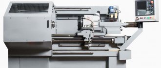
Modern modernized complex 16K20FZ
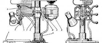
General view of the CNC lathe 16K20F3
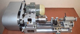
Photo of lathe 16k20f3
Photo of lathe 16k20f3
Photo of lathe 16k20f3
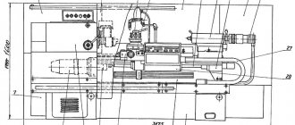
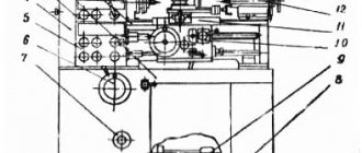
Kinematic diagram of a CNC lathe 16K20F3
Kinematic diagram of a lathe 16k20f3
The main movement is transmitted to spindle VI. The source of movement is the electric motor M1. Automatic gearbox (AKS) 5 with electromagnetic clutches ensures automatic speed switching. The box is connected to the engine and the spindle head by V-belt drives.
Rotation in the headstock from shaft IV is transmitted through gears to shaft V and then by turning on gears or to spindle VI. When the gear pair is turned on, the spindle receives a rotation speed of 35…560 min–¹, and when the gear wheels are turned on – 100…1600 min–¹. Thus, the spindle can receive 18 rotation speeds (9 + 9), but since 6 of them are repeated, it has twelve operating speeds of 35...1600 rpm.
Drives for longitudinal and transverse feed can have two designs: stepper electro-hydraulic (open-loop CNC system) and with adjustable DC electric motors. Feed drives use backlash-free ball gears 9 and 10 with a pitch of p = 10 mm for longitudinal movement and a pitch of p = 5 mm for transverse movement. The longitudinal and transverse movements of the carriage 2 are controlled by feedback sensors 10 and 11, respectively, which rotate from the lead screws through backlash-free gears.
To cut threads according to the program, the machine is equipped with a thread cutting sensor 12 type BE-51. The rotation of the sensor is also carried out through a backlash-free gear drive. The rotation of the tool holder occurs from the electric motor M4 through the gears and, at the initial moment of movement of the coupling M1, shaft VII is fed to the left, the end-face flat-tooth coupling M2 is disengaged, and the tool holder rotates to the desired position, which is controlled by a special block of limit switches 13. Then the direction of rotation of the motor M4 and clutch M1 changes, shaft VII moves to the right, compressing spring 14, and the tool holder is fixed by clutch M2. The processing cycle begins.
Equipment technical parameters
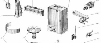
Equipment components
By default, lathes of the 16A20F3 series are equipped with a CNC of the 2P22 series, model 16A20F3S39 is supplied with the NTs-31-02 block. At the same time, the overall dimensions of the equipment are 370 * 170 * 214.5 cm with a weight of 4150 kg. To connect, you will need a three-phase 380 V power line.
Significantly, the modification of the machine changes the maximum permissible size of the part processed above the bed. This parameter can be 40 or 32 cm. The same applies to the cross-section of the workpiece above the caliper, which is 22 or 20 cm. The maximum length cannot exceed 100 cm. It can vary depending on the installed tool head - 90, 75 or 85 cm.
It is also necessary to consider the characteristics of the 16A20F3 lathe with a drive. The most important of them are:
- number of operating speeds – 22;
- speed limits, rpm – from 12.5 to 2000;
- speed range that can be set manually for each row: I – 12.5-200; II – 50-800; III – 125-2000;
- in automatic mode, 9 speeds can be installed;
- automatic switching range - 16;
- the maximum permissible torque is 800 Nm.
Technical characteristics of machine feeds:
- maximum displacement parameters. Along the X axis – 90 cm: along the Z axis – 25 cm;
- thread pitch - from 0.1 to 39.999 mm;
- the range of possible transverse and longitudinal speeds is the same and can vary from 3 to 2000 mm/rev;
- permissible cutter height is 25 mm.
The standard CNC blocks that come with the 16A20F3 lathe have almost the same parameters. The number of controlled coordinates is 2. The discreteness of changing the value for each of them is 0.001 mm. The difference lies in the feedback sensor. The BE178A5 block has expanded functionality.
The video shows an example of the first launch of a machine with a CNC unit.
Front spindle head of machine 16K20F3
Drawing of the front spindle headstock of a lathe 16k20f3 (Fig. 16a)
Installation of the headstock with the spindle axis along the calculated line of the machine centers on the bed is done with two screws.
The headstock lubrication is centralized from a special lubrication station mounted on the base of the machine.
The spindle is mounted in two tapered roller bearings of the Gamay type or domestic No. 3182120 class. "C" and No. 46216 class. "A".
The selection of the radial clearance in the rear bearing and compensation of thermal deformations is carried out under the action of springs 21.
Attention! The Gamay bearing is adjusted at the machine manufacturer's factory and does not require adjustment during operation of the machine.
In machines 16K20FZS5 and 16K20FZS8, a threading sensor I is installed in the headstock.
To constantly sample the backlash in the gearing, gear 6 is constantly pressed by springs 2. The resolution of the sensor is 1000 pulses per revolution and I is zero pulse for the position of the spindle when inserting into the thread when cutting threads in several passes.
Spindle head lubrication is centralized.
Transverse feed drive of a CNC lathe 16K20F3S5
Drawing of the transverse feed drive of the lathe 16k20f3
The support carriage 1 moves along the frame guides, and the slide 2 moves along the carriage guides. From a stepper motor with hydraulic booster 16, mounted on bracket 14, rotation is transmitted to the rolling screw 9 through wheels 17 and 13. To select the gap in the gearing, wheel 17 is shifted relative to wheel 13. The rolling screw 9 is installed in radial bearings 12, the tension in which is created by twelve springs 19 inserted into special bushings 18. The rolling screw is held against axial displacement by thrust bearings 11, the tension in which is created by compression of springs 10. Opening of the joint between the right end of the nut 21 and bushing 20 is unacceptable.
The nut body 6 is rigidly attached to the caliper 1 with a wedge 5. Rigid joining of the nut body 6 with the flange 3 is achieved by grinding the latter.
The selection of the gap and adjustment of the tension in the screw-rolling nut pair is carried out by rotating the half-nut 7 relative to the half-nut 4 using wheel 8, the rotation of which by one tooth relative to the half-nut 7 leads to an axial displacement of 1 μm. The contactless limit switch 15 provides a preliminary signal about reaching the zero position.
Thread cutting is achieved by matching the signals coming from the photoelectric threading sensor 12 (Fig. 2.13) in the spindle head and the signals entering the M2 stepper motor. Thanks to this, the rotation of the spindle is coordinated with the longitudinal movement of the support. Coordination is carried out by the CNC system. In it, a switch is used to adjust the ratio of movements required for a given pitch Рд of the thread being cut. Known design displacements: 1 rev. sp. → Рд mm caliper movements are expressed through the number of pulses; 1000 pulses from the sensor 12 → 100 Rd pulses to the M2 motor (taking into account the discreteness of movements: Rd/0.01 = 100 Rd), that is, 10 pulses from the sensor 12 → Rd pulses to the M2 motor.
The rotation of the faceplate 3 of the six-position tool holder around the horizontal axis (shaft VII) is carried out by an M4 electric motor through gears and a worm gear. In the working position, the faceplate is secured against rotation by a flat-toothed coupling M2. Its engagement, which is prevented by a spring on shaft VII, and disengagement occur due to the helical shape of the teeth of the M1 coupling. At the initial moment of movement of the M1 coupling, shaft VII moves to the left, the M2 coupling is disengaged and the tool holder rotates to the desired position, which is fixed by the limit switches. Then the direction of rotation of the M4 engine and, accordingly, the M1 coupling changes, the spring is compressed by the cams of the M1 coupling half, and the moving part of the M7 coupling half is fixed on its stationary part. The processing cycle begins.
Longitudinal feed drive of a CNC lathe 16K20F3
Drawing of the longitudinal feed drive of the lathe 16k20f3
Longitudinal feed drive - includes a single-stage gearbox, leadscrew supports and a ball screw-nut drive with a nominal diameter of 63 mm, pitch 10 mm. The gearbox has 2 versions: for a hydraulic stepper drive and for installing a DC electric motor. The design allows for the installation of a feedback sensor.
Another version of the machine
CNC turret lathe (TRS) – with expanded functionality (the number of operations performed by this device with a special head has been increased). Using it, you can use different types of cutters in your work and this increases the productivity of machine tools. When working with turning group devices equipped with a CNC module, it is possible to minimize human participation in the technological process.
The main technical difference between the 16k20 machines from the series of screw-cutting lathes and the revolving ones is the absence of a lead screw and tailstock in the revolving ones. But these models have a turret head (a tool is installed in its sockets). You can insert several tools (according to the number of tool holders) into the turret. The workpiece, clamped by a chuck or using a collet clamping device, is processed in several transitions.
The benefit of a turret is obvious if a variety of cutting tools are needed to carry out production operations. Rotating around its axis, the cutters sequentially bring the tools to the part.
Rotary tool holder of machine 16K20F3
Drawing of a rotary tool holder for a lathe 16k20f3
The design of the rotary tool holder is shown in Fig. 2.15. On the output shaft 4 there is a removable tool head (not shown in the figure), connected to the movable coupling half 6 of the flat-toothed coupling. The rotation of the tool holder is carried out through a worm pair 1–2, a cam coupling half 7, the other half 8 of which is rigidly connected to the shaft 4. At the initial moment of movement of this cam coupling, the shaft 4 is fed to the left, while the movable coupling half 6 of the flat-gear coupling moves away from the stationary coupling half 3 and the tool holder begins turning to the desired position, which is determined by pressing the cam 10 on the corresponding limit switch 9. Then the engine is reversed and the coupling half 7 rotates in the other direction, while the coupling half 6 with the tool head is kept from turning by a lock. The cams of the coupling half 7 rest against the cams of the coupling half 8, the spring 5 is compressed and the coupling half 6 is fixed on the teeth of the coupling half 3. The clamping limit switch gives a command, the rotation motor is turned off, and the processing cycle begins.
In the removable tool head, you can install six cutter inserts or three tool blocks, which are adjusted to size outside the machine in special optical devices with adjusting screws in two planes.
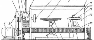
The diagram shows a variant of a mechanized tailstock, in which the quill moves from the electromechanical head of the EG.
Tailstock of machine 16K20F3
Drawing of the tailstock of a lathe 16k20f3
The tailstock has a rigid structure. Using a handle, an eccentric shaft, a clamping bar and a lever system, the tailstock is secured to the frame.
If handle 13, retracted to the rearmost position, does not provide sufficient clamping of the tailstock to the frame, then it is necessary to set the required clamping force by adjusting screws 17 and 23 with lock nuts 13 and 24 released, changing the position of the clamping bar 19.
The quill is moved using an electromechanical head “PRIZ VS05” through a screw, in increments of 5 mm.
The constant clamping force of the part is ensured using disc springs.
Electrical equipment of a CNC lathe 16K20F3
Spindle speed selection
To switch on the appropriate spindle speed, signals are sent to speed code relays. The connection of the code relay contacts is a relay decoder, at the output of which, with the appropriate activation of the code relays, we obtain one of the nine required spindle speeds, with the activation of the corresponding electromagnetic clutch AKS (the order of activation of the electromagnetic clutches is indicated in the table on the circuit diagram of the machine).
When all relays are turned off, a braking command is issued. Spindle rotation in jog mode is possible by turning off all code relays and pressing the jog mode button, which turns on the low spindle speed in the forward direction. Range control is carried out by a limit switch. The main drive electric motor is turned on by sending a command from the CNC device or from the machine control panel to the intermediate relays and turning on the corresponding contactor.
The purpose and designation of the devices that carry out the work of the spindle are indicated in table No. 5.
Tool position selection
The machine provides the ability to install 6 or 8 position tool holders - a turret head.
The tool holder is rotated to the required position by sending a signal to the tool holder tool change relay and the tool position code relays with the electric motor or hydraulic motor turned on. The scheme is based on the coincidence of the specified tool position from the CNC device with the position determined by the limit switches for monitoring the position of the toolholder.
If the position matches, the coincidence relay is turned on, which gives a command to reverse the toolholder.
At the end of the toolholder rotation cycle, the feedback relay is turned on, giving a signal to the CNC device to continue processing the program.
The symbol and purpose of the devices according to the electrical circuit that perform the work of the tool holder are given in Table. 6.
Turn on cooling
In automatic mode, the cooling motor operates when CNC signals are sent to an intermediate relay, which turns on the cooling motor contactor.
During the cutting process, it is possible to start cooling with a switch from the machine control panel when the main drive is turned on.
The symbol for the purpose of the devices involved in the cooling operation is given in Table 7.
Operation of lubrication units
The lubrication motor is turned on each time the machine is initially started and remains on for the time required for lubrication. When the machine operates for a long time, the lubrication cycle is set by the corresponding relays with the required time delay for lubrication and pause.
The machine provides the ability to turn on the lubrication during a pause - using a push button without disturbing the lubrication cycle.
The symbols of the devices involved in the operation of the lubrication unit are given in Table 7.
Clamping and releasing the chuck, supplying and removing the quill
The machine can be equipped with electromechanical devices “Priz” for supplying and retracting the tailstock quill and clamping and releasing the part in the chuck.” Control is provided by foot pedals; each of which has its own specific function, see features. 16K20F.390.000 E3 and devil. 16K20F.290.000 E4 sheet 1.
Locks
The following locks have been implemented in the electrical circuit of the machine:
- prohibiting the inclusion of the main drive electric motor simultaneously in the forward and reverse directions. For this purpose, the breaking contacts of contactors RK5 and RK4 are used in the coil circuits of these contactors;
- prohibiting the activation of the toolholder electric motor simultaneously in the forward and reverse directions. For this purpose, the breaking contacts of contactors RK7 and RK8 are used in the coil circuits of these contactors;
- restriction of movement of the carriage and support to the extreme limit positions. Retraction of the support carriage from its extreme positions is carried out using the corresponding buttons in manual mode (see the circuit diagram of the machine);
- prohibition of simultaneous activation of several electromagnetic clutches when changing spindle speeds;
- prohibition of initial spindle activation in automatic mode without external spindle guard;
- on machines with an Alcatel CNC device, a lock is installed that prohibits the simultaneous activation of the magnetic starters for clamping and releasing the product. For this purpose, the breaking contacts of contactors RK5 and RKV and buttons KN4 and RK6 are used in the coil circuits of these contactors.
Protection
- The electric motor is protected from short circuit currents by an AK63-3M automatic circuit breaker. The values of the rated currents and current settings of the machines are given on the circuit diagram of the rate.
- Protection of electric motors from long-term overloads is carried out by thermal relays of the TRN-25, TRN-10 type. The values of rated currents and setting currents are given on the circuit diagram of the machine,
- Transformers are protected by:
- on the 380 volt side with a circuit breaker;
- on the step-down voltage side - the transformers are protected by PRS-20 type fuses from short circuit currents in the control circuits. Types and current data of fuse links are given in diagram I
- The electrical circuit of the machine provides zero protection, which ensures the impossibility of arbitrary self-switching on of electrical devices when the power supply is established after its sudden disappearance. This is carried out by coils of magnetic starters: and relays, which, when the voltage drops below 80% of the rated value, automatically disconnect the electric motor and relay circuit from the network.
- The electrical circuit has a lock that immediately turns off the input circuit breaker and brakes the spindle when the control cabinet doors are opened. For inspection and adjustment of electrical equipment under voltage, the circuit provides a release switch BU2, installed in the control cabinet, which is used only by electricians.
- The VU2 switches are set to the “door open” position, after which you can turn on the input machine and begin adjustment work.
- Upon completion of commissioning and repair work, switch VU2 must be set to the “door closed” position, otherwise, when the cabinet doors are closed, the input circuit breaker is turned off.
- To monitor the presence of voltage between any of the three linear wires and the grounding bus, use a flashing voltage indicator IM installed in the control cabinet. It only works when the control cabinet door is open and shows the switched on state of the input circuit breaker, and also monitors the state of the main contacts. The pulsating flashing of the red indicator draws the attention of the servicing electrician to the presence of voltage in at least one of the phases.
Security measures
The following safety measures are provided on the machine for safe operation:
When the BAI input machine is in the off position, this blinking indicates a malfunction of the machine
Lathe 16K20F3
The 16K20F3 machine is the most popular model of a domestic lathe. The 16K20F3 machine is designed to perform chuck and center turning operations; in a semi-automatic cycle, a variety of external and internal cylindrical, conical and curved surfaces can be processed, as well as threads can be cut.
Depending on the setting by the CNC CNC device, the following designations have the following designations: 16k20F3C1-with the CNC CAP “Contour 2PT”, 16K20F3C2-with the CS221-02R device Alcatel (France), 16k20F3S4-with the EM907, 16K20F3S5 device with the P22-1M device, 16K20F3S6 - with device 1N22-62, 16K20T1 - with device "Electronics NTs-31".
Technical characteristics of the machine 16K20F3S5 are given in table. 35. The spindle head of the 16K20F3 machine provides for manual switching of three speed ranges using a handle, which, together with the nine-speed AKS, taking into account the overlap of some stages, provides 22 spindle speeds in the range of 12.5 - 200; 50 - 800; 125 - 2000 rpm.
In Fig. 84 graphically presents the technological capabilities of the 16K30F3 machine based on the relative position of the working bodies in the final working positions. The spindle has a flanged end with a nominal size of 6 according to GOST 12593-72 (with a rotary washer) and a hole with a Morse taper of 6. The largest diameter of the rod passing through the spindle is 50 mm. The maximum height of the cutter holder is 25 mm. The repeated six-position turret head of the 16K20F3 machine with a horizontal axis of rotation parallel to the spindle axis has two working positions shifted by 75 mm along the axis relative to each other on the transverse slide, to each of which it can be rearranged as needed.
Tool disk 9 (Fig. 85), on the front side of which there are grooves for attaching six cutter inserts or cutting blocks, is removable, it is mounted on the conical protrusion of shaft 1 and pressed against the rear end surface of the movable flat-toothed wheel 2 of the coupling half with convex circular teeth. In turn, the coupling half is rigidly connected to shaft 1. The fixed coupling half 3 with concave circular teeth is connected to the head body 4.
The moment the turret reaches the required position is fixed by the activation of sealed electrical contacts 7 (reed switches) of the six-position command device 5, which are influenced by a magnet 6 rotating synchronously with shaft 1. When the specified position is reached, the coincidence relay is turned on, which gives a command to reverse the engine, but the movable flat wheel 2 together with the tool disk 9 is held from rotation by the clamp 8. At the end of the clamping, the signal from the maximum current relay turns off the rotation motor and gives a command to the CNC device to continue the automatic cycle.
Proper and regular lubrication is important for normal operation and maintaining the durability of the machine, which must be carried out strictly in accordance with the map (Table 41) and lubrication diagram (Fig. 86) of the 16K20F3 machine.
The lubrication system for the spindle head of the 16K20F3 machine is automatic. A gear pump, driven by a belt drive from the main drive motor, sucks oil from the reservoir and delivers it through a strainer to the spindle bearings and gears. About a minute after turning on the main drive electric motor, the oil indicator disk 4 begins to rotate. Its constant rotation indicates normal operation of the lubrication system. When the disk stops rotating, you must immediately turn off the machine and clean the filter by rinsing its elements in kerosene. The filter should be cleaned not only when it is clogged, but also regularly at least once a month. The oil from the spindle head is drained into the reservoir through a strainer 9 with a magnetic cartridge. Every day before starting work, it is necessary to check the oil level at the oil indicator and, if necessary, top it up.
Lubrication of the support guides and the frame of the 16K20F3 machine is carried out automatically from a lubrication station installed in the base. The station's gear pump is turned on simultaneously with the machine being turned on and subsequently periodically upon command from the motor time relay, with the help of which a time period of 10 - 240 minutes is set between oil supplies. Oil dosing is carried out using a pneumatic time relay set to 3 - 5 s. During this time, the required portion of oil is supplied from the junction box to all lubrication points of the guides. If it is necessary to supply additional oil to the guides, press the “Lubricant Push” button. Oil is supplied as long as the button is pressed.
The hydraulic equipment of the 16K20F3 machine consists of the following elements: hydraulic station 7.5/1500 G48-44, which includes an oil tank, an adjustable pump with a drive electric motor, elements for filtering and cooling the working fluid, control and regulating equipment;
hydraulic drive for the longitudinal stroke of the carriage E32G18-23; hydraulic drive of the transverse stroke of the support E32G18-22; main pipelines connecting hydraulic units and equipment. 41. Map of lubrication and lubricant consumption of machine 16K20F3
| Lubricated mechanism | Lubrication method | Lubricant grade | Frequency of replacement or lubrication using the manual method | Amount of oil to be filled, l |
| Spindle head and AKS | Centralized | Industrial I-20A | Once every 6 months | 20 |
| Carriage | — | Industrial I-30A | 2 times every 6 months | 10 |
| Longitudinal and transverse feed reducer | splashing | Industrial I-20A | Once every 6 months | 2 |
| Turret rotation gearbox | — | Industrial I-30A | 1 time per month | 0,5 |
| Screw pairs | Manual | CIATIM 201 | Once every 6 months | 0,5 |
| Tailstock | — | Industrial I-30A | Daily | 0,5 |
| Right longitudinal propeller support | — | Industrial I-20A | Once every 6 months | 2 |
| Left longitudinal propeller support | — | CIATIM 201 | Once every 6 months | 0,5 |
The 16K20F3 machine is installed on the concrete floor of the workshop (without a special foundation) and secured with four foundation bolts. Alignment of the machine with an accuracy of 0.02 mm per 1000 mm should be done using wedges or shoes at levels located on the support parallel and perpendicular to the axis of the centers, moving the support over the entire stroke length.
Start-up work is carried out in accordance with general instructions. The CNC device must be connected to the machine using the cables included with the machine. For the N22-1M device there are seven such cables.
With the machine turned on in the “Manual Control” mode, use the toggle switches to move along the X and Z axes in both directions along the entire possible stroke length at high speed and working feeds. From the buttons of the machine control panel, check the operation of other mechanisms and systems of the machine: oil supply to the spindle headstock, to the automatic transmission system and to the guides, switching spindle speeds, operation of the rotary turret, operation of emergency and locking switches, supply of coolant. Run the machine spindle at minimum speed for 30 minutes, and then successively briefly at all other rotation speeds.
Check the operation of the machine in manual input mode. Commissioning work is completed by checking the geometric accuracy of the machine, working on a test program and processing samples.
Hydraulic drive of CNC lathe 16K20F3
Hydraulic diagram of a CNC lathe 16k20f3
As a rule, the hydraulic circuits of the direct drives (excluding the control system) of CNC machines are quite simple. They include a typical variable flow pumping unit with throttle, volumetric or combined control, producing a flow equal to the flow rate in the hydraulic system at low variable pressure, as well as hydraulic motors or torque amplifiers associated with the working parts of the machine.
In Fig. 57 shows the hydraulic diagram of a widely used CNC lathe mod. 16K20F3.
Hydraulic drive of a CNC lathe model 16K20F3. The hydraulic drive control, various locks, clamping and releasing the chuck are carried out by elements of the electrical circuit. The hydraulic drive of the machine includes:
- 1) a hydraulic station with an adjustable axial piston pump H1, a make-up pump H2, a filter F and a refrigerator X, a battery A, as well as control and regulating equipment;
- 2) hydraulic booster for longitudinal stroke moments of the carriage UM1;
- 3) hydraulic booster for lateral movement of the caliper UM2.
The hydraulic drive is turned on by pressing the “Start” button of the hydraulic unit. The hydraulic drive operates in accordance with the supply of electrical commands from the control panel to the stepper motors of the hydraulic boosters. The operation of the hydraulic boosters for the transverse stroke of the caliper and the longitudinal stroke of the carriage occurs using stepper motors, the output shafts of which are rigidly connected to the input shafts of the hydraulic boosters by means of couplings. When the stepper motor produces a certain number of electrical pulses, the input shaft rotates and the shut-off and control element of the throttling hydraulic valve is displaced by a proportional amount. Oil from the pump, through the slots of the hydraulic distributor and the distribution disk, acts on the pistons of the rotary hydraulic booster, which turns the output shaft in proportion to the opening of the slots. Due to the energy of the oil supplied to the hydraulic booster, low-power electrical signals received at the input of the stepper motor are amplified and converted into synchronous (relative to the stepper motor shaft) rotation of the output shaft of the hydraulic booster with the torque necessary to move the working parts. The amount of rotation of the output shaft of the hydraulic booster determines the number of pulses sent to the stepper motor, and the speed determines the frequency of their repetition.
CNC system
The 16K20F3 lathe is equipped with various CNC systems. Machine modifications, depending on the configuration of the CNC device, have different indices (for example, 16K20F3S32). The contour CNC system ensures the movement of shaping, changing the feed rates and spindle speeds in the processing cycle, indexing the rotary tool holder, and cutting threads according to the program. The number of simultaneously controlled coordinates is 2, the total controlled coordinates are 2. The discreteness of specifying transverse feed movements (along the X axis) is 0.005 mm, longitudinal movements (along the Z axis) is 0.01 mm. The 16K20F3 machine with a 2P22 CNC device is equipped with a KEMRON main drive and a KEMTOK feed drive along the Z and X axis.
Designation
The alphanumeric index of the machine 16K20F3 means the following: number 1 is a lathe; number 6 - designates a screw-cutting lathe, letter K - generation of the machine, number 20 - height of the centers (200 mm). The presence of “F3” at the end of the index indicates the presence of CNC - numerical program control.
| Specifications | Options |
| Machining diameter above the bed, mm | 500 |
| Machining diameter above the support, mm | 200 |
| Maximum processing length, 6-position head, mm | 900 |
| Maximum processing length, 8-position head, mm | 750 |
| Maximum processing length, 12-position head, mm | 850 |
| Maximum processing length in centers, mm | 1000 |
| Diameter of cylindrical hole in spindle, mm | 55 |
| Maximum lateral stroke of the caliper, mm | 210 |
| Maximum longitudinal stroke of the caliper, mm | 905 |
| Maximum recommended speed of longitudinal working feed, mm | 2000 |
| Maximum recommended speed of transverse working feed, mm | 1000 |
| Number of controlled coordinates, pcs. | 2 |
| Number of simultaneously controlled coordinates, pcs. | 2 |
| Discreteness of movement task, mm | 0,001 |
| Spindle speed limits, min-1 | 20 — 2500 |
| Speed of fast movements of the caliper - transverse, mm/min | 2 400 |
| Maximum speed of fast longitudinal movements, mm/min | 15000 |
| Maximum speed of fast transverse movements, mm/min | 7500 |
| Number of tool head positions | 8 |
| Power of the electric motor of the main movement, kW | 11 |
| Accuracy class according to GOST 8-82 | P |
| Overall dimensions of the machine (L x W x H), mm | 3700 × 2260 × 1650 |
| Machine weight, kg | 4000 |
Design Features
The high-strength machine bed 16K20F3 is made of cast iron SCh20 with heat-treated ground guides, ensuring long service life and increased processing accuracy. The main movement drive, which includes a 11 kW main motor and a spindle head, provides the highest torque of up to 800 Nm. High-precision spindle with a 55 mm bore (64 mm on request), allowing the processing of parts made of bar material. The processing area can be equipped with either a linear adjustment or a turret, depending on the customer's requirements. Reliable protection of ball screw pairs ensures the durability of the movement mechanisms along the X and Z coordinates. The 16K20F3 machine is equipped with CNC systems and electric drives, both domestically produced and manufactured by foreign companies. Feedback and threading sensors model VTM-1M.
Control
The tool movement program, main drive control and auxiliary commands are entered into the control system memory from the operator console keyboard, as well as from an external memory cassette and can be adjusted from the CNC operator console with visualization on the digital display panel.
Automatic tool head
The 16K20F3 CNC lathe is equipped with a 6-, 8- or 12-position automatic universal head (UG9321, UG9324, UG9325) with a horizontal rotation axis. The head has a tool disk for 6 radial and 3 axial tools (6-position) or 8 blocks for radial and axial tools (8-position) or 12 blocks for radial and axial tools, combined when setting up a part (12-position).
Technical characteristics of the machine 16K20f3
| Parameter name | 16K20F3S32 | 16K20F3S5 | 16K20F3S8 |
| CNC system designation | 2Р22 | N22-1M | 1N22-61 |
| Basic machine parameters | |||
| The largest diameter of the workpiece above the bed, mm | 400 | 400 | 400 |
| The largest diameter of the workpiece above the support, mm | 220 | 220 | 220 |
| Spindle hole diameter, mm | 53 | 53 | 53 |
| Maximum length of the workpiece, mm | 1000 | 1000 | 1000 |
| Maximum drilling diameter in steel, mm | 25 | 25 | 25 |
| Maximum drilling diameter in cast iron, mm | 28 | 28 | 28 |
| Spindle | |||
| Main movement motor power, kW | 11 | 11 | 11 |
| Number of spindle speeds | 22 | 22 | 22 |
| Spindle speed limits, rpm | 12,5…2000 | 12,5…2000 | 12,5…2000 |
| Number of automatically switched speeds | 9 | 9 | 9 |
| Automatic switching range | 16 | 16 | 16 |
| Spindle speed range, manually set, rpm | Row I - 12.5..200 Row II - 50..800 Row III - 125..2000 | Row I - 12.5..200 Row II - 50..800 Row III - 125..2000 | Row I - 12.5..200 Row II - 50..800 Row III - 125..2000 |
| Headstock spindle center according to GOST 13214-67 | 7032 - 0043 Morse No. 6 | 7032 - 0043 Morse No. 6 | 7032 - 0043 Morse No. 6 |
| Tailstock quill center according to GOST 13214-67 | 7032 - 0045 Morse No. 5 | 7032 - 0045 Morse No. 5 | 7032 - 0045 Morse No. 5 |
| Spindle end according to GOST 12593-72 | 6K | 6K | 6K |
| Submissions | |||
| Maximum movement of the caliper: longitudinal / transverse, mm | 900/250 | 900/250 | 900/250 |
| Maximum longitudinal feed speed when cutting threads, mm/min | 2000 | 1200 | 2000 |
| Limits of pitches of cut threads, mm | 0,1..39,999 | up to 20 | 0,01..40 |
| Range of longitudinal feed speeds, mm/min | 3..2000 | 3..1200 | 1..2000 |
| Transverse feed speed range, mm/min | 3..2000 | 1,5..600 | 1..2000 |
| Speed of fast longitudinal strokes, mm/min | 7000 | 4800 | 7500 |
| Speed of fast transverse strokes, mm/min | 4000 | 2400 | 5000 |
| Discreteness of longitudinal movement | 0,002 | 0,01 | 0,01 |
| Discreteness of transverse movement | 0,002 | 0,005 | 0,005 |
| Cutter height, mm | 25 | 25 | 25 |
| Number of positions on the rotary toolholder (number of tools in the turret) | 6 | 6 | 6 |
| CNC system parameters | |||
| CNC system designation | 2Р22 | N22-1M | 1N22-61 |
| Number of coordinates | 2 | 2 | 2 |
| Number of simultaneously controlled coordinates | 2 | 2 | 2 |
| Resolution in the longitudinal direction (discreteness of the task along the Z axis), mm | 0,001 | 0,001 | 0,001 |
| Resolution in the transverse direction (discreteness of the task along the X axis), mm | 0,001 | 0,05 | 0,05 |
| Zero position sensor type | KVD3-24 | KVD3-24 | |
| Feedback sensor type | ROD-620 | VT | |
| Threading sensor type | ROD-620 | IGR | IGR |
| Main drive motor | A02-52-4SP43, M301 4A132M443, M301 | A02-52-4SP43, M301 4A132M443, M301 | A02-52-4SP43, M301 4A132M443, M301 |
| Main drive motor power, kW | 11 | 11 | 11 |
| Total power of electric motors, kW | 20 | 20 | 20 |
| Total power of the machine, kW | 22 | 22 | 22 |
| Dimensions and weight of the machine | |||
| Weight of CNC machine, kg | 5000 | 5000 | 5000 |
Technical characteristics of the screw-cutting lathe 16K20F3 with CNC NC-210.
| Quantities | ||
| The largest diameter of the product installed above the bed | mm | 500 |
| The largest diameter of the product processed above the bed | mm | 320 |
| The largest diameter of the workpiece above the support | mm | 200 |
| Maximum length of the installed product in the centers | mm | 1000 |
| Diameter of cylindrical hole in spindle | mm | 55 |
| Maximum transverse travel of the caliper | mm | 210 |
| The greatest travel of the caliper is longitudinal | mm | 905 |
| Maximum recommended working longitudinal feed speed | mm/min | 2000 |
| Maximum recommended working cross feed speed | mm/min | 1000 |
| Number of controlled coordinates | 2 | |
| Number of simultaneously controlled coordinates | 2 | |
| Positioning accuracy | mm | 0,01 |
| Repeatability | mm | 0,003 |
| Spindle speed range | 1/rev. | 20…2500 |
| Maximum speed of rapid longitudinal movements | m/min | 15 |
| Maximum speed of fast lateral movements | m/min | 7,5 |
| Number of tool head positions | 6 | |
| Main drive power | kW | 11 |
| Total power consumption | kW | 21,4 |
| Overall dimensions of the machine | mm | 3700x2260x1650 |
| Machine weight (without chip conveyor) | kg | 4000 |