In order to make your stay in a country house comfortable, various additional devices are used.
The most popular option is the multistage centrifugal pump. With the help of a pump of this type, the pressure in the water supply system increases, which makes it possible to effectively use them in private households and apartment buildings, and for use in industry. Centrifugal pumps are dynamic hydraulic equipment. These pumps are designed to pump liquid; this occurs due to the fact that the kinetic energy of rotation is converted into hydrodynamic energy of the flow. In order for the pump shaft to rotate, it is equipped with an internal combustion engine or an electric motor.
Usually the water reaches the impeller, which is equipped with blades that are needed to act on the water particles and transfer energy to it.
Types of centrifugal pumps
Units can be classified according to the following distinctive features:
- By number of steps:
- single-stage units;
- two-stage;
- multi-stage.
- What is the number of fluid flows:
- single-threaded;
- with two streams;
- multithreaded.
- By what principle is liquid supplied to the impeller?
- with spiral outlet;
- along an annular outlet, with a guide vane;
- What is the design of the impeller:
- closed impeller;
- open impeller.
- How the drive is made:
- using a coupling;
- through the gearbox.
- By shaft location:
- vertical;
- horizontal.
- Glandless rotor pump. In this case, the engine rotor moves directly the fluid. The engine stator, which is constantly under voltage, is separated from the rotor by a special sleeve, 0.1 to 0.3 millimeters thick, made of stainless steel. The rotor bearings are lubricated by a liquid medium, which also performs the function of cooling the rotor. The pump shaft is mainly horizontal.
- Dry rotor pump. Here the motor rotor does not come into contact with the liquid medium that is being pumped. They usually have a large fluid supply.
Advantages and disadvantages of centrifugal pumps
Compared to other types, centrifugal pumps have advantages:
- In a wide range of flows Q, fairly high values of efficiency and pressure H are maintained, as a result of flat characteristics H = f(Q) and η = η (Q.
- Increased rotation speed, which allows the pumps to be driven by electric motors and turbines.
- The power change N has a smooth shape, which allows the pump to be started with the outlet valve closed or the check valve closed.
- They have good stability in the operation of the devices and expansion of the technical values of H and Q with parallel and series connection of pumps, when working on one pipeline.
- Transient processes occur smoothly when operating modes of hydraulic systems change.
- The pumps are located above the liquid level in the flow tank.
- Due to various factors, the performance of pumps H, Q, η changes. These factors are:
- turning the diameters of impellers;
- change in rotation speed;
- change in frequency of power supply.
- The low price of the pump, which is associated with the use of relatively inexpensive structural materials in the product:
- become;
- cast iron;
- polymer materials.
- Easy to maintain and operate.
- High reliability during operation.
- Large fluid supply Q.
- Liquid flows with small, uniform pressure pulsations.
- They work successfully on “contaminated” liquids.
The disadvantages of centrifugal pumps are:
- The unit must be primed before starting it up.
- They have a tendency to cavitation.
- Reduced efficiency when pumping viscous liquids.
- Low efficiency value with small liquid supply Q.
- Centrifugal pumps are best used in the area of large water supplies Q and low and medium pressures H.
Advice: You cannot use such devices without first filling them with water.
This is interesting: Fire motor pumps: types, design and technical characteristics
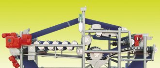
Double-bearing multi-section pumps type NDM
NDM pumps operate under conditions of high temperatures and high pressures. Used in the mining and metallurgical industries. Used when pumping oil and petroleum products, flammable and hazardous liquids with a density of no more than 1850 kg/m3, with a maximum volume concentration of solid inclusions of no more than 0.2% with a solid inclusion size of up to 0.2 mm, kinematic viscosity from 30·10 -6 m 2/s, with temperatures from -50 °C to +450 °C. The design of the pumping units fully complies with API 610 type BB5 with a flow rate of up to 700 m 3 /h
and pressure up to 2200 m. Pumps are equipped with mechanical seals, piping systems, electric motors and instrumentation depending on operating conditions and in accordance with customer requirements.
Model range of NDM pumps
Specifications: 3631-097-00217969-2014
| No. | Electric pump brand | Flow, Q (min, max), m3/h | Head, N (max, min), m | ∆h, m, add. | Rotation speed, rpm. | Engine power, Ned., kW | Unit weight, kg | Overall dimensions, LxBxH, mm |
| 1. | NDM-(E) 80-40-180/4 | 29 (17-32) | 136 | 2 | 2960 | 22 | 1500 | 2000x650x730 |
| 2. | NDM-(E) 80-40-180/5 | 29 (17-32) | 170 | 2 | 2960 | 22 | 1650 | 2000x650x730 |
| 3. | NDM-(E) 80-40-180/6 | 29 (17-32) | 204 | 2 | 2960 | 30 | 1750 | 2240x650x730 |
| 4. | NDM-(E) 80-40-180/7 | 29 (17-32) | 238 | 2 | 2960 | 37 | 1870 | 2240x650x730 |
| 5. | NDM-(E) 80-40-180/8 | 29 (17-32) | 272 | 2 | 2960 | 37 | 1920 | 2240x650x730 |
| 6. | NDM-(E) 80-40-180/9 | 29 (17-32) | 306 | 2 | 2960 | 45 | 2000 | 2500x720x730 |
| 7. | NDM-(E) 80-40-180/10 | 29 (17-32) | 340 | 2 | 2960 | 45 | 2120 | 2500x720x730 |
| 8. | NDM-(E) 80-40-180/11 | 29 (17-32) | 374 | 2 | 2960 | 55 | 2260 | 2800x780x730 |
| 9. | NDM-(E) 80-40-180/12 | 29 (17-32) | 408 | 2 | 2960 | 55 | 2610 | 2800x780x730 |
| 10. | NDM-(E) 80-40-180/13 | 29 (17-32) | 442 | 2 | 2960 | 75 | 3030 | 2800x780x730 |
| 11. | NDM-(E) 80-40-180/14 | 29 (17-32) | 476 | 2 | 2960 | 75 | 3380 | 2800x780x730 |
| 12. | NDM-(E) 80-40-180/15 | 29 (17-32) | 510 | 2 | 2960 | 75 | 3730 | 2800x780x730 |
| 13. | NDM-(E) 100-50-215/3 | 54 (32-59) | 156 | 2 | 2950 | 37 | 1650 | 2240x720x790 |
| 14. | NDM-(E) 100-50-215/4 | 54 (32-59) | 208 | 2 | 2950 | 55 | 2080 | 2240x720x790 |
| 15. | NDM-(E) 100-50-215/5 | 54 (32-59) | 260 | 2 | 2950 | 75 | 2680 | 2500x720x790 |
| 16. | NDM-(E) 100-50-215/6 | 54 (32-59) | 312 | 2 | 2950 | 75 | 3030 | 2800x780x790 |
| 17. | NDM-(E) 100-50-215/7 | 54 (32-59) | 364 | 2 | 2950 | 90 | 3410 | 2800x780x790 |
| 18. | NDM-(E) 100-50-215/8 | 54 (32-59) | 416 | 2 | 2950 | 110 | 3970 | 2800x780x790 |
| 19. | NDM-(E) 100-50-215/9 | 54 (32-59) | 468 | 2 | 2950 | 110 | 4320 | 3150x780x790 |
| 20. | NDM-(E) 100-50-215/10 | 54 (32-59) | 520 | 2 | 2950 | 132 | 4755 | 3550x1090x900 |
| 21. | NDM-(E) 100-50-215/11 | 54 (32-59) | 572 | 2 | 2950 | 132 | 5105 | 3550x1090x900 |
| 22. | NDM-(E) 100-50-215/12 | 54 (32-59) | 624 | 2 | 2950 | 160 | 5635 | 4000x1090x900 |
| 23. | NDM-(E) 150-80-240/3 | 110 (66-121) | 195 | 3 | 2950 | 90 | 1795 | 2240x780x820 |
| 24. | NDM-(E) 150-80-240/4 | 110 (66-121) | 260 | 3 | 2950 | 110 | 2145 | 2240x780x820 |
| 25. | NDM-(E) 150-80-240/5 | 110 (66-121) | 325 | 3 | 2950 | 132 | 2285 | 2500x1090x950 |
| 26. | NDM-(E) 150-80-240/6 | 110 (66-121) | 390 | 3 | 2950 | 160 | 2550 | 2800x1090x950 |
| 27. | NDM-(E) 150-80-240/7 | 110 (66-121) | 455 | 3 | 2950 | 200 | 2720 | 2800x1090x950 |
| 28. | NDM-(E) 150-80-240/8 | 110 (66-121) | 520 | 3 | 2950 | 250 | 3000 | 2800x1200x950 |
| 29. | NDM-(E) 150-80-240/9 | 110 (66-121) | 585 | 3 | 2950 | 250 | 3350 | 2800x1200x1110 |
| 30. | NDM-(E) 150-80-240/10 | 110 (66-121) | 650 | 3 | 2950 | 315 | 3860 | 3150x1200x1110 |
| 31. | NDM-(E) 150-80-240/11 | 110 (66-121) | 715 | 3 | 2950 | 315 | 4210 | 3550x1200x1110 |
| 32. | NDM-(E) 150-80-240/12 | 110 (66-121) | 780 | 3 | 2950 | 315 | 4560 | 3550x1200x1110 |
| 33. | NDM-(E) 150-100-260/3 | 205 (123-226) | 234 | 5 | 2950 | 200 | 2720 | 3750x1200x1150 |
| 34. | NDM-(E) 150-100-260/4 | 205 (123-226) | 312 | 5 | 2950 | 250 | 3000 | 3750x1200x1150 |
| 35. | NDM-(E) 150-100-260/5 | 205 (123-226) | 390 | 5 | 2950 | 315 | 3860 | 4000x1200x1210 |
| 36. | NDM-(E) 150-100-260/6 | 205 (123-226) | 468 | 5 | 2950 | 355 | 4280 | 4000x1200x1210 |
| 37. | NDM-(E) 150-100-260/7 | 205 (123-226) | 546 | 5 | 2950 | 400 | 4910 | 4250x1320x1210 |
| 38. | NDM-(E) 150-100-260/8 | 205 (123-226) | 624 | 5 | 2950 | 450 | 5260 | 4250x1320x1210 |
| 39. | NDM-(E) 150-100-260/9 | 205 (123-226) | 702 | 5 | 2950 | 630 | 6960 | 4750x1320x1250 |
| 40. | NDM-(E) 200-150-330/4 | 400 (240-440) | 500 | 10 | 2980 | 800 | 8500 | 4750x1320x1510 |
| 41. | NDM-(E) 200-150-330/5 | 400 (240-440) | 625 | 10 | 2980 | 1000 | 9400 | 4750x1460x1510 |
| 42. | NDM-(E) 200-150-330/6 | 400 (240-440) | 750 | 10 | 2980 | 1000 | 9400 | 4750x1460x1510 |
| 43. | NDM-(E) 200-150-330/7 | 400 (240-440) | 875 | 10 | 2980 | 1250 | 10000 | 5300x1800x1710 |
| 44. | NDM-(E) 200-150-330/8 | 400 (240-440) | 1000 | 10 | 2980 | 1600 | 12000 | 6000x1800x1810 |
Symbol NDM-(E) 100-50-215/3-55-A(E, I, K)
, Where:
N
- pump;
D
- two-support;
M
- multi-section;
E
- explosion-proof version;
100
— diameter of the suction pipe, mm;
50
— diameter of the pressure pipe, mm;
215
— nominal diameter of the impeller, mm;
3
- number of pump impellers;
55
- type of mechanical seal;
A
- symbol of the material of the flow part.
Characteristic fields “QH” for double-bearing multi-section pumps of the NDM type
Q-H field at rotation speed n=1470 rpm. QH field at rotation speed n=2690 rpm.
Design differences
A centrifugal pump, as is clear from its name, is a device that pumps liquid media due to the centrifugal force acting on them. The main working element of this type of pumping equipment, which ensures the formation of such force, is a wheel (or drum), on the outer cylindrical surface of which special blades are fixed.
The pump housing of this type can be made of cast iron or steel alloy. Inside such a housing there is a drive electric motor and a rotation shaft connected to it, on which the wheel with blades is fixed. According to its design, the pump impeller can be open or closed. Open impellers consist of one disk, on the outer surface of which blades are fixed, closed impellers consist of two disks connected to each other by working blades.
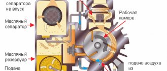
Operating principle of a centrifugal pump
The blades are located at a certain angle, their bend is directed in the direction opposite to the direction of rotation of the impeller. This arrangement of blades ensures more efficient operation of pumping equipment. The suction of the pumped liquid medium into the internal chamber of the pump, as well as its expulsion into the pressure line, is carried out through the nozzles.
The principle by which both single-stage devices and multi-stage pumps operate is as follows.
- The liquid, located in the inner part of the pump before it starts, is captured by the blades when the impeller rotates and begins to move with them.
- Under the influence of centrifugal force, the liquid is thrown towards the walls of the inner chamber, due to which high pressure is created near them.
- As it moves through the discharge port area, the high-pressure liquid is pushed into it.
- When the liquid pumped by the pump is thrown towards the walls of the working chamber, a vacuum of air is created in the central part of the latter, which facilitates the suction of the liquid medium through the inlet pipe.
» data-lazy-type=»iframe» src=»data:image/gif;base64,R0lGODlhAQABAIAAAAAAAP///yH5BAEAAAAALAAAAAABAAEAAAIBRAA7″>
Due to the above-described principle of operation in pumps of both single-stage and multi-stage types, the continuity of the process of suction and expulsion of the pumped liquid is ensured when the impeller rotates. The scope of application of this type of pumping equipment is significantly expanded by the fact that, unlike piston devices, it does not create pulsations of liquid pressure in the pipeline system it serves.
As mentioned above, single-stage and multi-stage centrifugal pumps have design features that determine the differences in their technical characteristics. Thus, the main design elements of a single-stage pump are:
- the body, which is often called the “snail”;
- impeller with blades;
- shaft sealing elements;
- a shaft connected to the drive motor and providing rotation of the impeller;
- chamber sealing elements with oil bath;
- support for bearing assembly;
- load-bearing support;
- hole through which the oil level in the chamber is controlled.
Diagram of a single-stage monoblock pump
A single-stage centrifugal pump, unlike multi-stage models, is equipped with one impeller. A centrifugal multistage pump can be equipped with two or more impellers with blades, which can significantly increase the efficiency of such equipment.
Due to the presence of several impellers, centrifugal multistage devices, when compared with single-stage ones, have certain advantages.
- Using multistage pumps, it is possible to pump liquid with a higher productivity, which characterizes the amount of liquid medium that the hydraulic machine passes through itself per unit of time.
- Multistage pumps are capable of generating a fluid flow with higher pressure levels, measured in meters of water column. In fact, the liquid pressure created by multistage electric pumps is the sum of the pressures created by each of its stages. This quality of multi-stage hydraulic machines makes it possible to achieve higher fluid pressure in the pipeline systems they serve and move it through them over longer distances and greater heights.
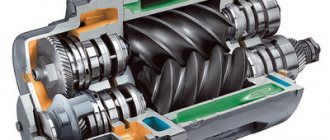
Diagram of a multistage sectional pump
A multistage centrifugal pump, depending on its design, can be sectional or spiral. In sectional type devices, during the pumping process, the liquid medium moves sequentially from the first section of the pump to the last, while the liquid pressure also increases sequentially. Modern models of multistage sectional pumps are capable of providing liquid pumping performance up to 900 m3
3
, while the pressure of the working environment created by such devices can reach up to 1900 meters of water column.
Multi-section horizontal pumps TsNS, TsNSG
TsNS-13, TsNS-38, TsNS-60 - horizontal, centrifugal, multi-stage, sectional electric pump units. Purpose of central nervous system pumps
Horizontal centrifugal multi-stage multi-section pumps TsNS 13-70... 350, TsNS 38-44... 220, TsNS 60-66... 330 are designed for pumping water with a pH value of 7-8.5, with a mass fraction of mechanical impurities of no more than 0.1% and solid particle size not exceeding 0.1 mm and temperature from 1 to 45°C.
The TsNSG pump is designed for pumping hot water with temperatures up to 105°C
TsNSG pumps are available with flow rates from 13 to 300 m3/hour and pressures:
- Pump TsNSG 13-70…350,
- Pump TsNSG 38-44…220,
- Pump TsNSG 60-66…330,
- Pump TsNSG105-98…490,
- Pump TsNSG180-85…425,
- Pump TsNSG300-120…600
Technical characteristics of TsNSG pumps
The efficiency factor is not less than 0.67 for pumps TsNSG 38-44...38-220, TsNSG 13-70... 13-350.
The pressure characteristics of TsNSG 38-44...220 pumps correspond to the characteristics of TsNS 38-44...220 (when tested on water). Working part of the characteristics for the supply of pumps TsNSG 38-, TsNS38- (28-48 cubic meters/hour)
The pressure characteristics of TsNSG 60-66...330 pumps correspond to the characteristics of TsNS 60-66...330 (when tested on water). Working part of the characteristics for the supply of pumps TsNSG 60-, TsNS60- (48-80 cubic meters/hour)
The pressure characteristics of TsNSG 13-70...350 pumps correspond to the characteristics of TsNSG 13-70...350 pumps (when tested on water). Working part of the characteristics for the supply of pumps TsNSG 13-, TsNS13- (10-17 cubic meters/hour)
The permissible vacuum suction height of the TsNSG pump, with sufficient accuracy for practice, is determined by the dependence Nperm/vac = 10-hperm, m
where 10 is barometric pressure
hadd,m is the permissible cavitation reserve of the TsNSG pump.
You can find out more detailed technical characteristics of TsNSG pumps by clicking on the link.
Design and materials of TsNSG pumps
In multistage central nervous system pumps, the flow of pumped liquid is moved sequentially by several impellers mounted on the same shaft in one housing.
Conditions for normal operation of TsNSG pumps
CNS type pumps operate stably and for a long time with a headwater of 2-6 m. In the absence of headwater, cavitation quickly destroys these high-speed pumps. When installing them to pump water with a temperature of more than 45° C, it is necessary to increase the pressure.
TsNSG type pumps must operate with a head pressure of up to 10 m. The bearing housings of this modification have cooling chambers.
Symbol:
Pumps TsNSG 38-132
- CNS - centrifugal sectional;
- 38 — flow rate (m3/hour);
- 132—pressure (m);
- G - for hot water with temperatures from +45° to +105°C.
Pumps CNS 38-154
- CNS - centrifugal sectional;
- 38 — flow rate (m3/hour);
- 154—pressure (m);
- for cold water with temperatures from +1 to +45°C.
Operating principle of TsNSG pumps
Rotating, the impeller of the central heating pump imparts a circular motion to the liquid located between the blades. Due to the resulting centrifugal force, the liquid from the center of the pump wheel moves to the external outlet, and the vacated space is again filled with liquid coming from the suction pipe of the central nervous system or central heating pump under the influence of atmospheric or excess pressure. Having left the impeller, the liquid enters the channels of the pump guide vane and then into the second impeller with the pressure created in the first section. From there, the liquid enters the third impeller with increased pressure created by the second section, etc. Coming out of the last impeller of the TsNSG pump, the liquid passes through the outlet guide vane into the discharge cover and enters the discharge pipeline.
You can order a central nervous system or central nervous system pump using a multi-line phone. You can also send your application by email
CNS and CNSG pumps are always available in stock.
You can find out more detailed information about TsNSG pumps from the technical description of the pumps by clicking on the link.
Operating principle
The housing of such a pump usually has a snail-shaped shape. Inside there is a shaft on which an impeller with blades is located. There are two flanges at the edges - suction and pressure. In most cases, the pump unit consists of a hydraulic pump and an electric motor.
Next, we will consider each element separately and describe the functions that they perform:
- Electric motor - this element in the design of a centrifugal pump plays the role of a drive. The driving part of the electric motor, which is located in the pump, is carefully sealed.
- Impeller shaft - its function is to transmit rotational action from the electric motor to the impeller.
- The impeller is located on a shaft and has curved blades.
- Sealing parts – protect parts of the unit from ingress of the pumped liquid.
Basic principles of operation of a centrifugal pump:
- Through the suction flange, the liquid enters the working chamber of the pump and moves due to the blades located on the impeller.
- With the help of centrifugal force, the liquid medium hits the walls of the working chamber and creates excess pressure.
- The excess pressure forces the fluid through the pressure flange.
- The absorption of a new portion of liquid occurs as a result of the formation of excess pressure in the working chamber.
Centrifugal pumps are manufactured as single-stage or multi-stage. The latter are called “sectional centrifugal pumps”. In such units, an increase in the total pressure drop is achieved, which is proportional to the number of sections of the unit. At the same time, the principle of their operation in any design remains the same - the liquid moves under the influence of centrifugal force, which is created by a rotating impeller.
In accordance with the processes listed above,
all elements of the centrifugal pump ensure continuous pumping of liquid and guarantee the stability of all necessary pump operating parameters.
This principle of pump operation applies not only to the surface type, but also to the deep type.
The centrifugal pump must not be operated if there is no liquid inside the working chamber. If these rules are neglected, the unit will fail. It is advisable to use a pump for pumping large volumes of liquid on an ongoing basis at low pressures.
The most important thing in the operation of the unit is not to encounter such a problem as cavitation. This process occurs as a result of the formation of bubbles in the liquid due to the occurrence of rarefaction zones in it. They end up in a zone with higher pressure. The bubbles collapse and create powerful energy that destroys the insides of the pump. But there are cases when the housing itself is destroyed.
Important! The first sign of cavitation is the noisy operation of the pump.
More details about the operation of a centrifugal pump are described in the following video:
What does this give?
Anyone who is familiar with the operation of compressor units will understand immediately.
In fact, the operating principle of multistage pumps is practically no different. The pumped liquid moves sequentially through sections, in each of which its pressure increases. The water pressure at the outlet of the device is determined by the total value created at each stage. This technical solution gives certain advantages to multistage pumps over traditional analogues.
- One device, without additional elements included in the system, creates increased pressure in the pipe (up to 400 m). If we take into account that most private buildings have a complex water supply scheme, with several “points” for dispensing liquid and a significant distance from the source (well, borehole) from the house, this is a more than significant plus.
- Relative noiselessness. There is no need to talk about the complete absence of sounds from a running engine, but their level is so insignificant that this is not taken into account. This can be explained simply - to create the required pressure, it makes no sense to use a large motor in the pump. In multi-stage models, the pressure increases due to the synchronous operation of several wheels. Consequently, they are characterized by an excellent combination of indicators such as power and generated pressure. This is already the third plus of devices in this group.
Do multistage pumps have any disadvantages?
From the point of view of practical application, there is only one - they are suitable only for working with clean liquids. It is understood that only the smallest fractions (contamination up to 100 g/m3) are allowed to be present in water, otherwise the efficiency of the device will sharply drop and the service life will be reduced. Many people put multi-stage pumps at a disadvantage because of their high price. Yes, they cost about 2.5 times more than traditional analogues. But an analysis of all aspects of their practical use shows that installing this particular device is sometimes more expedient. The fact is that to create the same pressure, if you purchase a model with one impeller, you will need a product with more power. And this characteristic directly affects its price. In addition, increased energy consumption cannot be discounted. Therefore, the savings are practically zero, and in terms of ease of installation (due to compactness), multistage pumps are preferable. And they are cheaper to operate.
How are devices in this group classified? They differ in the spatial orientation of the shaft on which the impellers are located. Vertical pumps are submersible models, while horizontal pumps are mainly surface pumps. To provide private buildings with water from an autonomous source, devices of the latest variety are mainly purchased. The fact is that they are more versatile and can be used for other purposes. For example, to increase pressure on the highway. You can get acquainted with one of the representatives of models of this type - MH 500C - its characteristics and cost by clicking on the link.
Types of pumps
There are a large number of pumps on the modern market for pumping liquids, and the most popular of them are centrifugal pumps. These pumps have differences in their characteristics and they are single-stage and multi-stage.
Multistage pump
Principle of operation
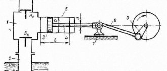
A multistage pump is assembled from a pressure pipe, a wheel, a guide vane and a spiral outlet.
When the wheel rotates, the part that has individual bends on the blades is filled with water. The water then enters the channel, which has a spiral outlet. Due to this structure, it is possible to increase the pressure.
There are a very large number of pump models, but they will have differences in the assembly design. For example, how the shaft will be located, the shape of the nozzles and the number of installed impellers. Before choosing a pump, you need to consider its dimensions and power.
Design and principle of operation of a multistage pump
A single stage pump is a unit that has one impeller, while a multistage pump has two or more impellers. The operating principle of a multi-stage unit is similar to the operating principle of a single-stage unit, and performance directly depends on the number of wheels. Therefore, multistage pumps pump more water over a period of time and have increased pressure. This means that using multi-stage pumps, liquid can be pumped over long distances.
Types of Centrifugal Water Pumps
Multistage centrifugal pumps come in a variety of designs:
Sectional;- Spiral.
A sectional multistage pump pumps water gradually, that is, from drum to drum. The maximum performance level of the equipment is nine hundred cubic meters of liquid per hour with a pressure of one thousand nine hundred meters.
Positive and negative qualities
- Over a wide range of flows, high efficiency and pressure values will be maintained, as a result of flat qualities.
- High rotation speeds facilitate the use of electric motors and electric drives, as well as turbines, for pumps;
- The power changes smoothly, this allows the pump to start even when the outlet valve is closed or the check valve is closed.
- They have good stability when operating devices and expanding technical quantities, as well as when connecting pumps in parallel and in stages, when performing work on one pipeline.
- Transient processes occur quite smoothly; this occurs when the operating modes of water systems change.
- Pumps are always placed above the water level in the container for consumption.
Due to various factors, pump performance changes.
These factors are:
- The diameter of the impellers is ground;
- The rotation speed varies;
- The frequency of the power supply varies;
- The pump is quite inexpensive because inexpensive materials are used in its production. For example:
- Steel;
- Cast iron;
- Polymer materials;
- This pump is easy to maintain and operate.
- Reliable during operation.
- The liquid supply is large.
- The water flow is supplied with slight uniform pulsations.
- Also works well even in contaminated liquids.
- The negative qualities of centrifugal multistage pumps are:
- It is necessary to fill the device before starting it;
- Prone to cavitation;
- If the pump pumps viscous liquids, the efficiency level decreases.
- If the liquid supply is small, then the efficiency level becomes very low.
- Multistage centrifugal pumps are best used for large water supplies and at medium, low pressures.
How do centrifugal pumps work?
The centrifugal multistage pump is an equipment that immediately attracts attention. Depending on the conditions of use, different devices are produced in this group. Features of use largely determine the design development.
Note. For example, some models work with fecal waste and chemically active liquids, water and heating.
How the unit works:
- The work of the wheels, or rather, the force with which they work, becomes in this case the basis of action for the entire mechanism.
- When they rotate, pressure is created inside the system, liquid is pumped from one place to another.
In the body of the device, a certain amount of pressure is applied to the water when the liquid gets inside. At first the pressure is high-speed, but then it becomes piezometric. This happens after the wheel stage has been completed.
Areas of application
Use of central heating in production.
The scope of application of centrifugal pumps is extremely wide. They are used in thermal power plants to power boilers, supply water to the regenerative heat exchange system, and feed network heating plants. NPPs use sealed centrifugal units. At thermal power plants they are used in hydraulic ash removal systems.
CNs are widely used in industrial enterprises, agriculture and urban water supply systems. They are used to supply reagents and solutions in production flow charts. They are used in construction and the coal industry for hydromechanization of soil development and the hydraulic method of coal mining.
In agriculture, deep water pumps are used to supply water to livestock farms. High-capacity pumping units are installed in field irrigation systems.
This is interesting: How to get a pump out of a well: pulling out a stuck or fallen pump
Design of centrifugal pumps CNS
The impellers are mounted on one common shaft and are located in a single housing, divided into sections. The total pressure of such a centrifugal pump is equal to the sum of the pressures created by each impeller. Centrifugal horizontal multistage pumps of the CNS type are used for pumping clean water with temperatures up to 60 ºC. Pumps of this type can be normal or high-speed. The seal between the individual sections is carried out using special gaskets.
Since the casing design is sectional, the number of sections, and therefore the impellers, can be increased or decreased. Multistage centrifugal pumps CNS are produced with the number of sections (impellers) from 2 to 10. Some pump designs are manufactured with two impellers of left and right rotation. CNS type pumps are most often used in the mining industry for pumping water from mines and mining workings.
Since it is easy to create high water pressure with the help of multi-stage pumps, they are used in fire extinguishing systems and for supplying water to high-rise civil and industrial structures. The advantages of multistage pumps include the ability to increase or decrease water pressure by changing the number of sections. The disadvantages of such pumps are the complexity of the design, which makes it difficult to assemble and disassemble the pump, as well as a large number of high-precision parts, which complicates repair work.
Pumps can have different configurations by design. The most widespread are horizontal centrifugal pumps, which can be either single-stage or 2 or more stages. These pumps include CNS pumps – multi-stage sectional centrifugal pumps. In these pumps, liquid is moved using several impellers, which are mounted on a common shaft, in one housing, divided into sections. The pressure of the pumped liquid is equal to the sum of the pressures of all impellers.
Pumps of this type are designed for pumping clean water with a temperature of no more than 1050 C and a solid particle size of no more than 0.1 mm with a total share of mechanical impurities of no more than 0.1% of the total mass of the pumped liquid.
Preparing for work
Preparing the pump for operation.
Some types of centrifugal pumps do not require preparation before starting. These include deep (borehole) pumps, heating system pumps and other units, the housings of which are constantly filled with water. Household hydraulic units designed to lift water from a well or supply it from a reservoir for irrigation require some preparation before turning on.
When starting a central pump with a dry hydraulic part, a vacuum is not created in the suction pipe, and liquid does not flow to the impeller. As a result of such work, the rotating parts heat up, which leads to pump failure. There are several options to solve this problem.
Filling water from a pipeline
Used for water supply systems with permanently fixed pipelines. Most often, this method is used to lift water from a well. The pump is installed in such a way that the distance to water is no greater than the value specified in the description (passport) of the device. A check valve is installed on the suction pipeline to prevent water from draining. The pump housing along with the pipeline is filled with water, and then the engine is turned on.
This procedure is carried out at the first start. If the check valve works correctly, the water will not drain and subsequent starts will take place with the circuit filled. If the pump is rarely started, then the pump piping is made in such a way that it is possible to supply water from the pressure pipeline to the pump suction, i.e., the unit is bypassed. Water is supplied until all the air is removed from the filled circuit.
Filling water from the tank
Centrifugal pump in action.
To fill the hydraulic part, containers with water are used. They are located above the unit, then the liquid will flow by gravity into the pump and pipeline. After starting the central heating unit, close the valve on the filling line. To supply water to the tank, a tube with shut-off valves is installed on the pressure pipeline of the pump. This process can be automated by placing a float valve in the container, which will close when the tank is completely filled.
In some cases, storage tanks are used, which are installed at the pump suction. Water is supplied to the central pump from the bottom point of the tank, and the suction pipeline is connected at the top. The battery must not have connections with the atmosphere other than those provided for by the design. The tank capacity is chosen equal to twice the volume of the cavities of the pump and suction pipeline. With a completely sealed system, after stopping the pump, the level in the battery will allow subsequent switching on without filling the container with liquid.
Basic malfunctions of multistage pumps
Centrifugal multistage units are considered one of the most reliable, but they also fail over time. This may be due not only to the gradual wear of the working parts of the equipment, but also to its improper operation.
If a household or industrial unit does not pump water, first of all you need to check its wheel blades, suction pipe and filter element mesh. If one or all of these elements become clogged, the performance of the equipment will begin to gradually decline. The main signs of clogging are considered to be a sharply decreased pressure and atypical pumping of liquid - it will not flow, but pulsate.
Many owners of multi-stage equipment are faced with engine overload. To prevent this, the outlet pipe will need to be equipped with a valve - a special limiter for adjusting the volume of pumped out liquid.
Another common problem is the accumulation of air in the working chamber of the device. This occurs due to improper starting of the unit. To solve it, you need to release the air and turn on the equipment again. You need to start at low speeds, gradually moving to high shaft speeds.
Sometimes a multi-stage unit stops working due to water accumulated in its housing. It should only go inside the working chamber. If it has leaked into other places, then the seals need to be replaced. In addition, you will need to inspect the shaft and, if necessary, replace its lubricant.
Main manufacturers
The major players in the centrifugal pump market can also be broken down by the industries in which they are strongest:
Water supply, drainage, water treatment
- Grundfos: grundfos.com
- Wilo:wilo.ru
- Xylem Group of Companies. Pumps Lowara, Goulds, Flygt, Vogel, etc.: https://xylem.ru
- KSB: https://www.ksb.com/ksb-ru/
- Pentair: www.pentair.com
- Ebara: https://www.ebaraeurope.ru/
- Caprari: www.caprari.it
Petrochemical industry
- Flowserve www.flowserve.com
- ITT www.itt.com/
- Sulzer www.sulzer.com
- Hermetic Pumpen www.hermetic-pumpen.com
- Kirloskar pumps www.kirloskarpumps.com/
- Ruhrpumpen www.ruhrpumpen.com
Chemical industry
- Munsch munsch.de/
- Pompe Travaini www.pompetravaini.it/
- Someflu pump www.someflu.com/
- Rutschi Gruppe www.grupperutschi.com
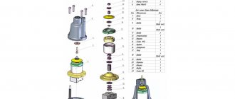
Design features of a centrifugal pump
If you look at the equipment in cross-section, you can identify the main structural elements:
An electric motor that acts as a drive.
A shaft that transmits rotation from the engine to the operating pulley.
A pulley with blades that move liquid inside the working chamber.
Bearing unit ensuring easy rotation of the shaft and wheel.
Seals that protect the structure from the negative effects of liquid media.
The snail-shaped body is equipped with two pipes.
Centrifugal multistage sectional pumps type TsNSg
Centrifugal multistage sectional pumps of the TsNSg type and electric pumping units based on them are designed for pumping water with a pH value of 7...8.5 with a temperature of no more than 378 K (105°C), with a mass fraction of mechanical impurities of no more than 0.1% , the size of solid particles is not more than 0.1 mm. microhardness no more than 1.47 GPa (14700 kgf/cm2). They are used in the heat and power industry to supply feed water to steam boilers of low-power thermal power plants and in heating and hot water supply systems. Pumps (units) are not intended for operation in explosive and fire hazardous areas.
DESIGN The unit consists of a pump and a drive motor mounted on a common foundation frame and connected to each other using an elastic bush-pin coupling. The TsNSg pump is a centrifugal multistage sectional, horizontal with one-sided arrangement of unloaded impellers. The pump consists of a suction and discharge casing with sections installed between them. The diaphragm sections with guide devices inserted into them are connected to each other and to the suction and discharge casings using tie rods. The joints of the sections are sealed with rubber rings. The pressure pipe is directed vertically upward. The suction pipe is located horizontally and directed to the right of the vertical axis of the pump when viewed from the drive side. The connecting dimensions of the flanges of the suction and discharge pipes are made in accordance with GOST 12815-80, version 1. The shaft seal is stuffing box.
Application:
- industrial enterprises – for water and heat supply in production processes
- public utilities – for water and heat supply
- thermal power plants – power supply to low and medium power boilers
- thermal power plants – for pumping condensate
CNS(G) 13-ХХХ
| Pump type | Nominal flow, m3/h | Head, m | Number of pump stages | power, kWt | Rotation speed, rpm | Additional cav. reserve, m, no more | Pump weight, kg | Unit weight, kg |
| CNS (TSNSG) 13-70 | 13 | 70 | 2 | 11 | 3000 | 3 | 195 | 340-360 |
| CNS (TSNSG) 13-105 | 13 | 105 | 3 | 11 | 3000 | 3 | 225 | 370-390 |
| CNS (TSNSG) 13-140 | 13 | 140 | 4 | 15 | 3000 | 3 | 255 | 460-480 |
| CNS (TSNSG) 13-175 | 13 | 175 | 5 | 18.5 | 3000 | 3 | 280 | 500-530 |
| CNS (TSNSG) 13-210 | 13 | 210 | 6 | 18.5 | 3000 | 3 | 310 | 540-570 |
| CNS (TSNSG) 13-245 | 13 | 245 | 7 | 22 | 3000 | 3 | 340 | 580-620 |
| CNS (TSNSG) 13-280 | 13 | 280 | 8 | 30 | 3000 | 3 | 370 | 630-670 |
| CNS (TSNSG) 13-315 | 13 | 315 | 9 | 30 | 3000 | 3 | 390 | 660-700 |
| CNS (TSNSG) 13-350 | 13 | 350 | 10 | 30 | 3000 | 3 | 425 | 690-730 |
CNS(G) 38-ХХХ
| Pump type | Nominal flow, m3/h | Head, m | Number of pump stages | power, kWt | Rotation speed, rpm | Additional cav. reserve, m, no more | Pump weight, kg | Unit weight, kg |
| CNS (TSNSG) 38-44 | 38 | 44 | 2 | 11 | 3000 | 3.6 | 191 | 330-345 |
| CNS (TSNSG) 38-66 | 38 | 66 | 3 | 15 | 3000 | 3.6 | 219 | 395-420 |
| CNS (TSNSG) 38-88 | 38 | 88 | 4 | 18.5 | 3000 | 3.6 | 247 | 440-485 |
| CNS (TSNSG) 38-110 | 38 | 110 | 5 | 22 | 3000 | 3.6 | 275 | 500-580 |
| CNS (TSNSG) 38-132 | 38 | 132 | 6 | 30 | 3000 | 3.6 | 303 | 550-620 |
| CNS (TSNSG) 38-154 | 38 | 154 | 7 | 30 | 3000 | 3.6 | 331 | 580-645 |
| CNS (TSNSG) 38-176 | 38 | 176 | 8 | 30 | 3000 | 3.6 | 359 | 610-685 |
| CNS (TSNSG) 38-198 | 38 | 198 | 9 | 37 | 3000 | 3.6 | 387 | 695-750 |
| CNS (TSNSG) 38-220 | 38 | 220 | 10 | 45 | 3000 | 3.6 | 415 | 745-800 |
CNS(G) 60-ХХХ
| Pump type | Nominal flow, m3/h | Head, m | Number of pump stages | power, kWt | Rotation speed, rpm | Additional cav. reserve, m, no more | Pump weight, kg | Unit weight, kg |
| CNS (TSNSG) 60-66 | 60 | 66 | 2 | 22 | 3000 | 4.5 | 226 | 450-490 |
| CNS (TSNSG) 60-99 | 60 | 99 | 3 | 30 | 3000 | 4.5 | 263 | 490-530 |
| CNS (TSNSG) 60-132 | 60 | 132 | 4 | 45 | 3000 | 4.5 | 309 | 590-640 |
| CNS (TSNSG) 60-165 | 60 | 165 | 5 | 55 | 3000 | 4.5 | 345 | 705-780 |
| CNS (TSNSG) 60-198 | 60 | 198 | 6 | 55 | 3000 | 4.5 | 381 | 730-805 |
| CNS (TSNSG) 60-231 | 60 | 231 | 7 | 75 | 3000 | 4.5 | 420 | 910-1080 |
| CNS (TSNSG) 60-264 | 60 | 264 | 8 | 75 | 3000 | 4.5 | 462 | 935-1100 |
| CNS (TSNSG) 60-297 | 60 | 297 | 9 | 75 | 3000 | 4.5 | 499 | 960-1130 |
| CNS (TSNSG) 60-330 | 60 | 330 | 10 | 110 110 | 3000 | 4.5 | 546 | 1300-1440 |
| CNS (CNSG) 60-50 | 60 | 50 | 2 | 18.5 | 1500 | 3 | 460 | 780-820 |
| CNS (TSNSG) 60-75 | 60 | 75 | 3 | 22 | 1500 | 3 | 520 | 870-910 |
| CNS (TSNSG) 60-100 | 60 | 100 | 4 | 30 | 1500 | 3 | 575 | 960-1015 |
| CNS (TSNSG) 60-125 | 60 | 125 | 5 | 45 | 1500 | 3 | 635 | 1095-1140 |
| CNS (TSNSG) 60-150 | 60 | 150 | 6 | 55 | 1500 | 3 | 690 | 1230-1310 |
| CNS (TSNSG) 60-175 | 60 | 175 | 7 | 55 | 1500 | 3 | 750 | 1300-1380 |
| CNS (TSNSG) 60-200 | 60 | 200 | 8 | 75 | 1500 | 3 | 810 | 1520-1690 |
| CNS (TSNSG) 60-225 | 60 | 225 | 9 | 75 | 1500 | 3 | 865 | 1580-1750 |
| CNS (TSNSG) 60-250 | 60 | 250 | 10 | 75 | 1500 | 3 | 925 | 1650-1820 |
CNS(G) 105-ХХХ
| Pump type | Nominal flow, m3/h | Head, m | Number of pump stages | power, kWt | Rotation speed, rpm | Additional cav. reserve, m, no more | Pump weight, kg | Unit weight, kg |
| CNS (TSNSG) 105-98 | 105 | 98 | 2 | 55 | 3000 | 5,5* | 480 | 960-1080 |
| CNS (TSNSG) 105-147 | 105 | 147 | 3 | 75 | 3000 | 5,5* | 518 | 1140-1310 |
| CNS (TSNSG) 105-196 | 105 | 196 | 4 | 110 | 3000 | 5,5* | 576 | 1470-1610 |
| CNS (TSNSG) 105-245 | 105 | 245 | 5 | 132 | 3000 | 5,5* | 634 | 1580-1830 |
| CNS (TSNSG) 105-294 | 105 | 294 | 6 | 160 | 3000 | 5,5* | 715 | 1600-1970 |
| CNS (TSNSG) 105-343 | 105 | 343 | 7 | 160 | 3000 | 5,5* | 775 | 1660-2030 |
| CNS (TSNSG) 105-392 | 105 | 392 | 8 | 200 | 3000 | 5,5* | 836 | 1810-2160 |
| CNS (TSNSG) 105-441 | 105 | 441 | 9 | 250 | 3000 | 5,5* | 897 | 1930-2510 |
| CNS (TSNSG) 105-490 | 105 | 490 | 10 | 250 | 3000 | 5,5* | 958 | 2000-2580 |
Characteristics of horizontal multistage CNS pumps
Multistage horizontal centrifugal pump TsNS 60-330 is designed for pumping cold water having a temperature of no higher than 400 C, with permissible sizes of mechanical impurities no more than 0.2 mm. These pumps are used in water supply systems of civil and industrial facilities, to increase pressure in cold water lines, as well as to pump water into oil-bearing horizons. The pump consists of a housing and a rotor. The pump rotor is a shaft on which the impellers are mounted. The wheel housing consists of separate sections, which allows you to change the pressure by installing the required number of impellers.
CNS 60-330:
- CNS – sectional centrifugal pump
- Water supply – 60 m3/hour
- Pressure – 330 m.w.st.
- Power – 90 kW
- Speed – 3000 rpm
Pump CNS 13-350 is a sectional centrifugal pump designed for pumping water and similar non-explosive and fire-hazardous liquids containing solid mechanical impurities of no more than 0.1% of the total volume and with dimensions no more than 0.2 mm.
- Supply – 13 m3/hour
- Head 350 m.w.st.
- Electric motor power – 30 kW
- Speed – 2950 rpm.