Information about the manufacturers of the Universal-2 lathe
The Universal-2 multifunctional lathe was developed by the ENIMS organization (Experimental Research Institute of Metal-Cutting Machine Tools) in 1975.
The manufacturer of the Universal-2 table lathe is the Moscow Machine Tool Plant StankoKonstruktsiya , founded in 1932.
The Universal-2 table lathe was also produced by the Vladimir Precision Equipment Plant in Vladimir, founded in 1935. Currently, the Vladimir Machine Tool Plant VSZ Tekhnika, LLC .
Description and purpose
The Universal-2 desktop multifunctional lathe is produced by the Moscow Machine Tool Manufacturing Plant (in the past it was also produced by the Vladimir Precision Equipment Plant). The basis for the design in the seventies was the Station wagon and the most promising equipment at that time, and the result exceeded expectations. Even now it does not lose its relevance without significant upgrades.
This is an excellent option for a home or repair workshop, as well as for auxiliary production. His strengths:
- Compactness. The largest dimension - length - is less than seventy centimeters, and the weight is less than forty kilograms. This allows you to place the Universal-2 in the most cramped conditions.
- Versatility. It is determined by the given functionality and the center-to-center distance of 180 mm. In practice, this turns out to be quite a lot, and it fits into a huge range of products.
- Ability to work with both steel and alloys of other metals, as well as wood and plastic.
- Ease of Management. If you do not need to produce particularly complex or important products, then general work skills are sufficient.
- Excellent accuracy. It is at the average level for the entire class of screw-cutting equipment.
For processing, workpieces are mounted in a standard chuck or in centers. There is also a hole in the spindle for bar material.
Allowed turning operations:
- External groove and internal sprout. The design allows you to work not only with cylindrical, but also with conical and even shaped surfaces. In many ways, the complexity of the work is determined by the qualifications of the performer.
- Chamfering and trimming ends.
- Drilling holes. This is an auxiliary function that allows you to drill holes without changing the existing base and without wasting extra time.
- Segment.
- Metric thread cutting. For this, a cutter is used, which makes the whole process more productive and accurate.
- For work, an inexpensive GOST tool is used, but if necessary, you can look for more productive and durable replacement plates.
The listed operations determine a significant part of the processing used in mechanical engineering. They require specialized tools and adherence to regimens.
IMPORTANT: Improper operation can cause damage to both the equipment and the workpiece.
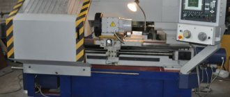
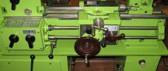
General view of the Universal-2 lathe
Photo of the Universal-2 lathe
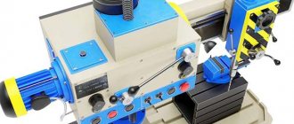
Drive and guitar of the Universal-2 lathe
Drive of the Universal-2 lathe
Grinding version of the desktop machine Universal-2
Milling version of the desktop machine Universal-2
Version for working with a jigsaw on a desktop machine Universal-2
Version for working with a circular saw on a table saw Universal-2
Planing version of the desktop machine Universal-2
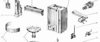
Set of accessories for the desktop machine Universal-2
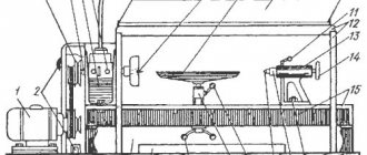
Location of the components of the Universal-2 lathe
Location of the components of the Universal-2 lathe
Location of the components of the Universal-2 lathe
Location of the components of the Universal-2 lathe
Machine Features
With the help of Master-Universal 2.2 you can perform various planing and sawing work. So, for example, using the machine as a planer, you can perform jointing along a face or edge; if necessary, a clamping device can be used to perform this operation. Planing can also be done at a given angle. Also, with the help of Master-Universal 2.2, carpentry work such as thicknessing is available.
Using Master-Universal 2.2 as a sawing machine, you can perform an operation both along and across the fibers; moreover, the operator can adjust the depth of the required cut or its angle. Also, using the machine, you can perform milling or drilling operations of varying complexity, but the most important thing is that the transition from one operation to another does not take much time and is carried out in just a few steps.
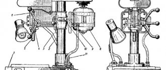
Design and main parts of the Universal-2 multifunctional lathe
The “Universal-2” machine, when reconfiguring and installing additional devices, can have the following basic designs:
- turning version
- drilling, milling and grinding
- for working with a circular saw on wood
- for working with a jigsaw on wood
- jointer
- sharpening
In the listed versions, the machine includes the following main parts and devices:
- bed that carries all parts of the machine
- round longitudinal guides screwed to the frame
- removable spindle head mounted on the machine or machine stand; serves to secure and drive the workpiece or cutting tool into rotation and, if necessary, can be rotated 360°
- electric motor for driving the main movement, mounted on sleeve 9 using a terminal clamp. The electric motor, step-pulley belt drive and sleeve with spindle are a single unit that can be completely removed from the machine;
- cross support, consisting of a carriage moving along round longitudinal guides, and a transverse slide moving along round guides in a direction perpendicular to the longitudinal guides. The support serves to secure the cutting tool or workpiece and impart feed movement to it. The carriage is moved by rotating the longitudinal lead screw either manually using a handwheel located on the right, or mechanically from the spindle through a set of interchangeable gear wheels 7; cross slide - by rotating the cross lead screw using the handwheel located at the front
- tailstock, fixed in the required position on round longitudinal guides using a clamp. The quill is moved in the headstock body by a handwheel. The headstock serves mainly to support the workpiece with a center installed in the quill, as well as to secure tools intended for processing holes with drills, reamers, etc.);
- a guitar of replaceable gears for adjusting the drive chain of the caliper feed to the required values of the longitudinal feed when turning or for the pitch when cutting threads. The guitar consists of four (when configured for pitch) or three (when configured for pitch) replaceable gears and a ramp with a terminal clamp for securing it to a bracket with a radial groove for installing the axis of replaceable gears
- step-pulley belt drive for stepwise regulation of the spindle speed and for transmitting power and torque from the electric motor to the spindle
- a sleeve with a spindle rotating in it on rolling bearings; devices for securing the workpiece or cutting tool are installed on the right end of the spindle, and a sharpening device is installed on the left end; the sleeve can move along its axis in the spindle head and be secured with two screws;
- electrical switch to enable forward spindle rotation, stop and reverse spindle rotation
- longitudinal lead screw
- stand mounted on the bed for drilling, milling and grinding work with a vertical, inclined and horizontal spindle position
- bracket with which the spindle head is attached to the stand
- handle for moving the sleeve along its axis
- drill chuck
- drill bit held in a drill chuck or collet chuck
- a vice installed on the transverse slide of the caliper and used to secure the workpiece. Instead of a vice, you can also install a rectangular table with T-shaped slots, on which the part is secured during processing using clamps;
- collet clamp for securing cutters, drills and other tools, as well as small workpieces during turning (for centering, drilling and other operations, installation of a collet clamp on the tailstock quill is provided);
- cutter clamped in a collet clamp
- a rectangular table mounted on the transverse slide of the support, on which the part is secured during processing using clamps
- mandrel for securing the grinding wheel, screwed onto the spindle
- grinding wheel
- table mounted with a bracket on the sleeve for sawing with a circular saw
- circular saw for wood
- jigsaw table
- bracket for mounting the table on the sleeve
- jigsaw
- an eccentric device mounted on the front end of the spindle to impart vertical reciprocating motion to the saw
- table for planing the planes of slats, bars and boards, fixed with a bracket on the sleeve
- double blade drum
- an abrasive wheel for sharpening a cutting tool, installed using a mandrel at the rear end of the machine spindle. To protect the machine mechanisms from abrasive dust during sharpening, they are covered with a napkin.
- machine starting electrical equipment unit
Standard delivery set
When purchased, certain accessories and tools are included as standard. In some cases there may be additional components.
Accessories
The basic set includes the following accessories for the Universal series machine:
- three-jaw chuck complete with flange and ring;
- several return jaws and a key to the chuck;
- shank for a type of drill chuck;
- 2 thrust centers and one rotating;
- mandrel assembly for boring;
- collet F6 and F8;
- surface grinding device;
- milling and drilling device;
- vice;
- sharpening;
- mechanism for processing wooden structures;
- handyman;
- jigsaw;
- mechanism for working with a circular saw;
- screen;
- polyethylene oil can;
- cartridge casing.
Tools
Tools for the machine as standard:
- one open-end wrench;
- several socket wrenches;
- 7812-0373 40HFA N12x1 S=4;
- 7812-0374 40HFA N12x1 S=5;
- 7812-0375 40HFA N12x1 S=6;
- square key;
- chisel;
- for key S10x13 handle;
- several types of cutters: right through, boring, scoring, trimming, threaded external and internal;
- jigsaw and circular saw;
- twist drill;
- end mill with cylindrical shank Ø6.0 GOST 17025.
This is a complete set, which is enough to do all the basic work.
List of controls for the Universal-2 screw-cutting lathe
- 10 - electrical switch for turning on forward rotation of the spindle, stopping turning on reverse rotation of the spindle
- 14 — handle for moving the sleeve
- 33 - handle for small longitudinal movements of the caliper when cutting threads “in acceleration”
- 34 — quill clamp handle
- 35 — flywheel for moving the quill
- 36 — flywheel for manual longitudinal movement of the caliper
- 37 — screw securing the tailstock to the guides
- 38 — flywheel for manual transverse movement of the caliper
- 39 — sleeve clamp screws
- 41 - handle for turning on the mechanical longitudinal feed of the caliper to the left, right, turning it off when turning and setting it for cutting right-hand and left-hand threads
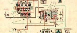
Description of the kinematic diagram of the Universal-2 screw-cutting lathe
Main drive chain
The spindle rotation speed is controlled using a step-pulley belt drive.
From the electric motor 4, rotation is transmitted to a pulley 43, which has protrusions 42 at one end that can fit into the grooves of a 3-stage pulley 44. Thus, the pulley also performs the functions of a coupling.
To obtain 6 steps of the lower range of spindle rotation speeds (140 - 950 rpm), the pulley 43 is turned over with its protrusions outward and the movement from the pulley 43 is transmitted by a V-belt 45 to a 4-speed pulley 46 and then by a V-belt 47 to a 3-speed pulley 44, freely rotating on two radial ball bearings relative to the electric motor shaft, and then using a V-belt 48 on a 4-speed pulley 19, rigidly connected to the spindle 50.
To obtain 4 stages of the upper range of spindle rotation frequencies (800 - 3000 rpm), pulley 43 with protrusions 42 enters the grooves of pulley 44, connecting it to the electric motor shaft and the movement is transmitted from pulley 43 and 44 by belts to pulley 49 and spindle 50, while belts 45 and 47 must be removed.
The spindle speed is adjusted by moving the V-belts and coupling in accordance with the adjustment table (see Fig. 16).
Feed drive chain
The mechanical feed drive chain ensures the longitudinal movement of the support during turning and thread cutting and allows for: turning on the feed “to the left” or “to the right” and turning it off without stopping the rotation of the spindle; changing the direction of movement of the support while maintaining the same direction of rotation of the spindle (cutting right-hand and left-hand threads); regulation of the feed rate and pitch of the thread being cut.
The source of movement (initial link) of the feed chain is the rotation of the spindle, therefore the feed dimension is the amount of movement of the caliper in millimeters per spindle revolution (mm/rev).
From the replaceable gear A (see Fig. 13), installed on the spindle 50, rotation is transmitted through the replaceable gears B, C, D (when configured for feed) or B, C (when configured for thread cutting) to shaft 51, gear wheels 52, 53 or gear wheels 92, 88 and 89, clutch 54 for turning on the mechanical longitudinal movement of the caliper to the left or right and turning it off, and then to the longitudinal lead screw 11.
When cutting a left-hand thread, changing the direction of movement of the caliper while keeping the direction of rotation of the spindle unchanged is achieved by installing the coupling 54 in the right position.
The amount of feed and pitch of the cut thread is regulated by selecting replaceable gears A, B, C, D or A, B, C in accordance with the setting table.
Adjusting the Universal machine
If excessive play or excessive tension appears in the spindle bearings, they must be adjusted. To do this (Fig., unscrew nuts 2 and 4, remove pulley 6 and rotate nut 5. When tightening nut 5, the clearance in the bearing decreases; when loosening, it increases. Correctly adjusted bearings should not have axial play, which can be checked by moving the spindle forward and back in the axial direction. One of the reasons for vibrations during cutting may be improper adjustment of the bearings.
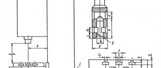
Setting up the machine for drilling, milling and grinding work and rules for its use
To reconfigure the machine for drilling, milling and grinding work, it is necessary to remove the spindle head with the drive and electric motor, for which, through the window in the wooden stand below, completely unscrew two nuts 3 (Fig. 8) with the tubular wrench supplied with the machine, and remove the two pins located in front of the spindle head. After this, secure bracket 2 (Fig. 10) to the spindle headstock with the same nuts 3. Instead of the spindle headstock, install stand I into the hole in the frame, put on washer 4 and secure nut 3 with a tubular wrench. Place bracket 2 with spindle head and drive on the rack and secure with screw 5 using a wrench. The height position of the bracket depends on the height of the workpiece and the length of the cutting tool.
Drills and end mills are fixed in a type II chuck with a diameter of 1-6 mm or in a collet I (Fig. 9). To install the chuck, it is necessary to insert a conical mandrel 6 into the conical hole of the spindle (Fig. 10), onto the free end of which the chuck is placed. When performing surface grinding work, screw the assembled grinding mandrel onto the threaded end of the spindle (Fig. 11).
The workpieces can be secured in a vice or on a rectangular table, which are installed on the upper slide of the support.
To install the vice, it is necessary to remove the tool holder, which is attached to the slide with a screw and a block located in the T-shaped groove. Using the two shorter screws and adding one block in the T-slot, screw the vise securely onto the top slide.
The vice (Fig. 12) has a screw-on jaw I, in which two mutually perpendicular grooves are made in the form of a prize, which makes it possible to conveniently fasten cylindrical parts in vertical and horizontal positions.
Installing a rectangular table (Fig. 13) is similar to installing a vice. The table is clamped with screws and four nuts supplied with the machine. The workpieces are mounted on the table using two clamps, each of which is made in the form of a strip with two screws.
When clamping, the bar should rest on the part with one end, the other end should rest on the adjusting screw and be positioned horizontally to avoid bending of the screws when clamping the part with a nut.
To ensure a closer approach of the caliper to the spindle head, it is necessary to remove the guard sleeve of the longitudinal screw, fixed on the left side of the caliper.
Vertical approach and feeding of the cutting tool is carried out by moving the sleeve in the spindle head using handle 7 (Fig. 10). In this case, using two screws located in the spindle headstock, it is necessary to pre-tighten the sleeve so that it does not fall down under the influence of its own nose and at the same time can be relatively easily placed from the handle 7. The feed when drilling should be such that it did not cause drill breakage or friction without removing noticeable chips. Before drilling holes, it is necessary to punch the workpiece and, by moving the caliper in two directions, accurately align the hole with the tip of the drill.
When milling, the vertical movement of the sleeve only involves cutting in, after which the sleeve should be secured to the spindle head using screws. Feed in the horizontal plane is carried out in two mutually perpendicular directions by moving the caliper. If it is necessary to mill along a contour, then it should first be drawn with a scriber on the surface of the workpiece.
When flat grinding, the abrasive wheel is also fed in the vertical direction only to a depth that should be small (0.01-0.02 mm). In some cases, it is possible to remove a layer of metal up to 0.5 mm deep. Feed in the horizontal direction should be carried out by the caliper evenly and quickly enough until the circle completely leaves contact with the workpiece. At the end of the treatment, to achieve good surface cleanliness, the so-called curing is done, i.e. Feeding is carried out without cutting into the grinding wheel until the spark disappears.
The grinding wheel can also be used to sharpen various tools.
Setting up the machine for sawing work and rules for its use
Sawing work is carried out on a special rectangular table (Fig. 14), in the slot of which a circular saw rotates. The machine is supplied with a saw for sawing wood or other material with similar mechanical properties. Other types of saws can cut thin metal sheets or strips.
Setting up the device is carried out as follows. Unscrew the nuts securing the spindle headstock through the window in the wooden stand, remove the spindle headstock, install a spacer, on which to install the spindle headstock again and secure it with nuts from below.
Adapter I with a fixed saw should be screwed onto the front threaded end of the spindle (Fig. 14) and tightened with a rod, inserting it into the holes of the adapter. Attach bracket 2 to the upper slide of the caliper using two screws 3 and nuts 4 located in the T-shaped grooves. After this, position the rectangular table 5 so that the saw fits into its slot and is in the middle of the cavity of the safety casing 6. Then, moving the caliper in two mutually perpendicular directions, align the holes of the table 5 and bracket 2 for fastening with screws 7. In this case, pin 8 should be free enter the hole in the bushing 9. If they do not coincide, then loosen the nut 10, insert the pin with the caliper and fasten the nut 10 again. Periodically apply 2-3 drops of oil to the friction point between the pin and the bushing. By moving the table 5 with the support in the longitudinal direction, ensure free rotation of the saw so that it does not touch the table and the safety guard. After this, secure the caliper with a specially provided screw. It is necessary that when the saw rotates, the sleeve 9 does not heat up too much due to improper adjustment of the sleeve. For convenient and correct direction of the material being cut, limiter II is used, which is secured with two screws 12. In this case, the edge of limiter II facing the saw must be installed strictly parallel to its blade.
The cutting of the material is carried out by uniformly feeding it along the saw and pressing it against limiter II.
ATTENTION! When working, be careful and keep your fingers at a sufficiently safe distance from the rotating saw. Working with the fence folded down is completely unacceptable.
Technical characteristics of the Universal-2 machine
| Parameter name | Station wagon | Universal-2 | Universal-3 | Universal-3m |
| Basic machine parameters | ||||
| The largest diameter of the workpiece above the bed, mm | 100 | 125 | 150 | 150 |
| The largest diameter of the workpiece above the support, mm | 50 | 60 | 90 | 90 |
| Maximum length of the workpiece at centers (RMC), mm | 150 | 180 | 250 | 250 |
| Recommended turning depth per pass, mm | ||||
| Maximum turning depth in one pass, mm | ||||
| Maximum cutter holder size, mm | 8 x 8 | 8 x 8 | 8 x 8 | 8 x 8 |
| Largest drilling diameter for steel, mm | 6 | 6 | 6 | 6 |
| Headstock. Spindle | ||||
| Diameter of through hole in spindle, mm | 10 | 10 | 15 | 15 |
| Attaching the chuck to the spindle | M20 | M20 | M27x2 | M27x2 |
| Spindle taper size | Morse No. 1 | Morse No. 2 | Morse No. 2 | Morse No. 2 |
| Number of speed steps for direct spindle rotation | 10 | 11 | 9 | 9 |
| Spindle direct rotation frequency, rpm | 160..2890 | 140..3000 | 200..3200 | 200..3200 |
| Diameter of lathe chuck, mm | 80 | 80 | 80 | 80 |
| Stroke of the headstock sleeve, mm | 25 | 30 | — | — |
| Caliper (transverse slider). Submissions | ||||
| Maximum longitudinal movement of the caliper carriage, mm | 160 | 160 | 215 | 215 |
| Longitudinal movement of the caliper by one dial division, mm | 0,05 | 0,05 | ||
| Maximum lateral movement of the caliper, mm | 55 | 60 | 90 | 90 |
| Transverse movement of the caliper by one division of the dial, mm | 0,05 | 0,05 | ||
| Maximum movement of the cutting slide (upper support, composite slide), mm | — | — | ||
| Scale division of the tool slide rotation scale, deg | — | — | 1 | 1 |
| Limits of longitudinal working feeds of the caliper, mm/rev | — | 0,05..0,175 | 0,05..0,175 | 0,05..0,175 |
| Limits of pitches of cut metric threads, mm | — | 0,2..2 | 0,2..2,5 | 0,2..2,5 |
| Tailstock | ||||
| Maximum movement of the quill, mm | 20 | 20 | 30 | 30 |
| Tailstock cone | Morse 1 | Morse 1 | Morse 1 | Morse 2 |
| Electrical equipment | ||||
| Rated supply voltage, V | 220 V 50 Hz | 220 V 50 Hz | 220 V 50 Hz | 220 V 50 Hz |
| Main drive electric motor, W | 120 | 250 | 370 | 550 |
| Dimensions and weight of the machine | ||||
| Machine dimensions (length width height), mm | 480 x 318 x 216 | 665 x 352 x 227 | 675 x 410 x 280 | 690 x 410 x 230 |
| Machine weight, kg | 26,5 | 38 | 60 | 62 |
- Tabletop machine Universal-2. Brief description, instruction manual, ENIMS, 1975
- Acherkan N.S. Metal-cutting machines, Volume 1, 1965
- Batov V.P. Lathes., 1978
- Beletsky D.G. Handbook of a universal turner, 1987
- Denezhny P.M., Stiskin G.M., Thor I.E. Turning, 1972. (1k62)
- Denezhny P.M., Stiskin G.M., Thor I.E. Turning, 1979. (16k20)
- Modzelevsky A. A., Muschinkin A. A., Kedrov S. S., Sobol A. M., Zavgorodniy Yu. P., Lathes, 1973
- Pikus M.Yu. A mechanic's guide to machine repair, 1987
- Skhirtladze A.G., Novikov V.Yu. Technological equipment for machine-building industries, 1980
- Tepinkichiev V.K. Metal cutting machines, 1973
- Chernov N.N. Metal cutting machines, 1988
Bibliography:
Related Links. Additional Information
- School lathes
- Manufacturers of lathes
- Classification and main characteristics of turning
- Selecting the right metalworking machine
- Multi-start thread. Methods for cutting multi-start threads on a lathe
- Graphic signs for lathes
- Friction clutch of a screw-cutting lathe
- Methodology for checking and testing screw-cutting lathes for accuracy
- Lathe spindle ends
- Lathe chucks. Varieties, features of selection and operation
- Directory of lathes
Home About the company News Articles Price list Contacts Reference information Interesting video KPO woodworking machines Manufacturers
Equipment Specifications
Compared to its predecessors, the Universal-3M lathe has improved characteristics and therefore significantly expanded capabilities compared to analogues. The accuracy class of the machine is N. According to GOST, this means that the machine is of normal accuracy and the permissible differences in linear motion are 10 microns.
Dimensions
Dimensions of turning equipment for the series in question:
- 675 x410x20 mm;
- weight – 60 kg.
When purchasing, it is important to choose the right work surface. It must fit these dimensions. It is necessary to make a calculation in order to correctly distribute the load and take into account where the greatest vibration will be.
The workpiece dimensions also have maximum allowable values depending on the location. When positioned above the bed, the largest possible diameter is 150 mm. If the workpiece is located on top, in relation to the bed, the diameter is no more than 9 cm.
The length of the workpiece structure when fixed in the centers is 250 mm. By drilling you can get a hole 6 mm in diameter.
The machine has 9 stages of rotation with speeds from 200 rpm to 3200 rpm.
Location of components
The components of this machine include:
- The drive itself.
- Fixed base.
- Spindle (front) headstock.
- Device for fastening the cutter (support).
- Stubborn grandma.
- Electrical equipment box.
The main unit of the machine is the bed and it is made by casting. All the main parts of the device are attached here.
Headstock
The headstock or spindle headstock has two supports to which the spindle is attached using bearings. This is a hollow steel structure with an internal hole. The spindle, through the operation of a pulley drive, receives 10 rotational speeds.
The front end of the spindle is equipped with an M20 thread. You can attach a lathe or driving chuck to it.
Caliper
The part has an installed cutter and moves along the longitudinal guides by 160 mm, and across by 55 mm. The support on this machine can only be moved manually, since the lead screw is not connected to the drive.