I decided to make a device for checking armatures for short-circuited turns and so on. It will be useful if you decide to repair the commutator motor and check whether it was wound correctly. A very useful thing and was once produced in the USSR. But now you won’t find it during the day with fire.
We won’t go into complex formulas, I’ll try to explain in a moment what I did. I will split the article into 2 parts. "Part one. Magnetic core." "Part two. Electricity". Then I will explain why there are 2 parts.
Part one. Magnetic core.
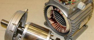
Firstly, we need a magnetic circuit, or in other words, a stator from the vacuum cleaner motor. Then we need to cut out a part in one side of it at an angle of 90 degrees, where the anchor itself will lie for testing. You can use a grinder, a saw, a spoon - whatever is more convenient for you.
Next, we need to create a platform for winding the coil. Many people write that you need to take electric cardboard or some other kind, but I don’t have it and it’s not planned in the next 50 kilometers around, there’s nowhere to buy it. This means we need an alternative. Remember, when motorcycle and car engines are being repaired and there is no gasket, it used to be cut out from the “Case No.” folder. That’s what we’ll do, but you need to keep in mind that the folder is rough, a notebook cover will do. I had a similar magnetic circuit and there was electrical cardboard, but a little narrower than needed. But it’s enough for us to measure the thickness and select an approximate one. If only there was a layer between the wire and the stator itself.
PS The device on the stator of a vacuum cleaner is inspired by a topic on one forum. The original is here. Thanks to the author for the push in the right direction.
Electrical cardboard from a different engine, but in which the windings were once placed.
and notebook cover
Now we cut:
And we wrap it in one layer on the magnetic circuit, securing the whole thing with tape:
Then we need cheeks so that the wire rests on the sides and we get a full-fledged coil. We cut them out of plywood, having previously calculated the dimensions.
And use a chisel to remove the excess. You can clean it up a little with sandpaper.
Don’t forget to take into account the angle of the stator and adjust it with the same sandpaper - a small angle on the cheeks themselves
If not, take a notebook and cut a piece of sheet to the size of the cheeks and wind it with sizing. Until the wall becomes more or less tight.
We insert the cheeks and glue them with glue. I used almost half a pack of PVAK. I glued and filled it about a dozen times. The next morning everything was ready.
Part two. Electricity.
Let's begin. We need wire. I found a wire that had once been wound from a kinescope from an old TV. The resistance immediately seemed insufficient to me - only 13 ohms, with a diameter of 0.4 with a wire length, as I later calculated 93 m. 1 mm square copper wire can withstand 3.2 -3.5 amperes. For us, if it survives half of it, it will already be happiness, this should be enough for us. I thought so.
(According to calculations (number of turns = 50 / S * 220V) on this site, I calculated the required number of turns, it turned out to be 660. But I didn’t like that this applies to all thicknesses of wires! How so?? The site seems to be good, but I’m in the calculations I doubted it, or maybe I misunderstood something.)
But then, vague doubts began to overcome me. Although I’m not an electrician, I still know from Ohm’s law (here I = UR) - if we apply 220 Volts to a conductor with a wire resistance of 13 Ohms, then a current of about 16 A will flow through it. Our wire can withstand somewhere 1.25A. In short, it will simply puff and disappear through the window. I thought and thought and attributed the rest to the miraculous magnetic saturation of the core and the inductance (energy storage) of the coil itself, which I know little about, but decided to wind it. After all, trying is not torture. And any attempt, even a failed one, is a lesson for those who want to learn.
I spent about 4-5 hours. Turn by turn, diligently. Believing less and less in success. It turned out about 800 turns.
Having finished, I went to bed and left it until the morning.
> Buy as a gift or order a unique item
- More about the author
- 15 recent entries
About Mr. Retropino
- DIY plasma lighter for gas - 04/22/2017
- Do-it-yourself ionistor dynamo flashlight - 11/20/2016
- Condenser box No. 2 - 08/31/2016
- New type headlight holder for JavaCZ motorcycle - 06/05/2016
- Do it yourself fastening for a boxing bag - 05/28/2016
- Capacitor box - 02/19/2015
- Housing for PPYA - 01/31/2015
- Anchor testing device (APD) – Working version – 01/31/2015
- Flashlight improvement - button replacement - 12/19/2014
- ƒ↓ — Anchor testing device (APD) — 12/02/2014
- UPC or collector connection device - 11/27/2014
- Project “Hot Spark” - 04/17/2014
- Vertical shelf for drills - 01/24/2014
- A simple flash drive - 12/18/2013
A device for checking the armatures of power tools and more
Hello everyone, there are many different circuit diagrams on the net for testing power tool armatures.
Each scheme has its own advantages and possibly disadvantages. I want to tell and show the operation of the circuit that I assembled quite a long time ago. In nine cases out of ten, I am able to detect an interturn short circuit in an armature, stator, or low-power pulse transformer.
Among the shortcomings, it is not possible to check the armature winding using a non-contact method...
The diagram of this device was published in the magazine RADIO 1990, number 7
The generator on transistors VT1, VT2 does not have a constant frequency; it depends on the capacitance of capacitor C1 and the tested winding (inductance) connected to the terminals XP1 and XP2 of this generator.
A variable resistor creates the necessary POS (Positive Feedback) for stable generation operation. VT4, VT5 generator with a signal amplifier, which provides three visual states of the HL1 incandescent lamp: On, blinking, off.
The operating mode depends on the bias voltage based on transistor VT4. The principle of operation of this device: If the terminals XP1 and XP2 are connected to each other, the generator on VT1 and VT2 cannot be excited and does not generate pulses. The generator on VT4, VT5 does not work, its transistors are open and the HL1 lamp glows at full intensity, signaling the integrity of the circuit (sort of a test check).
If you connect a working armature winding to the XP1 and XP2 contacts, then generation of the generator begins to occur on VT1, VT2. Using a variable resistor, we change the depth of the PIC until stable generation appears, while the bias voltage on the base of VT4 increases and the generator on VT4, VT5 starts working, the HL1 lamp blinks. The blinking frequency depends on the inductance of the coil being tested and the position of the slider of the variable resistor R1 and the depth of the PIC.
If it turns out that the winding being tested has short-circuited turns, then due to the practically lack of quality factor of the circuit, the generator on VT1, VT2 will not start, the transistor VT2 will be open and the HL1 lamp will constantly glow at full intensity, as with the short-circuited terminals XP1 and XP2.
In the event of a break, transistors VT4, VT5 will close and lamp HL1 will go out. People on the forums write that you can also check p-n junctions, but I prefer to check semiconductors with a pointer tester, if possible.
In rare cases, in the extreme position of the variable resistor R1 slider, the HL1 lamp may light up; in this case, it is necessary to slightly increase the resistance of the resistor R3 until the HL1 lamp goes out.
I didn’t like the large inertia of the incandescent lamp at a high blinking frequency; it begins to glow faintly and a false impression may be formed about the serviceability of the winding. And I simply replaced the lamp with a bright white LED, connecting it through a damping resistor (Selected depending on the type of LED available)
And of course, I had to select some denominations in my particular case in order for the circuit to work adequately. This may be due to the variation in the parameters of the transistors I use.
This circuit is very critical to the magnitude of the supply voltage; it is imperative to power it with a stabilized voltage source of 3 V
I used a classic transformer power supply with a linear voltage regulator.
Possible power supply from 3 1.5 V batteries or rechargeable batteries, always through a 3 Volt stabilizer!
Checking with a short-circuited turns indicator (SCI)
IKZ is often used to find short circuits.
Sometimes there are anchors in which the wires are not visible due to the installed bandage. In such cases, the only way to check is to use ICP devices.
First you need to make sure there are breaks and short circuits. To do this, you need to connect the tester to two adjacent lamellas and check their resistance. If it is low, then there is a short circuit.
Additional Information! Before using the IKZ, it must be configured correctly. You need to adjust the sensitivity of the device so that the red light on its panel lights up.
How to check with a multimeter
After inspecting the part, you need to check its functionality using a multimeter. This is done as follows:
- Set the resistance value to 200 ohms.
- Connect the probes of the device with adjacent lamellas and check the readings.
If the readings between adjacent plates are the same, then the winding is fully operational and there are no problems. However, sometimes during testing the resistance value drops below 1 ohm. This means that there is a short circuit between the turns.
Increased resistance may also indicate a malfunction. Most often it increases due to interturn breaks.
How to check the angle grinder's anchor for serviceability
A multimeter is a universal tool often used to check anchors.
Many people are interested in how to properly check anchors installed in angle grinders from Bosch or Interskol. Before proceeding with diagnosis, it is necessary to conduct a preliminary visual inspection. With its help you can see the visible causes of the breakdown.
For example, in this way it will be possible to determine whether the wiring has melted. If you carefully inspect the part, you may notice various dents or bent areas.
A visual inspection is also carried out to ensure that there is no solder or other conductive elements on the turns. The fact is that they often cause a short circuit, which leads to burnout of the lamellas.
How to check an anchor if there are no special tools
A 12V light bulb is suitable for checking the operation of the armature.
If it is not possible to use special devices, you can check the contacts with a 12-volt light bulb. It is inserted into the gap, after which voltage is supplied from the battery. If everything is in order with the armature, it will light up and will not go out.
In cases where the light bulb does not light, you will have to look for an open circuit or a short circuit in the stator.
DSL8240 short-circuited turn detector
Digital detector (turn-to-turn short circuit) of short-circuited turns DSL-8240L is designed to determine the integrity of the winding and the presence of short-circuited (short-circuited) turns in it. In addition, the device can be used to test the conductivity of semiconductors and the serviceability of junctions of silicon diodes and transistors. Digital detector of short-circuited turns (short-circuit turns) DSL-8240L with light and sound indication, used to check: 1) Transformer windings. 2) Windings of electric motors. 3) Inductors. 4) Line transformers. 5) Magnetic starters. 6) Contactors. 7) Relay. Chokes. 9) Serviceability of transitions of diodes and transistors. Short-circuited turn detector DSL 8240L , a compact and simple device, easy to use. ATTENTION! When working with the DSL8240L short-turn detector, the objects being tested must not be energized. Be sure to check that the objects being tested are de-energized! The manufacturer made the DSL8240L short-circuited turn detector in a splash-proof design. The manufacturer of the DSL8240L short circuit detector has equipped it with built-in test leads for ease of use and safety. There is no need to connect them to the device every time you take measurements, and disconnect them after completing the measurements. Short-circuit detector DSL8240, always ready for use. Device for checking interturn short circuit DSL8240L Russian production. The manufacturer equipped the DSL8240L interturn short circuit tester with bright LEDs and sound indication. The price of the DSL8240L is very attractive for people who have a need for it. The manufacturer of the DSL8240 made sure that the device was compact, simple and easy to use. buy the DSL8240L short-circuited turns indicator cheaply on our website. to buy the DSL8240 interturn short circuit indicator , ensuring minimal costs and ease of use of the device. Buying an interturn short circuit indicator DSL8240 is simple: send your order by email with the details of your company and the required number of devices.
Technical characteristics of the short-circuited turn detector DSL8240
| Characteristic value | |
| Supply voltage | 9 V (Krona, Corundum batteries or similar) |
| Consumption current | < 10 µA – the device is turned off. 20 mA – the device is turned on (no more). 120 mA – measurement mode (no more). |
| Tested inductance | 200 µH – 2 H |
| Indication type | light and sound |
| Working temperature | +5…+40°C |
| Climatic performance | splash-proof |
| General characteristics | |
| dimensions | 195 x 55 x 20 mm. |
| Weight (no more) | 200 g. |
| Length of connecting wires (not less) | 0.3 m. |
| Equipment | Inter-turn short-circuit indicator (short-turn indicator) DSL8240L , packaging, operating instructions, short-circuited turn detector DSL8240 . |
Do-it-yourself device for checking interturn closure
A do-it-yourself device for checking interturn closure is assembled from old Soviet components.
To assemble the tester, the following components were used and minor changes were made: transistors KT315 and KT209. Variable resistors 47 kOhm (for rough tuning) and 1 kOhm (for fine tuning). The device is powered using a KRONA battery and a 3.3V AMS1117 stabilizer. Additionally, a green LED is installed which signals that the device is turned on, and a red LED is a control LED. A 30 Ohm resistor is connected in series with both LEDs. The board has small dimensions and can fit into a compact case.
This is how the device turned out to test the turn-to-turn short circuit of inductors.
Checking the operation and integrity of the circuit.
Checking the winding. (LED flashes)
Imitation of short-circuited turns. The LED lights up at any position of the variable resistor.
Demonstration of the device operation:
comments powered by HyperComments