The TV-7 screw-cutting lathe is equipment that was specially designed to teach the basics of the lathe profession. Such machines were produced in Rostov. They equipped both educational workshops of secondary schools and workshops of professional educational institutions.
Educational screw-cutting lathe TV-7
Information about the manufacturer of the educational screw-cutting lathe TV-7
The manufacturer of the TV-7 machine was the Rostov plant of small-sized machine tools MAGSO , founded in 1956.
ComTech Financial and Industrial Group , which has existed in the machine tool equipment market for several years and has priority in the production of small-sized metal-cutting machines: lathes, milling, vibrating, sharpening, drilling, which equip schools, vocational schools, colleges, institutes, repair and installation organizations of all regions of Russia.
Machines produced by the Rostov plant of small-sized machine tools MAGSO
- NS-16 - tabletop drilling machine Ø 16
- NGF-110Sh3 - low power milling machine 0.6 kW, table size 100x400 mm
- NGF-110Sh4 - low power milling machine 0.75 kW, table size 100x400 mm
- SNVSH - tabletop drilling machine Ø 16
- SNVSH-2 - tabletop drilling machine Ø 16
- TV-4
- educational screw-cutting lathe Ø 200, RMC 350 mm - TV-6
- educational screw-cutting lathe Ø 200, RMC 350 mm - TV-6M
- educational screw-cutting lathe Ø 200, RMC 350 mm Dubno - TV-7
- educational screw-cutting lathe Ø 220, RMC 330 mm - TV-7M - educational screw-cutting lathe Ø 220 mm, RMC 275 mm
- TV-9 - educational screw-cutting lathe Ø 220 mm, RMC 525 mm
- TV-11 - educational screw-cutting lathe with frequency converter Ø 240, RMC 750 mm
TV-7 (TV7) educational screw-cutting lathe. Purpose, scope
TV-7 lathe TV-6 model in mass production
and was replaced by a more advanced model
TV-7M .
TV-7 machine (often called the “schoolboy”) is an educational universal screw-cutting lathe and is intended for all kinds of turning work in the workshops of schools for polytechnic training and cold metal cutting.
The TV-7 training machine allows you to effectively master both theoretical and practical turning skills. The machine is very popular in home workshops.
The TV-7 screw-cutting lathe allows you to perform the following types of turning work:
- Grooving and boring of cylindrical and conical surfaces
- End trimming
- segment
- Cutting 6 metric threads with a cutter
- Drilling axial holes, cutting threads with a tap and a number of other works
This machine replaced the TV-6 model, which was subjected to minor modernization. The main difference between these school machines is that they have different gearboxes and spindle heads.
The reduction gearbox of the TV-7 has two operating modes. The spindle speed is adjusted with its help, as well as by manually moving the drive belt to the required position. The TV-7 design does not provide levers for changing speeds, which were present in earlier models.
The main differences between the parameters of the TV-7 and the TV-6 model machine are as follows:
- Absence of a gearbox in the headstock of the TV-7 machine
- The presence of a two-speed reduction box in the left cabinet of the TV-7 machine
- Reduced RMC - 330 mm instead of 350 mm on the TV-6 machine
- Increased center height - 120 mm instead of 108 mm on the TV-6 machine. Accordingly, the processing damper above the bed is 220 mm and 200 mm
- The end of the spindle has a larger thread diameter - M45 x 4.5 instead of M36 x 6, hence the standard chuck is Ø125 mm instead of Ø100 mm
- More spindle rotation stages - 8 and 6
- Larger number of feeds - 6 and 3 , respectively, the number of metric threads cut
- the TV-7 machine is 400 kg , TV-6 - 300 kg, respectively.
the TV-7 screw-cutting lathe is mounted on four bearings: two angular contact bearings in the rear support and a double-row radial roller in the front.
A four-speed pulley is attached to the rear end of the spindle.
The front end of the spindle is threaded M45 x 4.5 for the intermediate flange GOST 3889 version 1 and a standard chuck Ø125 mm.
The spindle of the TV-7 lathe receives 8 rotation speeds: from a two-speed reduction gearbox and a four-speed pulley. Therefore, there is no gearbox in the headstock of the TV-7 machine; the spindle speeds are switched by transferring the drive belt and using a two-speed reduction box in the left cabinet of the machine.
Main technical characteristics of the school screw-cutting lathe TV-7
Manufacturer - Rostov-on-Don.
- The largest diameter of a Disk-type workpiece processed above the bed is Ø 220 , mm
- The largest diameter of the Shaft type workpiece processed above the upper part of the support is Ø 100 mm
- Distance between centers - 330 mm
- The longest turning length is 300 mm
- Electric motor power - 1.1 kW
- Full machine weight - 400 kg
Spindle of screw-cutting lathe TV-7
- Threaded spindle end - M45x4.5
- Spindle hole diameter - Ø 18 mm
- Spindle speed limits per minute - (8 steps) 60..1000 rpm
Feeds and threads of a screw-cutting lathe TV-7
- Limits of longitudinal feeds: — (6 steps) 0.1; 0.12; 0.16; 0.20; 0.24; 0.32 mm/rev
- Limits of metric thread pitches - (6 steps) 0.8; 1; 1.25; 1.5; 2.0; 2.5 mm
Machine design
Structurally, it consists of:
- beds;
- two cabinets;
- two grandmothers;
- calipers
The bed is the basis of the machine. It ensures the relative position of all its elements and their fastening. The cast frame is located on two pedestals. The left cabinet contains an electric motor and a reduction gearbox. On the shafts of the electric motor and gearbox there are 4 pulleys of different diameters: from smallest to largest. Moreover, a pulley of larger diameter is located near the box body, and vice versa near the engine.
In comparison with the previous model, in the TV-7 machine design, speed reduction is carried out by moving the belt to another pair of pulleys. This is ensured by a handle located on the right side of the cabinet. This ensures 4 speeds.
The gearbox contains two pairs of gears. Manual speed adjustment is provided by a handle on the front side of the cabinet. It provides clutch switching, which allows you to increase the number of speeds to 8. A distinctive feature of the TV-7 machine is the absence of handles on the headstock for setting the required spindle speeds.
Appearance of the TV-7 machine
The right cabinet contains electrical circuit components with a button for emergency (emergency) shutdown of the equipment on the front of the cabinet. This allows the mentor to turn off the machine if the student performs incorrect actions. On the side there are buttons for turning on the machine and lighting.
The support and tailstock are mounted on the frame guides. The difference in their installation is that the caliper uses external guides (prismatic and flat), and the headstock uses internal ones. A lighting lamp with a protective lampshade is placed on the support.
The design of the TV-7 includes protective elements that protect students from being damaged by shavings. These include a shield above the chuck and a transparent screen on the support, which is lowered over the part processing area. These devices are safety components.
Kinematic diagram of the TV-7 lathe
Headstock
Its design ensures placement of:
- spindle unit;
- guitars;
- feed boxes
The TV-7 headstock provides for mounting a chuck or faceplate on the spindle and installing a center. The rotational movement of the spindle is provided by two V-belts from the gearbox pulley. The spindle rests on two supports equipped with bearings. The choice was made on angular contact bearings. They ensure free rotation of the spindle and precision manufacturing of the part.
Headstock of lathe TV-7
The guitar is used to adjust the parameters of the metric thread being cut. The guitar gears receive rotation from the spindle and transmit it to the main shaft of the feed box.
The selection of the feed rate and the thread to be cut is carried out by looking at the nameplate located on the box of the same name. This is a guide for selecting feed values.
Caliper
It is used for attaching various tools and moving them relative to the workpiece along guides with given feed rates. The tool is mounted in a tool holder located in the upper part of the caliper. It can be moved manually along and across the guides using handles. The amount of movement of the tool holder can be tracked by the verniers.
The tool holder can be rotated relative to the axis by 40⁰ in each direction. To do this, unscrew the handle located above it. After turning it, it is fixed again.
TV-7 lathe support
An apron is attached to the caliper, which ensures its feeding mechanically using a drive shaft or screw. To ensure better rotation conditions, they are installed in units using bearings. Mechanical feed is activated when connecting:
- uterine split nut to the lead screw;
- jaw coupling to the drive shaft.
Tailstock
It is used to install tools and centers in quills. If there is a center, the runout of the rod is reduced and the accuracy of the part is increased. A cylindrical part is obtained when the axes of the spindle and quill coincide.
Collets, cartridges and other devices are installed in the hole with Morse taper No. 2 of the quill. The movement of the quill is carried out by a flywheel with a handle. The quill is provided with a keyway and a locking screw, in the form of a key, to prevent it from turning when moving.
Tailstock of lathe TV-7
On top of the headstock there is a handle for securing the quill. The headstock is secured by a handle located on its body.
The tailstock housing is shifted relative to the longitudinal axis, which makes it possible to obtain conical surfaces on the part.
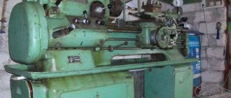
General view of the TV-7 screw-cutting lathe
Photo of the TV-7 screw-cutting lathe
Photo of the support of the TV-7 screw-cutting lathe
Photo of a guitar from a TV-7 screw-cutting lathe
Photo of the apron of the TV-7 screw-cutting lathe
Photo of the gearbox of the TV-7 screw-cutting lathe
Types of work performed on the machine
The TV-7 equipment allows you to perform the following actions:
- Cut the protrusions and depressions that are on the surface of the parts.
- You can completely cut off a certain part along a pre-made contour. It is important that he is not closed.
- Expand the distance between large and small parts made of metal. The dimensions must be verified and marked in advance.
- It is possible to grind the surface to make it smooth. You can also shape it into a cone or cylinder.
- Drill holes of any kind.
- Trim the end parts of the part that you plan to manufacture.
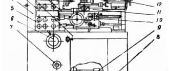
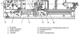
Location of TV-7 components
Location of the components of the TV-7 lathe
Specification of components of the TV-7 screw-cutting lathe
- bed
- Headstock
- Tailstock
- Caliper
- Guitar
- Apron
- Gearbox
- Two-speed reduction gearbox
- Switch
- Cabinets
- Protective casing
- Protective shields
- Lamp
- Protective screen
Documentation
The technical documentation for the TV-7 screw-cutting lathe provides a passport, which is a guide for the people working and operating it.
Download the passport (operating instructions) of the TV-7 lathe
It contains information:
- review of data on the purpose of the machine and areas of use with a description of design features;
- specifications;
- requirements for transportation and packaging indicating the scope of delivery;
- operating instructions describing the device and operating principle;
- specifications: controls;
- worm and gear wheels;
- bearings;
- electrical equipment;
Passport data is used not only at the time the machine is put into operation, but also during training to understand metalworking processes and the technology for obtaining specified part sizes.
The TV-7 screw-cutting lathe is a good educational equipment for acquiring work skills for schoolchildren and students. TV-7 is easy to operate, easy to set up, and provides the acquisition of the necessary knowledge to understand the processes of turning.
Location of controls for the TV-7 screw-cutting lathe
Location of controls for the TV-7 screw-cutting lathe
Specification of controls for the TV-7 screw-cutting lathe
- Spindle speed setting handle
- Handle for setting the feed rate and thread pitch
- Handle for turning on the lead shaft and lead screw
- Feed direction change handle
- Handle for manual movement of the cross slide
- Cutting head mounting handle
- Handle for manual movement of the upper slide
- Tailstock quill fastening handle
- Handle for attaching the tailstock to the bed guides
- Tailstock quill movement flywheel
- Rack and pinion on/off button
- Lead screw nut engagement handle
- Longitudinal mechanical feed switch handle
- Machine emergency shutdown button
- Flywheel for manual movement of the longitudinal carriage
- Electric motor reversing handle
- Batch switch for local lighting
- Batch network switch (general)
- Pulley gear belt tension handle
Mechanics of the TV-7 screw-cutting lathe
Mechanics of the TV-7 screw-cutting lathe
List of main components
The bed of the TN-1M lathe does not have stands; instead, there are low, wide legs. The main components are the same as for large floor-mounted screw-cutting lathes:
- front – spindle headstock;
- guitar;
- electric drive;
- caliper;
- movable and fixed tool holders;
- tailstock;
- The movable tool holder is mounted in the carriage and moves with the support.
Kinematic diagram
Main drive chain
Torque is transmitted to the spindle from the engine through a V-belt drive. The speed is changed by throwing the belt onto the desired pulley, including intermediate ones. The total rotation speed is 9. The switching table is located on the headstock housing.
Feed drive chain
From the spindle, rotation is transmitted to lead screws running along the bed. In the apron, the torque is converted into translational movement of the caliper. The first shaft is used for feeding during normal turning. A second shaft is used for cutting threads. Changing the direction of movement of the caliper is done by switching gears to different gears - one and a pair.
Kinematic chain of the turret
The turret head is moved manually by rotating the steering wheel connected by a shaft to a gear. Rack/. On which she rides, it is rigidly mounted on a sled. The drum has 6 screw grooves, with the help of which the drum with the tool disk is fixed.
Kinematic chain of the movable toolholder
The movable tool holder moves from the handwheel through the screw.
Fixed tool holder
The fixed tool holder moves mechanically - longitudinally along with the support. Manually moves in the transverse direction.
Tailstock kinematic chain
There is a handwheel at the end of the tailstock. When rotating it by hand. The quill moves in the tailstock housing.
Important!
In the N-1M machine model, which has a round guide, the tailstock is not removable.
This is interesting: Pliers for crimping wire lugs: crimping tool - types, features, choice
TV-7 machine control
Starting and stopping the machine's electric motor is done by handle 16 (see Fig. 3).
When turning handle 16 up, the engine rotates “Forward”; when turned down, the engine rotates “Backward”. In the middle position of the handle, the engine is turned off.
Depending on the nature of the work performed on the machine, the handles and control levers (see Fig. 3) must be in certain positions.
I. Position of handles and levers when working on thread cutting (mechanical feed with a lead screw):
- On the headstock - the position of the bit handle 4 depending on the direction of feed of the caliper (left or right)
- On the feed box - the position of handle 2 depending on the selected feed amount. Handle 3 “Screw-shaft” in the left “Screw” position
- On the apron there is the self-propelled handle 13 in the lower off position “Push”
- Rack gear engagement handle 11 - in the “Pull” position
- The handle for turning on the uterine nut 12 is in the lower extreme position.
II. Position of handles and levers when working with the drive shaft (mechanical feed):
- On the headstock - the position of the bit handle 4 depending on the direction of feed of the caliper (left or right)
- On the feed box - the position of handle 2 depending on the selected feed amount. Handle 3 “Screw-shaft” in the right “Shaft” position
- On the apron there is the self-propelled handle 13 in the “Pull” position.
- The handle for turning on the uterine nut 12 is in the upper position
- Rack gear engagement handle 11 - in the “Pull” position
III. Position of handles and levers for manual longitudinal feed:
- On the headstock - the position of the bit handle 4 is in the middle position.
- On the feed box - the position of the "Shaft-screw" lever is indifferent
- On the apron is the self-propelled handle in the off position. Lever of the master nut in the upper position
IV. The position of the control handles to obtain the required cutting conditions according to Fig. 15
Design of the TV-7 screw-cutting lathe
Machine bed
The bed is the basic unit on which, with the exception of the drive, all other components and mechanisms of the machine are mounted.
The bed is cast, cast iron, box-shaped with windows. It has two prismatic and two flat guides.
The front prismatic and rear flat guides are used to move the caliper, and the rear prismatic and front flat guides are used to move the tailstock.
The bed is installed on two machine stands.
Kinematic diagram of the TV-7 screw-cutting lathe
Kinematic diagram of the TV-7 screw-cutting lathe
Headstock of screw-cutting lathe TV-7
Headstock of screw-cutting lathe TV-7
The headstock serves to secure or support the workpiece and communicate rotational motion.
The headstock is mounted on the left side of the bed.
The movement from the gearbox via a reduction V-belt transmission through a pulley is transmitted directly to the headstock spindle.
The spindle has 8 speed levels: 60, 90, 130, 190, 350, 500, 730, 1000 rpm.
Two angular contact bearings are installed in the front and rear spindle supports.
The spindle transmits rotation of the workpiece using a three-jaw chuck or a faceplate with a driver, which are screwed onto its threaded part. When machining parts on centers, a center is inserted into the spindle.
The feed movement of the caliper is borrowed from the spindle. Shaft 9 receives rotation through gears 3—4—6—8. From shaft 9, the movement is transmitted to the guitar’s replaceable gear - 10.
A device is mounted in the headstock that allows you to change the direction of movement of the caliper - to reverse the feed. Reversal is carried out by moving gear 8 to the left and right extreme positions using handle 4 (Fig. 3). In the left extreme position, gear 8 will receive direct rotation directly from the gear block 6 located on shaft 5. In the right extreme position, gear 8 will receive reverse rotation through the idler gear 7, which is in constant mesh with the second stage of the gear block 6.
On the front side of the headstock housing there is an oil indicator 11. On the reverse side there is a plug 12 for draining the oil
Adjusting the front and rear spindle supports of a TV-7 screw-cutting lathe
Spindle supports for screw-cutting lathe TV-7
The spindle of the TV-7 machine is mounted on three bearings:
- Front bearing No. 5-3182110 GOST 7634-75 double-row radial roller, accuracy class 5, size 50x80x23 mm
- Two rear bearings No. 5-46208 GOST 831-75 single-row angular contact ball, accuracy class 5, size 40x80x18
1. Elimination of the axial play of the bearing of the front spindle support is carried out using nut 1 and lock nut 2 (Fig. 16).
If spindle vibrations occur during operation of the machine, it is necessary to check the tightness of nuts 1 and 2. If tightening the nuts does not eliminate spindle vibration, this indicates that the bearing of the front spindle support has worn out and the machine requires repair.
The gap in the bearing of the front spindle support is eliminated by grinding the ends of the compensation ring 3.
2. Elimination of the radial and axial play of the bearings of the rear spindle support is carried out by tightening nut 1 and locknut 2 (Fig. 17).
If it is not possible to eliminate the excess clearance by tightening the nuts, it is necessary to disassemble the spindle assembly and grind the ends of the compensation ring 3.
To lubricate the machine, industrial oil I-20A, GOST 20799-75 and solid oil Zh, GOST 1033-79 should be used.
The gears and bearings of the headstock are lubricated by splashing oil from the oil bath. Oil is poured in with the top cover removed.
Technical characteristics of bearing No. 3182110
Bearing 3182110 is a double row radial roller bearing, with short cylindrical rollers, with a flangeless outer ring (as a result of which the set of rolling elements on the cage is able to move and create a “floating” support), with a tapered seat bore (1:12), groove and holes for adding lubricant.
The main place of operation of such bearings is machines for various applications, units where high radial loads and speeds are applied. This standard size, like most roller bearings in this series, is currently produced only with high precision. The bearing has always been produced at the Moscow plant GPZ-1, but now its production is transferred to Volzhsky, to a branch of the Aviation Bearing Plant at 15 GPZ (all plants are united under the auspices of the European Bearing Corporation). Two modifications are produced - 4-3182110K and 2-3182110K. The letter K means the presence of an annular groove and three holes for adding lubricant. Bearings produced in the past often have the additional designation L (brass cage). Bearings with a quality guarantee should be purchased from official representatives of EPK, which are located in many regions of the country. The estimated price of new factory products is about 3,400 rubles, but a rare representative keeps them in stock. Promptly, from stock, you can mainly buy only bearings from storage, illiquid stock, used in companies of the corresponding profile.
Imported bearings of this size are designated NN3010K (the presence of the letter K in the number is mandatory, as it indicates a tapered fit). Products of different price categories are supplied to Russia: the most expensive and reliable are FAG, SKF, KOYO, IBC, the cheaper ones are NACHI and NSK. An even cheaper option is products from Eastern European manufacturers - ZKL and FLT, which are most often sold in illiquid quality, sometimes even used. The estimated price of the highest quality and most expensive bearings of this type is about 270 - 280 eurodollars.
Dimensions and characteristics of bearing 3182110 (NN3010K)
- Inner diameter (d): – 50 mm;
- Outer diameter (D): – 80 mm;
- Width (H): – 23 mm;
- Weight: – 0.426 kg;
- Roller dimensions: - 7x7 mm;
- Number of rollers: - 44 pcs;
- Dynamic load capacity: - 54 kN;
- Static load capacity: - 73.6 kN;
- Maximum rated speed: - 12000 rpm.
Bearing diagram 3182110 (NN3010K) TV-7 lathe
Technical characteristics of bearing No. 46208
Bearing 46208 is a single row angular contact ball bearing.
The type of load perceived is combined radial-axial. The bearing is one-piece. The contact angle is 26° (for the 36000 series this angle is 12°. For double-sided shaft fixation, the products are installed in pairs (since the bearings are single-row and can only carry axial load in one direction).
In our country, they are produced in Saratov at the former 3 gas processing plant (labeled SPZ). The following modifications are available: 4-46208E5, 5-46208E5, 6-46208E5, 6-46208L. In addition to the Saratov plant, they are produced by the Samara SPZ-4 (only with the sixth accuracy class), whose products are somewhat inferior to the first in quality, but are much cheaper.
Imported bearings of this type are marked 7208A. The brass separator in the number is reflected by the presence of the letter M, and the polyamide separator - the letter D.
Bearing dimensions and characteristics 46208 (7208A):
- Inner diameter (d): – 40 mm;
- Outer diameter (D): – 80 mm;
- Width (height) (H): – 18 mm;
- Weight: – 0.36 kg;
- Ball diameter: – 12.7 mm;
- Number of balls in the bearing: – 12 pcs.;
- Outer ring flange diameter: – 67.6 mm;
- Inner ring flange diameter: – 52.4 mm;
- Dynamic load capacity: – 36.8 kN;
- Static load capacity: – 21.3 kN;
- Rated speed: – 9000 rpm.
Diagram of bearing 46208 (7208A) of a TV-7 lathe
Reducing box for screw-cutting lathe TV-7
Reducing box for screw-cutting lathe TV-7
The reduction box (Fig. 6) serves to expand the speed range of the headstock spindle (see Table 5).
The box is installed in the front cabinet of the machine, on a common slide with the electric motor.
The movement from the electric motor to the input shaft 2 of the reduction gearbox is transmitted by a V-belt transmission through pulley 1. By rearranging the belt alternately into one of the streams of pulley 1 and the pulley located on the electric motor shaft, you can obtain 4 different speeds of rotation of shaft 2 (see Table 5).
The belt is loosened by turning handle 19 (Fig. 3) down towards you. After rearrangement, the belt is tightened by turning handle 19 in the opposite direction (up towards you).
Shaft 7 receives rotation through gears 3—4—5—6, or is directly connected to shaft 2 through a claw coupling made at the ends of gears 3 and 6. To do this, turn handle 1 (Fig. 3) to move gear 3 to extreme left position (engage clutch). At the same time, gears 3-4 and 5-6 disengage.
Thus, on the output shaft 7 of the reduction gearbox you can get 8 different speeds. From shaft 7 via V-belt transmission through pulley 8 the movement is transmitted to the headstock spindle.
On the front side of the reduction gearbox housing there is an oil indicator 9, on the base there is a plug 19 for draining the oil. The oil fill plug is located on the cover 11.
Guitar screw-cutting lathe TV-7
Guitar screw-cutting lathe TV-7
The guitar (transmission mechanism) (Fig. 7) is used to transmit rotation from the headstock spindle to the feed box.
In the TV-7 machine, part of the guitar gears - gears 3, 4, 6, 8 (see Fig. 5) and the feed reverse mechanism, the operation of which is described in paragraph 1.5.6., are located in the headstock housing. This arrangement made it possible to reduce the noise generated by the transmission mechanism during operation and improve its lubrication.
The gear ratio 3-4-6-8 is:
i = 48/60 * 30/48 = ½
Thus, the replacement gear of the guitar a (see Fig. 7) has half the speed in relation to the spindle.
The use of replaceable gears a (Z = 32; Z = 48; Z = 64) allows you to expand the range of cut threads and caliper feed rates.
From replaceable gear a, movement through idler gear 1 is transmitted to gear 2 located on the input shaft of the feed box. Gear 1 is installed on pin 3, pressed into bracket 4
Feed box for TV-7 lathe
Feed box for TV-7 lathe
The movement from the spindle of the headstock of the machine through the transmission mechanism (guitar) is transmitted to shaft 1 of the feed box (Fig. 8).
When turning handle 2 (Fig. 3), which has three fixed positions, block gear 6 moves along the splines of shaft 5 and its rims alternately engage with gears 2, 3, 4, stationary on shaft 1 (Fig. 8) .
This makes it possible, together with the replacement gears of the guitar, to obtain a metric thread with a pitch of 0.8; 1.0; 1.25; 1.5; 2.0; 2.5 mm and longitudinal mechanical feed of the caliper 0.10; 0.12; 0.15; 0.16; 0.18; 0.20; 0.24; 0.32 mm/rev.
The lead screw or lead roller is turned on by turning handle 3 (Fig. 3).
In the position shown in Fig. 8, the lead screw rotates.
When gear 9 moves to the right, it will disengage with gear 10 and engage with clutch 11, which transmits rotation to the running roller 7.
Thus, the design of the feed box eliminates the possibility of simultaneous rotation of the lead screw and the lead roller.
Changing the direction of rotation of the lead screw and the lead roller is done by turning handle 4 (Fig. 3).
To lubricate the feedbox mechanism, there is a tray for filling oil in its upper part.
Oil wicks onto gears and rubbing surfaces.
While the machine is operating, there should always be a small amount of oil in the feed box tray.
To drain the oil, there is a drain plug 13 at the bottom of the feed box.
When cutting threads, the lead screw should not have axial movement.
Elimination of axial play is carried out by tightening two round nuts 12.
Apron for screw-cutting lathe TV-7
Apron for screw-cutting lathe TV-7
Using the apron (Fig. 9), you can perform mechanical longitudinal feed of the caliper from the lead roller and from the lead screw, as well as manual longitudinal feed.
Manual feed is carried out by rotating the flywheel 1, mounted on the pinion shaft 4, which engages with gear 3, sitting on the shaft of rack and pinion gear 2.
The latter engages with a gear rack rigidly attached to the frame. Mechanical feed from the running roller 10 is carried out by a worm 5 connected to the roller by a sliding key. The worm rotates the worm gear 11 and then through the cam clutch and gears 13, 3 the rotation is transmitted to the rack and pinion gear. To turn on the mechanical feed, you need to turn handle 6 towards yourself, and the claw clutch is turned on.
Mechanical feed from the lead screw is carried out by turning down the handle 7, connecting the split nut 8-9 with the lead screw.
When cutting a thread, rack and pinion gear 2 must be disengaged from the rack by moving handle 12 toward you.
With mechanical feed from the running roller and with manual feed of the caliper using handwheel 1, the rack and pinion gear must be engaged with the rack by moving handle 12 away from you.
The design of the apron includes a lock that prevents the mechanical feed from the roller and the uterine nut from being turned on at the same time.
TV-7 lathe support
Machine support for screw-cutting lathe TV-7
The support (Fig. 10) is designed to secure and move the cutter; it has four slides.
Slide 1 moves in the longitudinal direction along the frame guides.
Slide 2 moves along the transverse guides of slide 1 and serves to move the cutter transversely.
Slide 4, carrying a four-position cutting head, has only longitudinal movement along the guides of slide 3, which has the ability to rotate 40° from the average position in one direction or another.
Transverse movement of slide 2 along the guides of lower slide 1 is carried out by screw 6 and nut 5.
Screw 6 is rotated by hand using handle 12.
On top, slide 2 has a recess into which the protrusion of the new part of the upper caliper fits; To secure the rotating part, there are 2 bolts, the heads of which fit into the T-shaped groove of slide 2.
The upper slide 4 of the support can be moved along the guides manually, using the handle 7, which rotates the screw 8. The guides of the frame, slides and wedges wear out so much from prolonged operation that a gap may appear between them.
As a result, the cutter will vibrate and the accuracy of the machine will decrease. To eliminate vibration, you need to adjust the clamping bars 10 of the slide 1 with screws 11.
The wedges are adjusted using screws located at the ends of slide 2 and slide 4 of the caliper.
The tool holder is secured to slide 4 with bolt 13 and handle 14. When the handle is unscrewed, the tool holder is pressed upward from the upper slide.
To fix the position of the tool holder on slide 4 there is a support pin.
The tool holder can hold up to four incisors simultaneously. The cutters are fastened with bolts 15.
Tailstock of screw-cutting lathe TV-7
Tailstock of screw-cutting lathe TV-7
The tailstock (Fig. 11) serves to support the second end of the workpiece. Housing 1 is located on base 2, which moves along the guides of the machine bed.
The quill 3 moves longitudinally in the housing.
The quill has a conical hole (Morse taper 2) into which a stop center or other tool is inserted; drills, reamers, drill chuck, etc. The quill is moved by handwheel 4, which rotates screw 5.
For ease of rotation, a handle 6 is attached to the flywheel.
To prevent the quill from turning when the handwheel rotates, it has a keyway into which a key screw 7 fits. Handle 8 is used to clamp the quill in the headstock body. The axes of the spindle and tailstock quill must coincide.
Electrical equipment of the TV-7 screw-cutting lathe
The electrical equipment of the machine includes:
- three-phase asynchronous electric motor with a power of 1.1 kW
- universal cam switch
- local lighting lamp
- electrical panel on which magnetic starters are mounted
- package switches for network and local lighting
- local lighting transformer
- circuit breakers
The panel with electrical equipment is installed in the rear cabinet of the machine.
The electric motor is located in the front cabinet.
The universal cam switch is mounted on the frame on the back side of the machine.
Design Features
The unit is designed for processing parts made of different grades of steel and “rainbow” metals using the rotational method. It can also carry out the cutting process without preheating metal products.
The main differences between the prototype lie in the design features of the front mechanism and the gearbox unit. The transformation of the operating order is carried out by transferring the belts over the rollers of the main and auxiliary shafts. All this happens when starting a downshift. As a result, three auxiliary feeds and the potential for cutting three types of metric threads were added to the functional characteristics of the device.
To correctly understand the design properties of the equipment, you need to carefully familiarize yourself with its components:
- Bearing frame. This is the base of the machine, made of cast iron, on which the remaining components of the device are included.
- Facial mechanism. The system's devices are intended for fastening the workpiece to be finished, transforming its position and imparting a rotational action to it. The drive uses a gearbox combined with a main shaft roller.
- Box with low gear. The design supplies torque to the equipment apron and ultimately creates a thread.
- Caliper. This unit is intended for fastening the cutting tool and changing its position relative to the handling workpiece.
- Rear mechanism. The design of the system is common and is intended for mounting the workpiece. It contains tools for drilling openings and holes. During operation, it is important to control the alignment of the rear mechanism quill and the axis of the main shaft.
- Three-phase asynchronous motor. Motor power 1.1 kW. An electric cam-type switch is responsible for converting the indicators.
Machine adjustment
To extend the service life of V-belt drives and make fuller use of the electric motor's power, it is necessary to monitor the tension of the belts and tighten them in a timely manner.
To tension belt 1 (see Fig. 18) of the V-belt transmission from the engine to the reduction gearbox, it is necessary to loosen locknut 2 and by rotating nut 3 to the left, move the sub-motor plate along screw 4, creating the necessary tension (10 kg per one branch at rest). Then tighten nut 2.
To tension the belt 5 of the V-belt transmission from the reduction box to the headstock, it is necessary to loosen the bolts 6 securing the slide with the reduction box to the front stand, use screw 7 to lower the slide, creating the necessary tension (10 kg per one branch of the belt at rest). After this, tighten bolts 6.
Machine care
Switching the reduction gearbox, the headstock feed reverse, as well as the feedbox handles must be done with the engine turned off after the machine has completely stopped. If the required pair of gears or gear clutch does not engage, it is necessary to hold the chuck or headstock pulley with your hand, turn the spindle and engage the gears or clutch.
When changing gears during a period of incomplete stop of the spindle, sharp impacts of toothed couplings and gears occur, as a result of which they quickly wear out and become unusable.
Before screwing the chuck onto the spindle, you need to thoroughly clean the threads on the spindle and in the chuck.
Contaminated threads cause the chuck to jam on the spindle and can damage the spindle.
It is necessary to carefully monitor the condition of the caliper seals, since over time small chips accumulate in them, which can cause scoring on the bed guides. The seals must be washed with kerosene.
The bed guides require very careful care. Under no circumstances should you allow a dirty mark to remain on the guides when the caliper moves. The layer of oil on the bed guides must always be clean when the caliper moves.
If a dirty mark appears, you should immediately thoroughly rinse the guides with kerosene.
A dirty mark is formed by tiny particles of metal that get between the rubbing surfaces of the caliper and the frame and, when the caliper moves, form scratches on the guides.
Particular attention must be paid to not overload the machine. An overloaded machine will experience increased noise during operation, belt slipping, overheating of the spindle bearings and overheating of the motor.
When turning parts in the centers, the quill should be extended a small amount; this will protect it from premature wear and provide a more durable fastening of the part.
Exploitation
The operating instructions draw attention, first of all, to the need to comply with safety measures. Basic Rules:
- Install the equipment on a rigid foundation; check the level of the installation with a level. The accuracy of the work largely depends on correct installation;
- reliably ground the machine in accordance with the requirements;
- use a wooden lattice as a stand;
- fasten the workpieces securely;
- use cutters with proper sharpening;
- secure the part in the chuck so that the cams grip it to the maximum possible extent;
Cartridge, the guides are clearly visible in the photo
- do not screw the cartridge by sudden braking;
- fasten in the chuck without emphasis on the center of the rear centered parts no more than two diameters long. For longer lengths, use the center;
- Having installed the parts in the centers, check the fixation of the tailstock;
- remove shavings in a timely manner using a crochet hook.
Machine care
For reliable and durable operation, the following rules must be followed:
- Before making switches, the machine must be completely stopped. If the gear pair does not engage or the gear clutch does not engage, turn the chuck by hand until the gears or clutch engage. Switching when the machine is not completely stopped leads to impacts, which causes rapid wear and breakage of gears and couplings.
- When installing the cartridge, clean the threads. Contaminated threads lead to chuck jamming and spindle breakage.
- Caliper seals require maintenance. Chips gradually accumulate in them, which damages the guides.
- Make sure that after the caliper there is no dirty mark on the guides. If a dirty mark becomes noticeable, it is washed off and the guides are lubricated with clean oil.
- The machine should not be overloaded. Overload causes increased noise, belts slip, bearings and the electric motor overheat.
- If the part is machined in the centers, the quill is extended to the smallest amount: the fastening will be secured more firmly, and the quill will last longer.
You can watch a video about working on the TV-7 lathe
Lubrication
Timely lubrication guarantees trouble-free, long-lasting operation . Rubbing parts, screws, shafts, gears, bearings are subject to lubrication. The following components are lubricated:
- Headstock through the top cover. An oil level indicator is used to control the level.
- Reducing box through a plug. An oil level indicator is used to control the level.
- Feed box through the tray at the top. From there it is fed through wicks to the rubbing surfaces and gears. There should always be some oil in the trough. The accumulated oil is drained through the plug from below.
- Guitar: Grease is used to lubricate the gears and bushing.
- On the bed, all mechanisms, bearings, and guides are lubricated manually before starting work.
- Everything in the apron is lubricated through the hole at the bottom of the caliper. Lubrication is carried out every time before starting work.
- Everything in the caliper is lubricated by hand before work.
- Tailstock. Lubricate the quill and the screw support before work.
Main technical characteristics of the TV-7 machine
| Parameter name | TV-4 | TV-6 | TV-7 |
| Basic machine parameters | |||
| Accuracy class | N | N | N |
| The largest diameter of the workpiece above the bed, mm | 200 | 200 | 220 |
| The largest diameter of the workpiece above the support, mm | 125 | 80 | 100 |
| Height of centers above flat bed guides, mm | 108 | 108 | 120 |
| Maximum length of the workpiece at centers (RMC), mm | 350 | 350 | 330 |
| Maximum length of the workpiece in the chuck, mm | 310 | ||
| Diameter of the workpiece installed in the chuck, mm | 5..110 | ||
| Maximum turning length, mm | 300 | 300 | 300 |
| Maximum height of the cutter holder, mm | 10 x 12 | 12 x 12 | 16 x 16 |
| Height from the cutting surface to the center line, mm | 12 | 12 | |
| The greatest distance from the axis of the centers to the edge of the tool holder, mm | 78 | 78 | |
| Headstock. Spindle | |||
| Threaded end of spindle, mm | M36 x 4.5 | M36 x 4.5 | M45 x 4.5 |
| Diameter of standard cartridge, mm | 100 | 100 | 125 |
| Diameter of through hole in spindle, mm | 16 | 18 | |
| Maximum rod diameter, mm | 15 | 12 | |
| Morse taper spindle | №2 | №3 | №3 |
| Number of speed steps for direct spindle rotation | 6 | 6 | 8 |
| Spindle direct rotation frequency, rpm | 120, 160, 230, 375, 500, 710 | 130, 170, 235, 385, 510, 700 | 60,90, 130, 190, 350, 500, 730, 1000 |
| Spindle braking | No | No | No |
| Handle lock | No | No | No |
| Caliper. Submissions | |||
| Maximum longitudinal movement of the caliper, mm | 300 | 300 | 260 |
| Longitudinal movement of the caliper by one dial division, mm | 0,5 | 0,25 | 0,25 |
| Maximum lateral movement of the caliper, mm | 100 | 100 | |
| Transverse movement of the caliper by one division of the dial, mm | 0,025 | 0,025 | 0,025 |
| Maximum movement of the cutting slide, mm | 50 | 85 | 85 |
| Movement of the cutting slide by one division of the dial, mm | 0,025 | 0,025 | 0,025 |
| Angle of rotation of the cutting slide, degrees | ±45° | ±45° | ±40° |
| Number of stages of longitudinal feed of the caliper | 3 | 3 | 6 |
| Limits of longitudinal working feeds of the caliper, mm/rev | 0,08; 0,1; 0,12 | 0,08; 0,1; 0,12 | 0,1; 0,12; 0,16; 0,20; 0,24; 0,32 |
| Limits of working cross feeds of the caliper, mm/rev | No | No | No |
| Number of metric threads to be cut | 3 | 3 | 6 |
| Limits of pitches of cut metric threads, mm | 0,8; 1,0; 1,25 | 0,8; 1,0; 1,25 | 0,8; 1,0; 1,25; 1,5; 2,0; 2,5 |
| Limits of pitches of cut inch threads | No | No | No |
| Limits of pitches of cut modular threads | No | No | No |
| Limits of pitches of cut pitch threads | No | No | No |
| Tailstock | |||
| Morse taper tailstock | №2 | №2 | №2 |
| Maximum movement of the quill, mm | 65 | 65 | 65 |
| Electrical equipment | |||
| Main drive electric motor, kW | 1,0 | 1,1 | 1,1 |
| Dimensions and weight of the machine | |||
| Machine dimensions (length width height), mm | 1440 x 470 x 1020 | 1100 x 470 x 110 | 1050 x 535 x 1200 |
| Machine weight, kg | 280 | 300 | 400 |
- Screw-cutting lathe (training), model TV-7. Passport, 1988
- Acherkan N.S. Metal-cutting machines, Volume 1, 1965
- Batov V.P. Lathes, 1978
- Beletsky D.G. Handbook of a universal turner, 1987
- Denezhny P.M., Stiskin G.M., Thor I.E. Turning, 1972. (1k62)
- Denezhny P.M., Stiskin G.M., Thor I.E. Turning, 1979. (16k20)
- Lokteva S.E. Computer controlled machines, 1986
- Modzelevsky A. A., et al. Lathes, 1973
- Pikus M.Yu. A mechanic's guide to machine repair, 1987
- Skhirtladze A.G., Novikov V.Yu. Technological equipment for machine-building industries, 1980
- Tepinkichiev V.K. Metal cutting machines, 1973
- Chernov N.N. Metal cutting machines, 1988
Bibliography:
Related Links. Additional Information
- Classification and main characteristics of turning
- Selecting the right metalworking machine
- Multi-start thread. Methods for cutting multi-start threads on a lathe
- Graphic signs for lathes
- Friction clutch of a screw-cutting lathe
- Lathe repair technology. Repair of bed and support guides
- Lathe repair technology. Repair of headstock and tailstock
- Lathe spindle repair
- Methodology for checking and testing screw-cutting lathes for accuracy
- Directory of lathes
- Manufacturers of lathes
Home About the company News Articles Price list Contacts Reference information Interesting video KPO woodworking machines Manufacturers