Information about the manufacturer of the screw-cutting lathe 1P611
1P611 screw-cutting lathe is Odessa SKB-3, 1961.
The manufacturers of the 1P611 are two machine-tool plants of the USSR, the Odessa Experimental Mechanical Plant and the Srednevolzhsky Machine-Tool Plant SVSZ , founded in 1876.
The production of metal-cutting machines at the Srednevolzhsky Machine Tool Plant first began at the end of January 1926. The first machine produced at the enterprise was a screw-cutting lathe with a stepped pulley, model TV-155V.
During the war years, the plant mastered the production of a screw-cutting lathe 1615
and soon upgraded it, bringing the spindle speed to 1000 rpm.
In 1949, the machine was put into mass production 1616
, in the sixties the models were
1B616 and 1A616
, and from the beginning of the seventies the production of the
16B16 .
Since the 90s of the last century, the SVSZ company has been producing lathes under the SAMAT .
Machine tools manufactured by the Srednevolzhsky Machine Tool Plant, SVSZ, Samara
- 1A616
universal screw-cutting lathe Ø 320 - 1A616k
screw-cutting lathe with automatic transmission Ø 320 - 1A616p
high-precision screw-cutting lathe Ø 320 - 1B811
turning and backing machine Ø 250 - 1E811
turning and backing machine Ø 250 - 1P611
universal screw-cutting lathe Ø 250 - 16B16
universal screw-cutting lathe 320 - 16B16P
universal screw-cutting lathe with increased precision Ø 320 - 16B16KP
universal high-precision screw-cutting lathe with automatic transmission Ø 320 - 16B16F3
chuck center lathe with CNC Ø 320 - 16B16T1
CNC lathe Ø 320 - 1615
universal screw-cutting lathe Ø 320 - 1616
universal screw-cutting lathe Ø 320 - 1716PF3
CNC lathe Ø 320 - 5350A
semi-automatic slot milling machine Ø 150 - Samat 400
universal high-precision screw-cutting lathe Ø 320 - Craftsman
table lathe Ø 175
Brief information about the manufacturer
The design team of the Odessa Machine Tool Plant has developed a new screw-cutting lathe. It differed from its analogues in its high processing accuracy. In 1968, model 1P611 was put into production.
The design documentation was transferred to the Saratov Machine Tool Plant. The machines were produced at the same time and actually differed only in the nameplate on the headstock. It indicated the name of the manufacturing plant.
After 1995, machine tool factories in Odessa were privatized and production decreased. Currently, only part of the workshops is operating. They make presses for making bricks and produce woodworking machines.
The Saratov plant continues to produce lathes and other high-precision metalworking equipment under the Samat brand. Simple manual models are a thing of the past. Now at the SVSZ - Srednevolzhsky plant, they produce CNC machines and automated lines.
1P611 High-precision universal screw-cutting lathe. Purpose and scope
The developer of the screw-cutting lathe 1P611 is Odessa SKB-3 . Start of mass production - 1961.
The universal screw-cutting lathe 1P611 of increased precision of the tool group is designed to perform a wide variety of work on centers, collet or jaw chucks for ferrous and non-ferrous metals, including turning cones, as well as for cutting metric, modular, and inch threads
1P611 lathe is used for finishing and semi-finishing work in single and small-scale production. The machines are intended for use primarily in multi-storey buildings, as well as in mobile repair shops and ships.
Machine 1P611 provides:
- Various turning operations in centers, collet and jaw chucks;
- A wide range of speeds and feeds ensures productive processing with good surface quality;
- milling work, as well as processing with an end tool installed in a drill chuck;
- External and internal grinding of parts in centers and chucks.
Lathe designation
1
— lathe (group number according to ENIMS classification)
P
– machine generation (A, B, C, D, K, L, P)
6
– subgroup number (1, 2, 3, 4, 5, 6, 7, 8, 9) according to the ENIMS classification (6 - screw-cutting lathe)
11
– height of centers above the bed (11, 16, 20, 25, 30, 40, 50) (11 – height of centers 135 mm)
Letters at the end of the model designation:
G
– a machine with a recess in the bed
TO
– a machine with a copying device, with an automatic gearbox
P
– machine accuracy - (n, p, v, a, s) according to GOST 8-82 (P - increased accuracy)
F1
– a machine with a digital display device (DRO) and preset of coordinates
F2
– machine with CNC positional numerical control system
F3
– machine with contour (continuous) CNC system
F4
– multi-purpose machine with CNC contour system and tool store
Adjusting spindle bearings
To adjust the radial clearance of a double-row roller bearing of the front spindle support, you must:
- adjust using nut 8
- The recommended value of the radial clearance in the bearing is 0.005 mm
- Eliminate the axial play of the spindle by grinding the spacer rings of the front support, followed by tightening nut 8, which after adjustment is secured with screws
Grind the spacer half rings to the size determined by the formula:
A = B - δ mm,
Where
B is the thickness of the removed half rings before grinding, mm;
δ is the amount of required displacement of the inner ring of the bearing δ relative to the spindle journal.
The displacement value δ is determined by the formula:
δ = 15(Δо - Δ 0.01) mm,,
Where
Δо - initial radial clearance (before adjustment), mm; Δ is the required radial clearance of the bearing, mm.
Screw-cutting lathe 1P611 is supplied with radial clearance Δ = 0.003 to 0.005 mm.
Technical characteristics of bearing No. 3182111
Bearing 3182111 is a double row radial roller bearing, with short cylindrical rollers, with a flangeless outer ring (as a result of which the set of rolling elements on the cage is able to move and create a “floating” support), with a tapered seat bore (1:12), groove and holes for adding lubricant.
The main place of operation of such bearings is machines for various applications, units where high radial loads and speeds are applied. This standard size, like most roller bearings in this series, is currently produced only with high precision. The bearing has always been produced at the Moscow GPZ-1 plant, but now, unfortunately, it has been discontinued and you can buy it directly only from companies that sell bearings from storage, surplus stock, used, and cleaned. You can find products of 2, 4, 5 and 6 accuracy classes. The designation to the right of the number is most often L (brass separator, old). The price of bearings greatly depends on their accuracy and safety class, from 300 to 2300 rubles.
Imported bearings of this size are designated NN3011K (the presence of the letter K in the number is mandatory, as it indicates a tapered fit). Products of different price categories are supplied to Russia: the most expensive and reliable are FAG, SKF, KOYO, IBC, the cheaper ones are NACHI and NSK. An even cheaper option is products from Eastern European manufacturers - ZKL and FLT, which are most often sold in illiquid quality, sometimes even used. The estimated price of the highest quality and most expensive bearings of this type is about 275 euros.
About other machines: Laser machine WATTSAN 6090 LT—Lifting table buy at prices from the manufacturer—LaserCut
Dimensions and characteristics of bearing 3182111 (nn3011k)
- Inner diameter (d): – 55 mm;
- Outer diameter (D): – 90 mm;
- Width (H): – 26 mm;
- Weight: – 0.623 kg;
- Roller dimensions: - 8x8 mm;
- Number of rollers: - 44 pcs;
- Dynamic load capacity: - 70.5 kN;
- Static load capacity: - 97.5 kN;
- Maximum rated speed: - 11000 rpm.
Bearing diagram 3182111 (NN3011K) lathe 1P611
Photo of bearing 3182111 of a screw-cutting lathe 1P611
Technical characteristics of bearing No. 36210
Bearing 36210 is a single row angular contact ball bearing.
The type of load perceived is combined radial-axial. For rigid fixation of the shafts of machines that require high precision processing of parts, they are installed in pairs. In this case, bearings are selected with high degrees of accuracy (T or 2 and 4). The bearing is one-piece with a bevel on the outer ring. The contact angle of the 36000 series is 12°. In the Russian Federation it is produced in factories:
- SPZ-4 (Samara) - modifications 6-36210 E and 6-36210 L (the first is a polyamide separator, the second is brass), assembled from components produced in China;
- ZAP (Samara) - modifications T-36210 E, 4-36210 E, 5-36210 E, good quality bearings, production of “duplexes” is also possible;
- 3 GPZ (Saratov) - modifications 5-36210E5, 6-36210E, 4-36210 L, 6-36210L - similar in quality and configuration to ZAP, since both plants are part of the European Bearing Corporation.
There are sets of two bearings for rigid fixation of the shaft: double 336210 and double tandem 436210. The latter is the “driving force” of our bearing factories, since it is installed on the spindles of metalworking machines operating there and is consumed in very large volumes.
Foreign-made bearings of this type have the number 7210CD.
Dimensions and characteristics of bearing 36210 (7210):
- Inner diameter (d): – 20 mm;
- Outer diameter (D): – 90 mm;
- Width (height) (H): – 20 mm;
- Weight: – 0.47 kg;
- Ball diameter: – 12.7 mm;
- Number of balls in the bearing: – 14 pcs.;
- Outer ring flange diameter: – 77.9 mm;
- Inner ring flange diameter: – 61.8 mm;
- Dynamic load capacity: – 43.2 kN;
- Static load capacity: – 27 kN;
- Rated speed: – 11000 rpm.
Diagram of bearing 36210 (7210) of a 1P611 lathe
Landing and connecting bases for lathe 1P611
Landing and connecting bases for lathe 1p611
Screw-cutting lathe bed 1p611
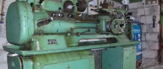
General view of the screw-cutting lathe 1P611
Photo of screw-cutting lathe 1p611
Apron for screw-cutting lathe 1p611
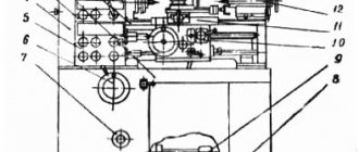
Location of components of screw-cutting lathe 1P611
Location of the main components of the lathe 1p611
Specification of components of screw-cutting lathe 1P611
- Bed - 10
- Cabinet - 15
- Gearbox - 20*
- Control mechanism - 22
- Headstock - 25
- Guitar - 30
- Feed box - 35
- Apron – 40
- Caliper - 45
- Tailstock - 50
- Cone ruler – 52*
- Cooling - 55
- Fixed steady rest – 60*
- Movable steady rest – 61*
- Accessories - 62*
- Fencing – 70*
- Electrical equipment - 80
- Switch - 82
Types of failures of lathes
In most cases, the structure of lathes is the same:
- bed;
- spindles;
- working grandmother.
In this case, scraping of workpieces is usually carried out in a horizontal plane. If we analyze screw-cutting lathes, they differ from simple ones in that they have front and rear working headstocks, a support, a bed with an extension and a feed box. The following malfunctions occur in the equipment:
- Based on practice, the spindle speed control module breaks first. Tapered roller bearings, which are used in many machines, are subject to the greatest degree of wear. From time to time, adjustment and replacement of bearings is necessary, which directly depends on the lubrication system and type of machine.
- The next most common breakdown is a malfunction of the caliper locking holder. In this case, the part being processed moves unevenly, both in the transverse and longitudinal directions.
All lathes vary in size, design and type of workpieces. There are semi-automatic and automatic devices. The latter, as a rule, work much longer, since when feeding manually, the size of the head and the degree of its turning are often not calculated correctly.
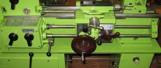
Location of controls for screw-cutting lathe 1P611
Location of controls for lathe 1p611
Specification of controls for screw-cutting lathe 1P611
- Input switch
- Light switch
- Cooling switch
- Overload clutch handle
- Handle for turning on mechanical longitudinal and transverse movement
- Manual cross handle
- Manual longitudinal movement handle
- Handle for turning on and off handwheel rotation
- Tool holder clamp handle
- Handwheel for changing the spindle speed
- Handle for changing the direction of spindle rotation and braking
- Feed selector handle
- Feed selector handle
- Collet clamp handwheel
- The handle of the snaffle and the inclusion of the uterine nut
- Thread to feed switch handle
- Leadscrew and shaft shift handle
- Handle busting
- Quill clamp handle
- Handwheel for moving the quill
- Upper carriage handle
- Headstock clamp handle
- Oil pump handle
Design of the main components of the screw-cutting lathe 1P611
The machine consists of the following components: bed, stand, gearbox, headstock, guitar, feed box, apron, caliper, rear headstock, cooling system, accessories, fence, electrical equipment and switch.
bed
The bed is installed and fixed on the machine stand, has prismatic guides for the support, a plane and a prism for the tailstock. Between the guides there are oval windows for pouring out chips. The side walls of the frame are connected by transverse U-shaped ribs. The left side of the bed is expanded at the location where the headstock is installed.
The headstock is installed on machined plane 1 (Fig. 8), coinciding with the plane of the front guide.
Installation of the machine spindle parallel to the bed guides is achieved by pressing the thrust protrusions of the headstock to the vertical machined plane of the guides 4.
The headstock is secured to the frame with four screws.
Plane 3 is used to mount the feed box, rack and rear bracket.
For the passage of belts, there is a ledge 2 on the front wall. On both sides of this ledge there are openings for the feed box housing. A lead screw 7 and a lead roller 6 are connected to the feed box, the right ends of which are mounted in the rear bracket 5 of the frame.
Cabinet
The machine stand is of welded construction.
The lower and upper parts of the cabinet are rigid frames 3 and 8 (Fig. 9) made of corners, to which thin sheets (sheathing) are welded.
A gearbox is mounted in the cabinet, on the tensioner plate 7. There are rubber gaskets 6 between the plate and the gearbox to reduce vibrations transmitted to the machine from the gearbox. At the back, the tensioner plate is closed with a cover 5 made of sheet material.
On the left side of the cabinet, through an oval window in the front wall, the gearbox speed control is located. An original switch with a handle for controlling the rotation of the electric motor is attached to the front left of the cabinet. In the front part of the cabinet there is a niche for the worker’s feet. On the right side of the cabinet there is an electrical equipment cabinet 4, and the switch handles are located on its front wall.
Between the electrical cabinet and the gearbox there is a cooling tank with an electric pump. A thin-sheet welded trough 1 is welded to the top of the cabinet, in which chips and coolant are collected when working with cooling. The coolant is drained through filter 2 troughs into the cooling tank. The filter is easily removed for cleaning.
Gearbox
Gearbox of screw-cutting lathe 1p611
The gearbox consists of an 8-speed gearbox, control mechanisms and lubrication.
Rotation is transmitted to the gearbox from an electric motor flanged to the gearbox housing. The gearbox mechanisms transmit eight different speeds to the output pulley 15 (Fig. 10) - the denominator of the geometric progression series is 1.41. The mobile gear units 5, 6, 9, 10, 11 are controlled using disk 2 with grooves at the ends. The grooves include lever rollers 1, 3, 4; the levers move the forks 16, 17 and 19, sitting on the rod 18. From the first roller 12 of the gearbox, the roller with the eccentric gear 14 rotates. The eccentric gear drives the plunger pump 13; from the latter, lubricant is supplied to the headstock, from where it drains through cover 7 into the oil bath of the gearbox 8, located on top, and lubricates the gearbox mechanisms. The gearbox together with a flanged electric motor is attached to the tensioner plate. By rotating the handwheel 21 along the dial 20, the required spindle rotation speed is set.
Headstock
Headstock of screw-cutting lathe 1p611
The front headstock is installed and secured to the top left of the frame. It contains spindle 5 (Fig. 11), gear 3, 4, feed drive and control mechanism. Rotation is transmitted to the spindle from pulley 2 directly when the gear coupling 9 is engaged or through overdrive. The gear ratio is 1:8. The machine spindle receives 14 different rotation speeds ranging from 33.5 to 3000 rpm with a row denominator of 1.41. The front spindle support is equipped with a double-row roller bearing 6, which takes up radial loads, and two angular contact ball bearings 7, which take up axial loads. Radial ball bearing 1 is installed in the rear spindle support.
The rear support of the spindle and drive pulley is located in bracket 11, molded to the headstock body, and is designed in such a way that it makes it possible to change belts without disassembling the spindle. The feed drive receives rotation from a gear located on the spindle and reduces the rotation speed of the first shaft of the guitar 10. The headstock feed drive ensures reversal of the guitar when cutting right-hand and left-hand threads.
The movable gears and clutches of the headstock are controlled by handle 12 located on the front wall of the headstock housing. The control of the gear coupling and gearing is interlocked by a disk with an end groove to avoid damage.
The product is clamped using a collet clamp.
The headstock mechanisms are lubricated by the gear pump using a tubular oil distributor. To control the flow of lubricant, an oil indicator is installed on the front wall of the headstock.
Spindle bearings for screw-cutting lathe 1P611
The spindle of the 1P611 machine is mounted on 4 bearings:
- 10. Front bearing No. 3182111 GOST 7634-56 double-row radial roller, accuracy class A(4), 55x90x26
- 11. Bearing No. 36210 GOST 831-62 angular contact ball, accuracy class A(4), 50x90x20
- 8. Rear bearing No. 207 GOST 8338-57 radial ball, accuracy class B(5), 35x72x17
Adjusting spindle bearings
To adjust the radial clearance of a double-row roller bearing of the front spindle support, you must:
- adjust using nut 8
- The recommended value of the radial clearance in the bearing is 0.005 mm
- Eliminate the axial play of the spindle by grinding the spacer rings of the front support, followed by tightening nut 8, which after adjustment is secured with screws
Grind the spacer half rings to the size determined by the formula:
A = B - δ mm,
Where
B is the thickness of the removed half rings before grinding, mm;
δ is the amount of required displacement of the inner ring of the bearing δ relative to the spindle journal.
The displacement value δ is determined by the formula:
δ = 15(Δо - Δ + 0.01) mm,,
Where
Δо - initial radial clearance (before adjustment), mm; Δ is the required radial clearance of the bearing, mm.
Screw-cutting lathe 1P611 is supplied with radial clearance Δ = 0.003 to 0.005 mm.
Technical characteristics of bearing No. 3182111
Bearing 3182111 is a double row radial roller bearing, with short cylindrical rollers, with a flangeless outer ring (as a result of which the set of rolling elements on the cage is able to move and create a “floating” support), with a tapered seat bore (1:12), groove and holes for adding lubricant.
The main place of operation of such bearings is machines for various applications, units where high radial loads and speeds are applied. This standard size, like most roller bearings in this series, is currently produced only with high precision. The bearing has always been produced at the Moscow GPZ-1 plant, but now, unfortunately, it has been discontinued and you can buy it directly only from companies that sell bearings from storage, surplus stock, used, and cleaned. You can find products of 2, 4, 5 and 6 accuracy classes. The designation to the right of the number is most often L (brass separator, old). The price of bearings greatly depends on their accuracy and safety class, from 300 to 2300 rubles.
Imported bearings of this size are designated NN3011K (the presence of the letter K in the number is mandatory, as it indicates a tapered fit). Products of different price categories are supplied to Russia: the most expensive and reliable are FAG, SKF, KOYO, IBC, the cheaper ones are NACHI and NSK. An even cheaper option is products from Eastern European manufacturers - ZKL and FLT, which are most often sold in illiquid quality, sometimes even used. The estimated price of the highest quality and most expensive bearings of this type is about 275 euros.
Dimensions and characteristics of bearing 3182111 (NN3011K)
- Inner diameter (d): – 55 mm;
- Outer diameter (D): – 90 mm;
- Width (H): – 26 mm;
- Weight: – 0.623 kg;
- Roller dimensions: - 8x8 mm;
- Number of rollers: - 44 pcs;
- Dynamic load capacity: - 70.5 kN;
- Static load capacity: - 97.5 kN;
- Maximum rated speed: - 11000 rpm.
Bearing diagram 3182111 (NN3011K) lathe 1P611
Photo of bearing 3182111 of a screw-cutting lathe 1P611
Technical characteristics of bearing No. 36210
Bearing 36210 is a single row angular contact ball bearing.
The type of load perceived is combined radial-axial. For rigid fixation of the shafts of machines that require high precision processing of parts, they are installed in pairs. In this case, bearings are selected with high degrees of accuracy (T or 2 and 4). The bearing is one-piece with a bevel on the outer ring. The contact angle of the 36000 series is 12°. In the Russian Federation it is produced in factories:
- SPZ-4 (Samara) - modifications 6-36210 E and 6-36210 L (the first is a polyamide separator, the second is brass), assembled from components produced in China;
- ZAP (Samara) - modifications T-36210 E, 4-36210 E, 5-36210 E, good quality bearings, production of “duplexes” is also possible;
- 3 GPZ (Saratov) - modifications 5-36210E5, 6-36210E, 4-36210 L, 6-36210L - similar in quality and configuration to ZAP, since both plants are part of the European Bearing Corporation.
There are sets of two bearings for rigid fixation of the shaft: double 336210 and double tandem 436210. The latter is the “driving force” of our bearing factories, since it is installed on the spindles of metalworking machines operating there and is consumed in very large volumes.
Foreign-made bearings of this type have the number 7210CD.
Dimensions and characteristics of bearing 36210 (7210):
- Inner diameter (d): – 20 mm;
- Outer diameter (D): – 90 mm;
- Width (height) (H): – 20 mm;
- Weight: – 0.47 kg;
- Ball diameter: – 12.7 mm;
- Number of balls in the bearing: – 14 pcs.;
- Outer ring flange diameter: – 77.9 mm;
- Inner ring flange diameter: – 61.8 mm;
- Dynamic load capacity: – 43.2 kN;
- Static load capacity: – 27 kN;
- Rated speed: – 11000 rpm.
Diagram of bearing 36210 (7210) of a 1P611 lathe
Guitar
The guitar consists of a body 3 (Fig. 12), which is attached to the headstock, a ramp 4 and a cover 1. The ramp rotates on the flange of the headstock output roller and is secured in the desired position with a bolt 5. The axes of the replaceable gears are fixed in the groove of the ramp. It is possible to install various sets of replaceable gears that provide the feed drive settings listed in table. 2. In addition, other settings are possible.
Guitar replacement gears are designed for cutting various threads. Consists of a housing attached to the headstock and tilt box and cover. The tilt rotates on the flange of the headstock output shaft and is fixed in the desired position with a bolt. Customization of the feed drive is ensured by installing various sets of replaceable gears.
Gearbox
Feed box for screw-cutting lathe 1p611
Feed box for screw-cutting lathe 1p611
The feed box ensures that the range of cut threads and feeds specified in the technical specifications is obtained.
The feed box body contains a pitch change mechanism 1 (Fig. 13), a multiplying mechanism 3 and control mechanisms 2. The rotation of the first roller of the feed box is transmitted by the guitar. Each of these mechanisms is controlled by disks 7 and 8 with an end groove. To cut precise threads, bypassing the feedbox mechanisms, a direct connection of the lead screw to the guitar is provided. The control handles for the pitch change mechanism 4, the multiplying mechanism 5 and the activation of the lead screw and the lead roller 6 are located on the front side of the box. Feedbox lubrication is wick. Lubricant is poured through the top cover.
Caliper
Support for screw-cutting lathe 1p611
The longitudinal slide of the support 2 (Fig. 14) moves along two prismatic guides of the frame. An apron is attached to the bottom of the longitudinal slide. From above, along the guides of the longitudinal slide, the transverse slide 7 is moved using screw 1. On top of the transverse slide there is a rotary slide 5 with an upper carriage 4 and a four-position tool holder 8, which has four fixed positions.
Ball grease nipples are installed to lubricate the caliper bearings.
Apron
Apron for screw-cutting lathe 1p611
Apron for screw-cutting lathe 1p611
The apron imparts longitudinal movement to the caliper and transmits rotation to the transverse feed screw. When cutting a thread, the movement is transmitted using a nut; when grooving, it is transmitted by a rack and pinion gear.
Rotation of the rack and pinion gear 8 (Fig. 15) from the roller is transmitted by an overload mechanism, a snaffle and intermediate gears.
The reloading mechanism consists of a cradle 18 sitting on the bushings 1 of the running roller, a gear pair 2-3, a worm gear, a lock 16 and a shift handle 4. As the longitudinal feed force increases, the force pushing the worm out of engagement with the worm wheel 19 increases. turn the cradle. To rotate the cradle, it is necessary to overcome the force of the clamp spring 15, the adjustment of which determines the largest value of the longitudinal feed. When overloaded, the cradle rotates, compressing the latch spring; the latch 16 falls into the upper groove of the tile 17, fixed to the cradle, and removes the worm from engagement with the worm wheel 19, the longitudinal movement stops. To turn on the overload mechanism, you need to pull up handle 4, located on the right on the side wall of the apron.
On the same axis with the worm wheel there is a swing arm 7 of the bit of the idler gear 13.
The snaffle transmits rotation from the worm wheel to the rack and pinion or cross feed screw. When switching the bit, the feed is reversed. The snaffle is switched by an eccentric 21 located on the axis of the control handle 20 of the uterine nut 22, which eliminates the possibility of simultaneous activation of the movements of the lead screw and the lead roller.
When the apron control handle is in the retracted position, it turns on the uterine nut 22, and when it is pulled out (towards itself), it turns on the feed.
Longitudinal and transverse feeds are switched by button 12 located on the front wall of the apron. The rack and pinion shaft 11-10 rotates the longitudinal feed dial 9.
The handwheel for manual movement of the apron 23 is switchable. To lubricate the apron mechanisms, a plunger pump 5 with a manual drive 6 is installed.
Tailstock
The rear headstock is installed on the flat and prismatic guides of the frame and secured in the desired position with an eccentric clamp 8 (Fig. 16). The transverse installation movement of the tailstock along the bottom plate 1 for turning cones is carried out by two screws 9. In the boring of the body 2, when the handwheel 5 rotates, the quill 3 moves. The quill is clamped by turning the handle 4, which tightens the crackers 6 and 7.
The quill clamp is located at the rear. Ball grease nipples are installed to lubricate the headstock.
Cooling
The unit consists of a coolant tank 4 (Fig. 17) with an electric pump 2 and a coolant supply connection 5: to the cutting tool with a valve 1 mounted on the fence post. The tank with the electric pump is installed in the machine cabinet. The coolant is drained from the trough into the tank through a mesh filter, and from the tank through drain 3.
Electric pump capacity 22 l/min.
Headstock
Headstock of screw-cutting lathe 1p611
Headstock of screw-cutting lathe 1p611. View enlarged
The front headstock is installed and secured to the top left of the frame. It contains spindle 5 (Fig. 11), gear 3, 4, feed drive and control mechanism. Rotation is transmitted to the spindle from pulley 2 directly when the gear coupling 9 is engaged or through overdrive. The gear ratio is 1:8. The machine spindle receives 14 different rotation speeds ranging from 33.5 to 3000 rpm with a row denominator of 1.41. The front spindle support is equipped with a double-row roller bearing 6, which takes up radial loads, and two angular contact ball bearings 7, which take up axial loads. Radial ball bearing 1 is installed in the rear spindle support.
About other machines: 6B75 technical characteristics | Universal milling machine
The rear support of the spindle and drive pulley is located in bracket 11, molded to the headstock body, and is designed in such a way that it makes it possible to change belts without disassembling the spindle. The feed drive receives rotation from a gear located on the spindle and reduces the rotation speed of the first shaft of the guitar 10. The headstock feed drive ensures reversal of the guitar when cutting right-hand and left-hand threads.
The movable gears and clutches of the headstock are controlled by handle 12 located on the front wall of the headstock housing. The control of the gear coupling and gearing is interlocked by a disk with an end groove to avoid damage.
The product is clamped using a collet clamp.
The headstock mechanisms are lubricated by the gear pump using a tubular oil distributor. To control the flow of lubricant, an oil indicator is installed on the front wall of the headstock.
Setting up and adjusting the screw-cutting lathe 1p611
Feed and thread settings
Various feeds along the lead roller (when turning) or the lead screw (when cutting threads) are adjusted by installing the corresponding replacement guitar gears and changing the position of the feed box handles.
The tables mounted on the body of the headstock and the guitar cover show the threads and feeds possible on the machine.
Tables for cutting threads and longitudinal feeds are also included in the machine passport.
Installing the tailstock
The tailstock is set to the zero position with two screws 9 (see Fig. 16). In this case, the headstock body moves along the guide tooth of the base.
Machine maintenance
1. Before starting the machine, you should study its diagram and design, the purpose of the handles and the order of their switching.
2. Check the correct installation of the handles and bring them to the locked position.
3. Do not change gears while moving.
4. When turning, use a roller; when cutting threads - with a lead screw.
5. Before processing products in centers, check the center holes (must be deep enough and clean); is the tailstock secured against longitudinal displacement, and after installing the product, clamp the quill, having previously lubricated the center; periodically lubricate the centers during operation.
6. Do not work on worn or clogged centers.
7. Stop the machine immediately if the center of the tailstock begins to get hot or “squeak.”
8. When turning long-length products, monitor the center of the tailstock and check its tension when lubricating.
9. Remove the center from the headstock spindle using a rod with a copper or brass tip.
10. When working with steady rests, lubricate their guide jaws.
11. When installing the chuck, clean it from chips and dirt.
Machine adjustment
The machine mechanisms should be adjusted during operation only if truly necessary. Machine elements to be adjusted:
1. Main movement drive belts - tension is produced by moving frame 7 with screw 9 (Fig. 9).
2. Caliper wedges 3 and 6 (Fig. 14) - adjust with screws.
3. Backlash of nut 10 of the upper carriage - select by compressing the nut with screws. The axial clearance in the supports of screws 1 and 9 of the caliper is adjusted with nuts.
5. Spring 15 (Fig. 15) of the apron adjusting device - adjust with screw 14 until a longitudinal feed force of 200 kgf is obtained.
Lathe repair cost
| Type of work | Price |
| Spindle Prevention | 9,000 rub. |
| Troubleshooting clamping devices | 19,000 rub. |
| Burnout (damage) of the stator winding | 30,000 rub. |
| Replacing bearings with rotor balancing | 50,000 rub. |
| Replacing spindle sensors | 10,000 rub. |
| Maintenance | 10,000 rub. |
| Non-standard work | 10,000 rub. |
| Major renovation | 50,000 rub. |
| Modernization of machine tools | 30,000 rub. |
Our main specialization is machine repair
If your machine does not work, our specialist will arrive as soon as possible and fix it. Call and consult by phone: 8
Technologies
Thanks to the use of modern devices, we can more accurately identify faults. And we save your money on repairs
Ideas
If your machine does not break down as usual. We will send it to our technicians and they will solve any problem
Speed.
You need the machine to work as quickly as possible. Our desires coincide.
Read useful information:
Types of production machines, their setup and maintenance.
To work effectively with machine tools, you need to understand the types and purposes of machines, be able to carry out setup and independent maintenance. In this article we will analyze the main types of machines and general setup rules.
Further
Overhaul of machines
Not one unit can work forever. To restore the functionality of turning equipment, they often resort to major repairs. It is difficult to carry out this process on your own, so it is worth contacting a company that specializes in repairing these units.
Further
Repair of coordinate machines
What is a coordinate machine? How to repair it yourself and is it worth it?
Further
Machine support repair
In the modern world, various machines are widely used, because... they allow you to perform many operations. This unit consists of many parts, where the main role is played by the machine support. And it often happens that the work of the tool freezes due to the breakdown of the caliper or other parts.
Further
Turret machine repair
In case of significant breakdowns of the turret machine, a lot of difficulties can arise. In the article you can learn about the types of such equipment, as well as how to carry out repairs yourself and how much the help of specialists will cost.
Further
When concluding a long-term service agreement, you receive a discount of up to 20%. Don't forget, we have a guarantee on all types of work.
- engineer - mechanic
- CNC programmer
- Service engineer
- Electrician
- Electronics engineer
- Locksmith - repairman
Electrical circuit diagram of screw-cutting lathe 1P611
Electrical circuit of lathe 1p611
The electrical equipment of the machine contains:
- 1M - machine drive electric motor
- 2M - electric cooling pump
- Control switch
- ST - braking resistance
- Local lighting
- Starting and protective equipment
Operation of the electrical circuit of the screw-cutting lathe 1P611
- By turning the input switch BB, voltage is supplied to the power circuits and control purposes
- Switch II sets the required activation:
- by turning the handle to the left, the spindle begins to rotate sideways, and the handle from a non-fixed position returns to its original similar position;
- spindle rotation to the right is activated in the same way
- turning the handle towards you slows down the spindle (the handle returns to its original position)
- By turning the HV switch, only the electric cooling pump 2M is turned off
Electrical equipment protection
- Protection against short circuit currents is provided by fuses
- Overload protection of electric motors is carried out by thermal relays
- Zero protection is provided by magnetic starters
- The machine must be reliably grounded to the workshop circuit in accordance with existing rules and regulations
- Operation of electrical equipment on the wall must be carried out in accordance with the document “Rules for the construction of electrical installations”
Technical characteristics of screw-cutting lathe 1P611
| Parameter name | 1P611 |
| Basic machine parameters | |
| Accuracy class according to GOST 8-82 | P |
| The largest diameter of the workpiece above the bed, mm | 250 |
| The largest diameter of the workpiece above the support, mm | 145 |
| Maximum workpiece length (RMC), mm | 500 |
| Maximum length of workpiece turning, mm | 450 |
| Height of centers above the bed, mm | 135 |
| Spidel | |
| Diameter of through hole in spindle, mm | 26,5 |
| The largest diameter of the processed rod in the chuck, mm | 25 |
| The largest diameter of the processed rod in the collet, mm | 16 |
| Number of speed steps for direct spindle rotation | 14 |
| Spindle direct rotation frequency, rpm | 33,5..3000 |
| Size of the internal cone in the spindle, M | Morse 4 |
| Threaded spindle end | M45 |
| Caliper | |
| Maximum movement of the caliper longitudinal/transverse, mm | 580/ 150 |
| Number of longitudinal feed stages | 24 |
| Limits of longitudinal working feeds, mm/rev | 0,05..0,7 |
| Limits of working cross feeds, mm/rev | 0,025..0,35 |
| Speed of fast movements of the caliper, longitudinal, m/min | No |
| Speed of fast movements of the caliper, transverse, m/min | No |
| Number of metric threads to be cut | |
| Limits of pitches of cut metric threads, mm | 0,25..3,5 |
| Number of inch threads to be cut | |
| Limits of pitches of cut inch threads | 80..7 |
| Number of modular threads to be cut | |
| Limits of pitches of cut modular threads | 0,25..1,75 |
| Number of cut pitch threads | No |
| Limits of pitches of cut pitch threads | No |
| Movement by one division of the dial in the longitudinal/transverse direction, mm | 1/ 0,02 |
| Diameter and pitch of the lead screw, mm | 30 x 6 |
| Running shaft diameter, mm | 20 |
| Upper slide | |
| Maximum movement of the slide, mm | 150 |
| Movement of the slide by one division of the dial, mm | 0,02 |
| Movement of the slide per one revolution of the dial, mm | 2,0 |
| Angle of rotation of the sled, degrees | ±45 |
| The largest cross-section of the cutter holder, mm | 16 x 16 |
| Distance from the cutting surface to the center line, mm | 16 |
| Tailstock | |
| Maximum movement of the tailstock quill, mm | 70 |
| Tailstock quill cone, mm | Morse 3 |
| Tailstock quill diameter, mm | 40 |
| Maximum lateral displacement of the tailstock, mm | ±10 |
| Movement of the quill by one division of the ruler, mm | 1 |
| Electrical equipment | |
| Number of electric motors on the machine | 2 |
| Main drive electric motor, kW | 1,5 |
| Cooling pump electric motor, kW | 0,12 |
| Dimensions and weight of the machine | |
| Machine dimensions (length width height), mm | 1510 x 700 x 1360 |
| Machine weight, kg | 560 |
- Universal high-precision screw-cutting lathe 1P611. Operating manual, 1961
- Acherkan N.S. Metal-cutting machines, Volume 1, 1965
- Batov V.P. Lathes., 1978
- Beletsky D.G. Handbook of a universal turner, 1987
- Denezhny P.M., Stiskin G.M., Thor I.E. Turning, 1972. (1k62)
- Denezhny P.M., Stiskin G.M., Thor I.E. Turning, 1979. (16k20)
- Modzelevsky A. A., Muschinkin A. A., Kedrov S. S., Sobol A. M., Zavgorodniy Yu. P., Lathes, 1973
- Skhirtladze A.G., Novikov V.Yu. Technological equipment for machine-building industries, 1980
- Tepinkichiev V.K. Metal cutting machines, 1973
- Chernov N.N. Metal cutting machines, 1988
- Pikus M.Yu. A mechanic's guide to machine repair, 1987
Bibliography:
Related Links. Additional Information
Home About the company News Articles Price list Contacts Reference information Interesting video KPO woodworking machines Manufacturers
Main equipment dimensions
They are specified in GOST 440-57 (not valid).
These dimensions include (mm):
- workpiece diameter installed above: bed – 250;
- caliper – 145;
- longitudinal – 580;
Operating parameters:
- power:
- engine – 1.7 kW;
- coolant pump – 120 W.
- rpm – up to 3000.
Equipment weight 560 kg.