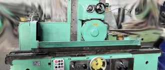
Information about the manufacturer of the 3G71M surface grinding machine
The manufacturer of the 3G71M surface grinding machine is Orsha Machine Tool Plant Krasny Borets , founded in 1900.
In 1959, the plant began production of high and especially high precision surface grinding machines.
In 1967, the 3711 surface grinding machine was released, the first metal-cutting machine of particularly high precision in the USSR.
Machine tools produced by the Orsha Machine Tool Plant
- 3B70V
- surface grinding machine with a horizontal spindle 160 x 400 - 3G71
- surface grinding machine with a horizontal spindle 200 x 630 - 3G71M
- surface grinding machine with a horizontal spindle 200 x 630 - 3D711VF11
- surface grinding machine with digital display, 200 x 630 - 3E710V
- surface grinding machine with a horizontal spindle 125 x 250 - 3E711V
- surface grinding machine with a horizontal spindle 200 x 630 - 3E711VF2
- CNC surface grinding machine, 200 x 630 - 3711, 3701
— especially high precision surface grinding machine 200 x 630, 125 x 400 - Orsha-F32SH
- wide-universal cantilever milling machine 320 x 1400 - TSH-1
- tabletop sharpening and grinding machine Ø 250 - TSh-2
– grinding and grinding machine Ø 300 - TSh-3
– grinding and grinding machine Ø 400 - TSh-4
– grinding and grinding machine Ø 400
Design and operation of the machine model 3G71M and its main components
Cross caliper
The cross support is a casting with mutually perpendicular guides: the lower ones are Y-shaped, the upper ones are flat and Y-shaped.
A hydraulic cylinder is installed between the upper guides, the rods of which are connected to the table.
To measure lateral movements, a bracket with an indicator is attached to the right wing of the caliper.
The cross feed nut bracket is attached to the lower plate of the caliper.
The left front fender has a built-in mechanism for longitudinal manual movement of the table.
Mechanism for longitudinal movement of the table
The mechanism is attached to the front left wing of the caliper, the table is moved manually by a flywheel through 4-5-1 gears. When you turn on the mechanical movement of the table, gear I must be disengaged from the table rack; to do this, you need to pull the flywheel and shaft toward you. Fixation is carried out with a spring-loaded ball.
For rigid fixation, there is a button 3, which directly presses ball 2 in the groove of the shaft. To block manual and hydraulic movement, a microswitch 6 is installed in the mechanism, which does not allow the hydraulic movement of the table to be activated until gear 1 is disengaged.
Feed mechanism
The mechanism provides:
- Automatic cross feed of the caliper
- Manual cross feed
- Accelerated movement of the caliper
- Automatic vertical feed of the grinding head for each longitudinal or transverse stroke of the table
- Manual vertical feed
- Faster movement of the grinding head
Automatic cross feed occurs at the moment of longitudinal table reverse due to the supply of a current pulse to an electric motor connected through gears to the cross feed screw. The feed amount is changed by turning the switches on the control panel. One makes a rough adjustment of the transverse feed, while the other makes a fine adjustment.
When working with automatic cross feed and with accelerated movement of the caliper, flywheel 3 must be disconnected from gear 5 using a button, and gear 5 must engage with gear 1.
For manual cross feed, gear 5 must be in mesh with gear 2.
Fine transverse feed is carried out through bevel gears 4 with a button located through the upper surface.
The accelerated movement of the cross support is activated by a toggle switch on the control panel.
Automatic vertical feed is carried out from a bladed hydraulic cylinder 14, operating at the moment of transverse or longitudinal reverse of the table, depending on the position of the toggle switch.
A lever with a pawl 15 is attached to the cylinder axis. The pawl can slide along the valve 13 or engage with the ratchet wheel 8. The ratchet wheel 8 is attached to gear 7, which, through gear 9, transmits movement to the worm shaft of the vertical feed reducer. The amount of automatic feed is regulated by a valve 13, which covers the teeth of the ratchet wheel 8.
On the button for rotating the shutter 6 there are divisions of the amount of feed to be set.
Manual vertical feed is carried out by a flywheel 10 through a pair of gears 12-9 and a gearbox.
Fine feed is carried out by a button through bevel gears 4.
For coarse manual feed, the fine feed button must be in the upper position, bevel gears 11 in this case are disengaged.
To prevent the flywheel from rotating during accelerated movement of the grinding head, the mechanism is equipped with a microswitch, which is pressed when the gears 12 and 9 are separated by the button located under the flywheel 10, and only in this position can the rapid movement motor be turned on.
Main technical characteristics of surface grinding machine 3g71m
Manufacturer: Orsha Machine Tool Plant Krasny Borets.
The main parameters of the machine are in accordance with GOST 13135. Surface grinding machines with a rectangular table. Basic dimensions. Accuracy standards.
- to GOST 8-71 - B. Roughness of machined surface V 10
- Dimensions of the desktop (length x width) - 630 x 200 , mm
- Limit dimensions of the processed surface (length x width x height) - 630 x 200 x 320 mm
- The largest mass of the workpiece is 150 kg
- Dimensions of a standard grinding wheel - Ø 250 x 32 x 76 mm
- Electric motor power - 2.2 kW
- Full machine weight - 2.25 t
Modern analogues of the 3G71M surface grinding machine
- 3D711VF11 - 600 x 200, manufacturer Orsha Machine Tool Plant Krasny Borets
- 3L741VF10 - 600 x 200, manufacturer Lipetsk Machine Tool Plant
Purpose and scope
Descriptions of the machine in question can be found quite often. It is used for grinding surfaces using the peripheral part of the wheel. It is possible to treat a surface that is located at right angles to the base. The characteristics can be significantly expanded if necessary.
The equipment in question allows for profile grinding. Technical characteristics determine that the method of threading the wheel profile affects the ability to process a particular shape, and also affects the accuracy of the resulting dimensions.
Often, the design of a surface grinding machine includes an electromagnetic plate, which is used to fasten the workpiece.
Key features that influence the scope of application are indicated in the data sheet. These include:
- The accuracy that can be achieved is class B.
- Roughness of the processed surface V 10.
Hydraulic diagram 3G71
The scope of application is very wide. You can often find it in large-scale production factories. The model is simple to operate; the control circuit allows precise control of the processing process.
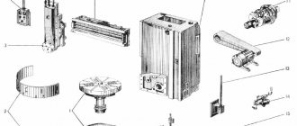
Location of components of the grinding machine 3G71M
Arrangement of components of the grinding machine 3g71m
List of components of the grinding machine 3G71M
- Machine cooling - 3G71M.60
- Machine bed - 3G71M.10
- Feed mechanism - 3G71M.22
- Hydrocommunications - 3G71M.70
- Longitudinal reverse mechanism - 3G71M.25
- Cross caliper - 3G71M.20
- Mechanism for longitudinal movement of the table - 3G71M.21
- Working table - 3G71.23E
- Grinding head - 3G71M.30
- Grinding wheel housing - 3G71M.34
- Column - 3G71M.11
- Hydraulic unit - 3G71M.71
- Grinding head lubrication unit - 3G71M.72
- Gearbox - 3G71M.33
- Electrical equipment - 3G71M.80
- Control station - 3G71M.81
- Power panel for electromagnetic plate - 3711.82
- Cross feed block - 3711.83
- Vertical feed panel - 3711.84
- Electrical cabinet - 3711.85
- Castle - 3711.87
- Braking unit for accelerated movement of the grinding head - 3711.88
- Transverse reverse mechanism - 3G71M.24
- Accessories - 3G71M.90
Device Features
The 3G71 spindle has a horizontal arrangement. This arrangement determines that the cross-type table support moves on the frame. The movement is carried out along the rolling guides. During operation, it is possible to move the workpiece in two mutually perpendicular directions.
Circuit diagram 3G71
In any passport you can find the features of the cross table:
- The instructions indicate that the mechanized feed from a hydraulic cylinder works.
- During operation, you can use a manual or mechanical feed mechanism.
- Longitudinal movement of the workpiece also allows you to speed up the work process.
- The longitudinal reverse of the table and the transverse reverse mechanism also significantly increase the functionality of the model.
There is a control panel. The back side of the frame has a column; a 3G71 spindle moves along vertical guides, which belong to the rolling category.
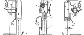
Location of controls for the 3G71M grinding machine
Location of controls for the grinding machine 3g71m
Location of controls for the grinding machine 3g71m
List of controls for the 3G71M grinding machine
- Fine Vertical Feed Button
- Manual vertical feed handle
- Limb for adjusting the vertical feed amount
- Manual cross feed handle
- Cross Feed Race Button
- Lubricate button for vertical feed screw and guides and cross feed screw
- Throttles for lubrication of table guides and cross support
- Throttles for adjusting the smoothness of table reverse
- Handle for starting, stopping and unloading the table
- Table speed control knob
- Handle for manual longitudinal table reverse
- Cooling valve handle
- Support for longitudinal table reverse
- Handle for manual longitudinal movement of the table
- Handle for manual transverse table reverse
- Button for fixing the mechanism for manual movement of the table
- Toggle switch “With stove - without stove”
- Toggle switch “Magnetic plate on”
- Button "Accelerated movement of the cross support"
- Regulator for coarse adjustment of cross feed amount
- Controller for fine-tuning the cross feed amount
- Toggle switch “Enable cross feed”
- Toggle switch “Enable vertical feed”
- Toggle switch “Vertical feed when reversing the table or cross support”
- Signal light "Machine on"
- Cooling On Switch
- All stop button
- "Sanding head down" button
- Grinding head up button
- Grinding wheel stop button
- Button "Start grinding wheel" and "Start lubrication"
- “Hydraulic Drive Drive” button
- Button "Start hydraulic drive"
- Warning light "No lubrication"
- Cross reverse stop
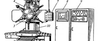
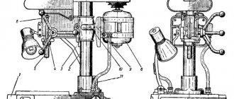
Main devices and movements
The diagram according to which the machine is assembled and its moves look like this. A column is attached to the frame. A cross support moves along the horizontal swing guides of the frame. The workbench also moves along with it, which performs longitudinal-translational moves backwards. The grinding head moves along the vertical guides of the column movement.
Rust remover for car body, bolts, pipes
On the inner lower side of the support on the GS 3e711v machine the following was fixed:
- cross feed reverse block;
- reverse block for longitudinal movement of the workbench;
- workbench longitudinal reverse block;
- workbench transverse reversal block;
- distribution panel;
- hydropanel.
The grinding spindle is assembled with preload, this is facilitated by high-precision radical-thrust bearings, which are lubricated with a “non-losing” lubricant. The hydraulic station on the RGS 3e711v is equipped with a volumetric control pump. Its scheme of action is to create a smooth regulation of the speed of movement of the workbench.
Installation drawing 3E711B
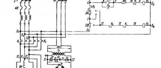
Kinematic diagram of the grinding machine 3G71M
The main movement is carried out from the electric motor El.I through a belt drive. The spindle receives a constant rotation speed.
The accelerated movement of the grinding head is carried out from the electric motor El.II through a cylindrical and worm gear. The worm gear is rigidly fixed to the hollow shaft III, inside which a nut is attached. When the gear with the nut rotates, the screw attached to the grinding head lowers or raises the grinding head.
When turning on the accelerated movement of the grinding head, the button should be in the “away” position, i.e. gear 17 must be disengaged.
To limit the upper position of the grinding head, a switch is installed inside the column.
Vertical automatic feed is carried out from a bladed hydraulic cylinder after each longitudinal or transverse stroke of the table.
Under the influence of oil pressure, the hydraulic cylinder rotor rotates with a lever with a pawl attached to it.
The pawl turns the ratchet 20, attached to the gear wheel 19, from the wheel the movement is transmitted through cylindrical wheels 17 and 18 to the worm, which rotates the nut 3. The limits of automatic vertical feed are 0.005-0.05 mm. Feed per tooth of the ratchet wheel is 0.00-5 mm. The amount of feed is regulated by turning the flap, which blocks part of the teeth of the ratchet wheel, i.e. part of its path, pawl 21 slides along the damper.
Precise manual cross feed is carried out from a button through bevel gears 14 15.
For one turn of the button, the caliper moves 0.4 mm.
Manual longitudinal movement of the table is carried out from the flywheel sitting on shaft X, through gears 10, I, 9, 7 and rack 8.
For one revolution of the flywheel, the table moves 18.1 mm.
In the normal position, gear 7 should be disengaged from engagement with the table rack. The flywheel must be in the “pull” position.
The mechanism has a lock that does not allow the mechanical movement of the table to be activated until the gear is disengaged. In the extended position, the microswitch is pressed, which allows the mechanical movement of the table to be activated in this position.
§6. PLANE GRINDING MACHINE 3E711V. Technical specifications.
Section: LIBRARY OF TECHNICAL LITERATURE Short path https://bibt.ru <<Previous page Table of contents of the book Next page>>
Surface grinding machines are classified: according to the location of the spindle - horizontal and vertical; according to the shape of the table - with a round and rectangular table. The main parameter characterizing surface grinding machines is the size of the table.
The 3E711B surface grinding machine with a rectangular table and a horizontal spindle is designed for processing flat surfaces of workpieces with the periphery of a wheel. Machine accuracy class B.
Technical characteristics of the machine 3E711B. Dimensions of the working surface of the table (length X width) 630×200 mm; speed limits for longitudinal movement of the table are 2-35 m/min; speed limits for transverse movement of the cross support 0.01-1.5 m/min; limits of vertical feed of the grinding head 0.001-0.09 mm; overall dimensions of the machine are 2700x1775x1910 mm.
Basic mechanisms and movements in the 3E711B surface grinding machine. Column B is attached to frame A (Fig. 125). Along the horizontal rolling guides of the frame, a cross support B with table D moves in the transverse direction, performing a longitudinal reciprocating movement. The grinding head G moves along the vertical rolling guides of column B. The frame contains mechanisms E and G for vertical and transverse feed, as well as the hydraulic drive of the machine.
Rice. 125. Kinematic diagram of the 3E711B surface grinding machine
Kinematics of the 3E711V machine. The grinding wheel receives its main movement from the electric motor M1 (N = 5.5 kW, n = 1500 min-1) through a poly-V-belt drive. Spindle II is mounted in multi-wedge bearings with self-aligning liners.
The transverse feed of the 3E711B cross support is carried out from the M2 DC motor (N = 0.25 kW, n = 30-3000 min-1) through helical wheels z = 34-100, z = 60-100 and lead screw VII.
When the M1 clutch is engaged in the wheel z = 100, automatic feeding occurs - continuous or intermittent for each table stroke (or double table stroke). To obtain intermittent feed when the table is longitudinally reversed, the M2 motor is given a command to turn on from a contactless travel switch.
Manual coarse and fine transverse feeds are carried out when the M1 clutch is turned to the left. A fine manual feed is obtained by rotating dial 2 through a worm pair z = 1-100; rough manual feed is carried out by handwheel 4 (the worm z = 1 is disengaged by handle 3).
The longitudinal feed of the table comes from a hydraulic drive; speeds are infinitely adjustable. Manual longitudinal feed is carried out by handwheel 1 with a built-in planetary mechanism. Satellites z = 18 and z = 19 roll around a stationary central wheel z = 19 and through another central wheel z = 20 the rotation is transmitted to the rack wheel z = 18 and the rack. The planetary gear significantly reduces the amount of movement per one revolution of the dial.
The vertical feed of the 3E711B grinding head is carried out from the M3 stepper motor at the moment of reversing the table or cross support. Rotation is transmitted to the lead screw XII with the M2 clutch engaged to the right through the wheels z = 34-100-100, the cardan shaft X, the engaged electromagnetic clutch M3 and the worm pair z = 1-30. Manual (coarse and fine) vertical feeds are carried out similarly to transverse manual feeds using handwheel 6 along dial 5.
The fast installation movements of the grinding head of the 3E711B surface grinding machine occur from the M4 asynchronous electric motor (N = 0.4 kW, n = 1500 min-1) with the M3 coupling disconnected.
Skip to navigation
Power supply system for electrical equipment of the 3G71M machine
The machine is connected to a three-phase alternating current network with a voltage of ~380 V, a frequency of 50 Hz.
- Asynchronous squirrel-cage electric motors M1-M3, M5, M6, M8 and transformer TP3 are supplied with a voltage of 380 V alternating three-phase current.
- The electric motor M7 is supplied with a voltage of ~220 V alternating three-phase current, taken from the transformer Tr3.
- The control circuit and electromagnet EM1 are supplied with a voltage of ~110 V AC from transformer Tr2.
- The local lighting bracket LI is supplied with ~24 V AC voltage from transformer Tr2.
- The signaling equipment L2 and L3 is supplied with a voltage of ~5 V AC from the transformer Tpl.
- The electromagnetic device is supplied with 110 V DC voltage through the rectifier D11. The DC control circuits operate from the voltage taken from the D10 rectifier, the input of which is supplied with a 36 V AC voltage from the Tpl transformer.
- The contactless limit switch VB2 is powered by a constant voltage taken from the rectifier D26, the input of which is supplied with a voltage of 31 V from the windings of the 36 V and 5 V transformer Tpl, connected in opposite directions.
Operation of the hydraulic drive and interaction of components of the 3G71M grinding machine
The hydraulic drive of the machine is put into operation by pressing the “Start hydraulic drive” button, followed by setting the hydraulic panel valve 17 to the “Start” position. The oil flow, pumped by the vane pump 2, through the filter 4 through the pipeline 12 enters the central bore of the reversible spool 25 of the panel 17. When the spool 25 is positioned as shown in the diagram, the main flow enters the left bore and through the pipeline 18 into the hydraulic cylinder 20 of the table movement. The table moves in the direction of the arrow. Draining from hydraulic cylinder 20 occurs through pipeline 21 through throttle 14, valve II into hydraulic tank I.
The speed of movement of the table is regulated by throttle 14. The table moves to the right until the stop 19 associated with the table throws the reverse lever 23, which, through a system of levers, switches the control spool 24 to the left position. In this case, the right end chamber of the reverse spool is connected to pressure, spool 25 moves to the left, as a result of which the table reverses. Pipeline 21 becomes pressure, pipeline 18 becomes drain. The table moves in the opposite direction until the stop 22 moves the lever 23 to the reverse position.
The cycle is then repeated as described above.
Automatic vertical feed is carried out by turning on the electromagnet of the reversing spool 28.
The oil flow through pipeline 12 through the reversing spool and pipeline 27 enters the lower cavity of the torque hydraulic cylinder, from the upper cavity the oil through pipeline 26 through the spool and pipeline 29 is drained into the hydraulic tank. The flag is rotated clockwise. Through a gear system, rotation is transmitted to the vertical feed screw. The grinding head is fed vertically.
When the electromagnet is turned off, pipeline 26 becomes pressure, pipeline 27 becomes drain. The checkbox returns to its original position
Lubrication of the table guides and cross support, the vertical feed screw and guides and the cross feed screw is carried out from pipeline 13 through filter 10 and pipeline 15.
The oil consumption for lubrication of the table guides and cross support is regulated by throttle 16.
The oil supply for lubrication of the vertical feed screw and guides and the cross feed screw is turned on periodically by pressing button 9.
Excess oil coming from the table guides and cross support is drained through pipelines 7 and 8 into the hydraulic tank.
Design features of the machine
The main purpose of the 3G71 machine is grinding various parts and workpieces using special abrasive wheels. The process occurs with a spindle on which the abrasive is located. Changing the position of the part can occur due to the displacement of the work table and spindle head.
Basically, machining is carried out by contacting the periphery of the wheel with the workpiece being processed. With the help of special devices it is possible to change the angle up to 90°. However, to do this, you must purchase components that are not included in the standard equipment package.
The design and operational characteristics of the machine include the following:
- the electromagnetic plate ensures a stable position of the workpiece during processing;
- independent mechanisms for moving the work table and grinding head. The kinematic diagram of the latter is based on rolling guides;
- convenient location of feed response devices. They are located at the bottom of the worktable support. The control unit for the coolant supply system is also located there.
The control components are located in a separate block, which is installed on the right side of the equipment. During operation of the 3G71 machine, access to it remains free, regardless of the operating mode and position of the work table.
When installing additional components, it will be possible to perform profile grinding of workpieces. However, before this, it is necessary to agree on the dimensions and mounting locations of the device.
Technical data and characteristics of the 3G71M machine
| Parameter name | 3G71 | 3G71M |
| Main settings | ||
| Accuracy class according to GOST 8-82 | IN | IN |
| The largest dimensions of processed products (length x width x height), mm | 630 x 200 x 320 | 630 x 200 x 320 |
| Distance from the spindle axis to the table mirror, mm | 80…445 | 80…445 |
| Maximum mass of the processed product, kg | 100 | 150 |
| Machine work table | ||
| Dimensions of the working surface of the table (length x width), mm | 630 x 200 | 630 x 200 |
| Longitudinal movement of the table, mm | 710 | 700 |
| Transverse movement of the table, mm | 235 | 245 |
| Speed of longitudinal movement of the table, m/min | 5…20 | 3…25 |
| Table movement per revolution of the flywheel of the longitudinal movement mechanism, mm | 15,3 | 18,1 |
| Table cross feed mechanism | ||
| Price for dividing the flywheel dial for transverse movement of the table, mm | 0,05 | 0,02 |
| Caliper movement per flywheel revolution, mm | 6 | 2,0 |
| Price for dividing the micrometric feed dial for transverse movement of the table, mm | 0,01 | 0,005 |
| Automatic cross feed for each table stroke, mm | 0,2…4,0 | 0,3…10 |
| Automatic continuous feed, m/min | 0,7 | |
| Grinding head | ||
| Maximum vertical movement of the grinding head, mm | 365 | |
| Speed of accelerated vertical movement of the grinding head, m/min | 0,27 | 0,28 |
| Grinding wheel dimensions, mm | 250 x 32 x 76 | 250 x 32 x 76 |
| Grinding speed, rpm | 2680 | 2680 |
| Dividing value of the vertical movement flywheel dial, mm | 0,001 | 0,002 |
| Automatic feed of vertical movement (stepped in increments of 0.005), mm | 0,005…0,05 | 0,002…0,05 |
| Displacement of the grinding head per revolution of the flywheel, mm | 0,125 | |
| Electrical equipment and machine drive | ||
| Number of electric motors on the machine | 5 | 5 |
| Spindle drive electric motor, kW | 2,2 | 2,2 |
| Hydraulic drive electric motor, kW | 1,1 | 1,1 |
| Electric motor for accelerated movement of the grinding head, kW | 0,18 | 0,4 |
| Cooling pump electric motor, kW | 0,125 | 0,125 |
| Magnetic separator electric motor, kW | 0,08 | 0,08 |
| Total installed power of all electric motors, kW | 3,685 | 4,355 |
| type of supply current | 50Hz, 380/220V | 50Hz, 380/220V |
| Dimensions and weight of the machine | ||
| Machine dimensions (length x width x height), mm | 1870 x 1550 x 1980 | 1980 x 1840 x 1860 |
| Machine weight, kg | 2000 | 2250 |
- Universal high-precision surface grinding machine with a horizontal spindle and a rectangular table. Model 3G71M. Operating manual 3G71M.00.000 RE, 1978
- Alperovich T.A., Konstantinov K.N., Shapiro A.Ya. Design of grinding machines, 1989
- Alperovich T.A., Konstantinov K.N., Shapiro A.Ya. Setup and operation of grinding machines, 1989
- Dibner L.G., Tsofin E.E. Sharpening machines and semi-automatic machines, 1978
- Genis B.M., Doctor L.Sh., Tergan V.S. Grinding on cylindrical grinding machines, 1965
- Kashchuk V.A., Vereshchagin A.B. Grinder's Handbook, 1988
- Kulikov S.I. Honing, 1973
- Lisova A.I. Design, adjustment and operation of metal-cutting machines, 1971
- Loskutov V.V. Metal grinding, 1985
- Loskutov V.V. Grinding machines, 1988
- Lurie G.B. Grinding machines and their adjustment, 1972
- Lurie G.B. Design of grinding machines, 1983
- Menitsky I.D. Universal sharpening machines, 1968
- Mutsyanko V.I. Bratchikov A.Ya. Centerless grinding, 1986
- Naerman M.S., Naerman Ya.M. Guide for training grinders. Textbook for vocational schools, 1989
- Popov S.A. Grinding work, 1987
- Tergan V.S. Grinding on cylindrical grinding machines, 1972
- Shamov B.P. Types and designs of main components of grinding machines, 1965
Bibliography:
Related Links. Additional Information
- Classification and main characteristics of the grinding group
- Repair, restoration and modernization of grinding machines: the American approach
- Cylindrical grinding. Processing on cylindrical grinding machines. Grinding Methods
- Setting up a cylindrical grinding machine when installing parts in centers
- CNC grinding machines
- Marking of grinding wheels
- Testing and checking metal-cutting machines for accuracy
- Grinding machines. Market of grinding machines in Russia
- Manufacturers of sharpening and grinding machines in Russia
- Directory of grinding machines
- Manufacturers of metal-cutting machines
Home About the company News Articles Price list Contacts Reference information Interesting video KPO woodworking machines Manufacturers
Spindle head
- The greatest vertical movement: for the 3G71 machine is 365 mm. The 3D711VF11 machine has a little more: 400 mm. The G-CS3060AH and G-CS3060AH machines are significantly larger - 600 mm and 550 mm, respectively. This makes it possible to use large and small grinding wheels.
- Grinding wheel dimensions: the standard wheel for 3G71 is a wheel of 250x32x76 mm. The 3D711VF11 machine uses a grinding wheel with an increased diameter. In addition, the diameter of the machine spindle is also larger. Size of circle used: 300×40×76 mm. On KAMIOKA G-CS3060AH it is possible to use a circle not only with a larger diameter, but also with a greater height. In addition, the machine spindle is also larger. Circle size: 355×50×127 mm. On the L&W G-CS3060AH machines, due to the variable spindle diameter, wheels of different sizes can be used. Small circle: 180×13×32 mm. Large circle: 350×38×127 mm.
- Rotation speed: 2,680 rpm for 3G71. Slightly less for 3D711VF11 - 2,230 rpm. The G-CS3060AH and G-3A3060 we recommend are even lower - 1,750 and 1,500 rpm. The question may arise as to why the rotation speed is lower, because the quality of processing depends on the rotation speed. This is true, but at the same time the bearings wear out faster and vibration increases. By using a massive bed, reinforced guides, vibration-damping racks and a special spindle design, Taiwanese manufacturers were able to increase the processing quality to level C, while increasing the wear resistance of their machines.