Information about the manufacturer of the rotary lathe 1512
The developer and manufacturer of the 1512 rotary lathe is the Krasnodar machine-tool plant Sedina , founded in 1911.
In 1915, the first lathe was produced. In 1922, the enterprise received its modern name - in honor of turner G. M. Sedin.
In 1935, the first rotary lathe, model 152, was produced, and by 1937, the priority profile of the plant was determined - machine tool building, and first of all, the production of rotary lathes.
Vertical turning machines produced by the Krasnodar Machine Tool Plant, KSZS
- 1А512МФ3
single-column vertical turning machine with CNC Ø 1250 x 1000 - 1А516МФ3
single-column vertical turning machine with CNC Ø 1600 x 1000 - 1L532
- two-column rotary lathe Ø 3150 x 1600 - 1M557
- two-column rotary lathe Ø 3200 x 1600 - 1286-6
six-spindle vertical lathe Ø 630 x 750 - 1508
— single-column rotary lathe Ø 800 x 800 - 1510
— single-column rotary lathe Ø 1000 x 800 - 1512
— single-column rotary lathe Ø 1250 x 1000 - 1512F3
single-column vertical turning machine with CNC Ø 1250 x 1000 - 1516
— single-column rotary lathe Ø 1600 x 1000 - 1516F1
- single-column rotary lathe with digital indicator Ø 1600 x 1000 - 1516F3
- single-column vertical turning lathe with CNC Ø 1600 x 1000 - 1525
— two-column rotary lathe Ø 2500 x 1600 - 1531M
single-column rotary lathe Ø 1250 x 1000 - 1541
— single-column rotary lathe Ø 1600 x 1000 - 1553
two-column rotary lathe Ø 2300 x 1600
Single-column turning lathe 1512. Purpose and scope
The single-column rotary lathe model 1512 is a universal machine and is designed for processing a variety of products made of ferrous and non-ferrous metals in small-scale and mass production.
Model 1512 is the most common among rotary lathes in the former USSR. The machine allows turning parts with a diameter of up to 1250 mm, a height of up to 1 meter and a weight of up to 3200 kg . The machine was exported to many countries around the world.
The design of the 1512 is unified with the design of the 1516 machine and differs only in the dimensions of the faceplate and the power of the electric motor.
The machine can perform cylindrical and conical turning and boring, turning of planes - both internal and external, drilling, countersinking and reaming of central holes, as well as semi-finishing and finishing turning of flat end surfaces.
The machine has two supports :
- vertical with a five-position turret with automatic rotation and locking at each position
- horizontal (side) with four-position tool holder
The technological capabilities of the machine are significantly expanded with the help of a self-centering faceplate supplied upon special order, devices (for thread cutting, processing of conical surfaces, turning shaped surfaces of bodies of revolution along a copier, processing parts on stops) and a device for processing with cooling.
The following operations can be performed on the machines:
- turning cylindrical and conical surfaces;
- boring of cylindrical and conical surfaces;
- turning flat end surfaces using vertical and lateral supports.
In addition, a vertical support can be used to grind flat end surfaces while maintaining a stepwise constant cutting speed in finishing and semi-finishing modes; drilling, countersinking and reaming; Grooving and parting.
When using special devices and devices that are supplied with the machines upon special order for an additional fee, the machines can produce:
- processing of parts according to specified dimensions (on stops);
- cutting threads, turning and boring conical surfaces;
- processing of shaped surfaces of bodies of rotation using a copier (electrocopier);
- processing of parts with cooling.
In the usual version, the machines are supplied with a vertical turret support, which has a mechanical rotation and clamping of the turret head, and a side support.
In addition, upon special order, for an additional fee, a machine with a self-centering faceplate with manual clamping of the product can be supplied.
All accessories can be mounted on the machine at the same time, with the exception of cooling, which cannot be installed simultaneously with the self-centering faceplate.
Due to the fact that the installation of fixtures requires significant changes and modifications to the machine, orders for the manufacture of fixtures for previously supplied machines cannot be fulfilled. Accessories are supplied only with the machine.
The significant power of the main drive electric motor, the high rigidity of the base parts and the sufficient strength of all elements of the kinematic chain, combined with wide ranges of control of the faceplate speeds and feed rates, allow the machines to perform highly productive work at high-speed cutting conditions.
Main technical characteristics of screw-cutting lathe 1512
Manufacturer: Krasnodar Machine Tool Plant named after Sedin.
The main parameters of the machine are in accordance with GOST 44-93. Rotary lathes. Basic parameters and dimensions. Standards of accuracy and rigidity.
- Machine accuracy class N according to GOST 8-77.
- The largest diameter of the workpiece being processed is Ø 1250 mm
- The highest height of the processed workpiece is Ø 1000 mm
- Faceplate diameter - Ø 1120 mm
- The largest weight of the processed workpiece is 3200 kg
- Faceplate rotation speed - 5..250 rpm, 18 steps
- Electric motor power - 30 kW
- Full weight of the machine - 16.5 tons
Modifications of the rotary-turning machine, single-column 1512
1512.000, 1512-1, 1512-2, 1512.300, 1512.400 - universal single-column turning-boring machine
1512F1, 1512PF1, 1512F1.041, 1512F1.300, 1512F1.323, 1512F1.4 00, 1512F1.423 - rotary lathe with digital display — digital display device
1512F2, 1512F3, 1512F3.271, 1512F3.471, 1512MF4 - rotary lathe with CNC - numerical control device
Purpose and layout
According to the domestic classifier, designation 1512 is deciphered as follows:
1 — equipment group (lathe);
5 — type (carousel);
12 - dimensional characteristics (maximum processing diameter - 1250 mm).
Why is the installation called a carousel? The meaning of the term is that the faceplate with clamping elements, when rotated around a vertical axis, resembles a well-known attraction. A competitor to the rotary lathe is the lobe lathe, which has a traditional horizontal spindle arrangement. Both are designed for turning short parts, but the machine in question has a number of advantages:
- possibility of longer processing (height to diameter ratio up to 1);
- unloading the spindle from bending forces;
- ease of loading workpieces;
- significantly better fixation.
Disadvantages include difficult chip removal and inconvenience of diametric measurements.
Technological capabilities
The purpose of carousel-type machines is to process relatively flat parts of a circular configuration (disks, flanges, covers, flywheels, wheels, gears, etc.). Using standard tools (various types of cutters, cutting heads, drills, countersinks, reamers), the following basic technological operations are performed:
- external turning of cylindrical and conical parts;
- grinding of ends and ledges;
- cutting circular grooves;
- boring through and stepped holes;
- processing of holes with a rod tool.
Using special devices, it becomes possible to expand the range of operations performed:
- processing of spherical and other nonlinear surfaces;
- deep drilling;
- thread cutting;
- grinding and superfinishing;
- Roller rolling and lapping.
The workpiece is secured to the faceplate using adjustable clamps and cams, and small-diameter parts are secured in an additional self-centering chuck.
Key figures
Table 1 shows the most important information characterizing the machine system. Complete information is contained in the equipment operating manual (passport) published by the Krasnodar Machine Tool Plant.
Table 1. Model 1512 Specifications
| Those. characteristics | Meaning | |
| The largest parameters of the installed workpiece | Diameter, mm | 1250 |
| Height, mm | 1000 | |
| Weight, kg | 4000 | |
| Platform diameter, mm | 1120 | |
| Angular speed of the faceplate, rpm (18 speeds) | 5 — 250 | |
| Tool feed amount, mm/rev (18 steps) | 0,03 — 12,5 | |
| Speed of installation movements, mm/min (18 values) | 5 — 1800 | |
| The greatest angle of inclination of the turret caliper | ±45° | |
| Main movement power, kW | 30 | |
| Installation weight, t | 16,5 |
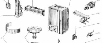
Location of machine components 1512
Location of machine components 1512
List of components of the machine 1512
- Table – 30
- Faceplate guard - 31
- Vertical support - 650
- Control pendant - 990
- Control panel suspension - 99
- Crossbar - 50
- Cross member movement mechanism - 57
- Bed - 10
- Mechanism for manual movement of vertical support - 420
- Vertical support feed box - 40
- Gearbox - 21
- Casing - 25
- Mechanism for transmitting movement to feed - 15
- Lubrication - 34
- Horizontal caliper (side) - 66
- Feed box horizontal caliper (side) - 46
A distinctive feature of the design of the machines is that most assembly units are made as independent products, which facilitates assembly not only during the manufacturing process, but also during repairs.
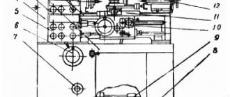
Location of controls for rotary lathe 1512
Location of controls for rotary lathe 1512
List of machine controls 1512
- Handle for fastening the cutting head of the side support
- Screw for fixing the cutting tool arbor in the turret socket
- Vertical support slider fixing screw
- Nuts for fastening the rotary slide of the vertical support
- Handle for connecting the machine to the electrical network
- Crossbar clamp handle
- Buttons for moving the crossbar “up”, “down”
- Square worm for rotating the vertical slide slide
- Vertical support fixing screw
- Flywheel for manual vertical movement of the vertical support slider
- Flywheel for manual horizontal movement of vertical caliper
- Control pendant
- Side caliper slider fixing screw
- Side support fixing screw
- Flywheel for manual horizontal movement of the side slider
- Flywheel for manual vertical movement of the side support
Control panel for rotary lathe 1512
Control panel for rotary lathe 1512
List of controls on the machine control panel 1512
- "GENERAL STOP" button
- “NO LUBRICATION” warning light in the main drive
- Main drive STOP button
- Main drive START button
- Switch for turning on and off the vertical support brake
- Turret rotation and clamp button
- Switch for setting working feeds and installation movements of the vertical support
- Vertical support feed switch
- Switch for the direction of movement of the vertical support
- Signal light “VERTICAL CALIPER IN OPERATION”
- Light switch on/off
- Signal light “SIDE CALIPER IN OPERATION”
- Side support movement switch
- Side support feed switch
- Switch for setting working feeds and installation movements of the side support
- Switch for turning on and off the brake of side caliper movements
- Switch for faceplate revolutions per minute
- Switch for switching on and off step-constant cutting speed
- Faceplate START button
- Faceplate "STOP" button
- Switch for turning on and off the faceplate jog start
Specifications
Considering the technical characteristics, we will also pay attention to deciphering the name of the machine 1512, which was given in accordance with previously introduced standards: the first digit indicates membership in the turning group, the second in the rotary-turning subgroup, the next two - the maximum size of the workpieces installed. The main technical characteristics are as follows:
- The maximum height of the cutting tool above the table is 1,000 mm.
- The workpiece weight limit is 5,000 kg.
- The installed faceplate can rotate at a frequency from 1 to 250 rpm. At the same time, the manufacturer included in the passport information about the presence of two rotation speed shift gears. The adjustment is stepless.
- The electrical circuit provides for the installation of a main electric motor, which has an impressive power of 55 kW. This information determines that the 1512 rotary lathe is placing a significant load on the facility's power supply.
- The traverse can move in the vertical direction over a distance of 660 mm. Movement is limited by mechanical stops.
- The machine layout also determines the presence of a support, which can move horizontally by 775 mm and vertically by 700 mm.
- When choosing a cutting mode, you should pay attention to the fact that the maximum permissible force at the time of processing is 35 kN.
- There is a mechanism for rotating the slider at an angle of no more than 45 degrees.
- The installed turret has 5 positions. It is mounted on a cylindrical bushing. The master changes the cutting tool by pressing the corresponding key on the control panel. Rotation is transmitted from an electric motor through gears.
- The main support can move vertically by 1,000 mm, horizontally by 630 mm, the maximum cutting force is 25 kN. The position of this element can be set at a speed of 2,000 mm/min. The passport also contains information that this caliper has 18 feeds.
Download the passport (operating instructions) of the rotary lathe 1512
When choosing this model, it is worth considering that its weight is 14,800 kg. This point determines the presentation of special requirements for the base on which the equipment will be installed. The electrical circuit of the equipment determines its connection to a three-phase network with a voltage of 380V.
Kinematic diagram of machine 1512
Kinematic diagram of rotary lathe 1512
The kinematic diagrams of machines 1512 and 1516 are similar to each other and differ from each other only in the kinematics of the chain of the feed motion transmission mechanism and the number of teeth of the table gears.
Due to the different number of teeth on the table gears, machines 1512 and 1516 have different speed limits for the faceplate speeds with the same gearbox.
The kinematics of the chains of the feed motion transmission mechanism are different for the machines, but their gear ratios are selected in such a way that the total gear ratio of the kinematic chain from the faceplate to the feed box is the same for both machines. This allows you to use the same feed boxes and obtain the same feed amounts.
Machine feed box
Feed box of machine 1512
Considering the main parameters of the feedbox, we note the following points:
- It is located on the right at the end of the cross member. The side caliper with the feed box is mounted directly on the body.
- All structural elements are hidden in a body made of cast iron. The casting has a box-shaped shape and additional stiffening ribs, which determines the high rigidity of the structure.
- Torque is transmitted from a vertically located splined shaft, which is connected to the operation of the gearbox.
The gears installed during operation of the rotary lathe do not disengage when changing gears.
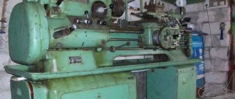
Appearance of machine 1512
Design of the main components of the rotary lathe 1512
Gearbox of machine 1512
The gearbox is used to ensure rotation of the faceplate, as well as starting, stopping and changing speeds. Rotation is transmitted to the input shaft of the gearbox from the main drive electric motor through a V-belt drive. The gearbox provides the faceplate with 18 speed levels.
The gearbox is controlled remotely from a pendant remote control.
The presence of electromagnetic clutches in the gearbox allows you to switch speeds on the go and thereby ensure the maintenance of a stepwise constant cutting speed when processing end surfaces.
The gearbox has six shafts mounted on rolling bearings in a housing with a parting plane along the shaft axes for ease of assembly.
At higher speeds, the start is carried out in stages in two, three or four stages. The number of acceleration stages increases with increasing speed of the faceplate.
Switching of clutches during stepwise acceleration is carried out automatically (for a detailed description, see Part 2 of the Operating Manual 'Electrical equipment of machine tools').
Changing the speed from 1st to 12th stage is carried out by turning on the corresponding combinations of electromagnetic clutches.
To enable the jog mode of operation of the faceplate, which is used when installing and aligning the part, it is necessary to place the switch on the pendant control panel in the “Jog start” position of the faceplate and press the “Start” button of the faceplate.
There are no special braking devices in the gearbox, and the faceplate is braked by simultaneous activation of three electromagnetic clutches.
Machine table
There are no fundamental design differences between the tables of machines 1516 and 1512. The machine parts are similar and differ from each other only in size.
The table consists of a body with circular guides, a faceplate with a spindle and a faceplate drive.
The table body is a cast iron with a developed system of ribs, giving it greater rigidity.
At the top of the table body there are annular projections that fit into the annular grooves of the faceplate, forming a labyrinth. This prevents lubricant from splashing and protects against chips, cast iron dust, emulsion and other contaminants getting inside the table.
The faceplate is driven from the gearbox through a pair of bevel gears with a circular tooth, then through a cylindrical helical pair: a gear and a ring gear rigidly connected to the faceplate.
Machine feed boxes
The design of the feed boxes of the lateral and vertical supports is the same.
The vertical support feed box is mounted on the right end of the cross member; side caliper feed box - directly to its body.
The feed box body is a box-shaped cast iron with sufficient rigidity. All feed box shafts are mounted on rolling bearings.
The feed boxes are driven from a vertical splined shaft, which receives rotation from the output shaft of the gearbox through the mechanism for transmitting movement to the feed (see Fig. 6).
The feed boxes provide the calipers with 18 working feeds and 18 speeds of installation movements. This is achieved by switching on the appropriate combinations of electromagnetic clutches of the feed boxes (for the switching diagram of electromagnetic clutches, see Part 2 of the Operating Manual 'Electrical equipment of machine tools*).
All gears of the feed boxes are in constant engagement.
A turret head with five slots and holes for attaching a tool is mounted on a cylindrical bushing. Changing the positions of the turret is carried out remotely from a pendant control panel. By pressing the “Turret Head” button, the electric motor for turning the turret head, mounted on the upper end of the slide, is turned on. Rotation from the electric motor is transmitted through gears to the drive shaft.
The main movement (rotation of the faceplate) is transmitted from the electric motor 1 through the V-belt transmission 2 - 3 to shaft I, then through the gearbox, shaft V, bevel gears 25 - 26 and wheels 27-28 is transmitted to the faceplate. The gearbox is equipped with eight electromagnetic clutches, the switching of which allows you to provide the faceplate with 18 rotation speeds ranging from 5 to 250 rpm.
The feeds of the calipers (revolving and side) are borrowed from the faceplate through two independent feed boxes with the same kinematics. Each box is equipped with eight electromagnetic clutches, switching which makes it possible to obtain 16 feed rates for both calipers.
Horizontal feed of turret support . From shaft VIII of the faceplate through gear 28 - 27, bevel gears 26 - 25, 24 - 23, gear 29 - 30 and bevel pairs of wheels 31 and 53, the movement is transmitted to shaft XII of the feed box (shown separately at the top left). From the feed box, the shaft XX of the caliper mechanism receives rotation, and then through gears 52 and a screw pair 65, the turret caliper receives horizontal feed.
Vertical feed of the turret support . From shaft VIII of the faceplate to shaft XXI of the feed box, rotation is carried out along the same chain; Then, through bevel gears 55 - 56, a cylindrical pair of wheels 57, a conical pair 58 and a screw pair 59, the turret caliper receives the feed movement.
Horizontal feed of side support . As before, the movement goes from shaft VIII of the faceplate to shaft XII of the feed box, then through the feed box to shaft XX and then through gears 39 - 41 and screw pair 42, the side caliper receives feed.
Vertical feed of side support . From the faceplate shaft to the feed box shaft XII, the movement proceeds along the same chain, then through the feed box the shaft XXI of the caliper mechanism receives rotation and through the bevel gears 35-36 and the screw pair 43 the side caliper receives feed.
Both supports receive accelerated movement
Description of the hydraulic circuit of the model 1541 rotary machine
Control of the main drive of the machine. When the faceplate rotation speed selection handle is set to the position corresponding to the required rotation speed, a switching circuit for the electromagnets of distributors 6, 7, 8, 9, 10 is prepared. Pump 3, through filter 1 and check valve 2, sucks oil from the hydraulic tank and through plate filter 4 along the line 29 supplies it to the distributor 26, which is turned off at this time. Then the oil along line 35 through the needle throttle 24 enters under the locking piston of the cylinder 22 for fixing the position of the gears and lifts the locking piston up, thereby releasing the gear shift rods of the gearbox. Having risen upward, the locking piston allows oil access to the oil distributor and from it into the cavities of the gear shift cylinders corresponding to the selected rotation speed. Distributor electromagnets 6, 1, 8, 9, 10 are switched on.
When you press the “Start faceplate” button, the distributor electromagnet 26 is turned on and the oil enters the clutch engagement cylinder 13. The cylinder rod begins to move to the right until the drain hole opens. The clutch forks must be adjusted so that in this position the clutch begins to work with slipping, rotating the gearbox gears at a “creeping speed”. At the same time, oil enters cylinder 23 under the piston, which rotates the gearbox gears through a rack to facilitate shifting.
When switching to the start position of the distributor 26, line 35 is switched on to drain. No longer held in the upper position by oil pressure, the piston-retainer of cylinder 22 tends to fall down under the action of a spring. To prevent the gears from becoming tooth-to-tooth, switching is performed at the “creeping speed” of the clutch.
Having descended, the piston-clamp of the cylinder 22 for fixing the position of the gears closes the drain hole of line 32, and the starting clutch is fully engaged. At the same time, line 34 is closed and the pressure is removed from cylinders 15, 16, 17, 18, 19, 20, 21, 25, and line 35 is turned on to drain and the spring returns the piston of cylinder 23 to its original position.
When you press the “Stop faceplate” handle, the electromagnet of the distributor 26 is turned off and its spool is moved by a spring to the upper position. Oil is supplied to brake cylinder 14 and the faceplate stops.
Throttle 12 is used to adjust the activation time of the working clutch and brake. Instant activation of the working clutch or brake when switching the faceplate rotation speed can lead to an accident.
Throttle 24 is used to adjust the lowering time of the latch. When lowered quickly, the lock will lock the triple gear unit in the middle position, preventing it from moving from one extreme position to another. In this case, the rotation speed of the faceplate will not correspond to the selected one, and when braking, when the latch rises, the triple block switching will continue. To prevent this phenomenon, the system is equipped with a locking mechanism with a microswitch, which eliminates the possibility of turning on the distributor 26 if the position of the triple gear block does not correspond to the position of the rotation speed selection handle.
The hydraulic system of the machine provides for the possibility of abruptly starting and stopping the faceplate when using its two lowest rotation speeds, which is carried out using distributor 11. This distributor is turned on when using all faceplate rotation speeds except the two lowest indicated. When you set one of the two lowest rotation speeds with the rotation speed selection handle and turn on the “Start” button of the faceplate again, the distributor 11 is turned off, and the oil passes both through the throttle 12 and through the grooves of the valve spool 11, which ensures a quick supply of oil to the operating cylinder 13 clutch When the faceplate is turned off, the oil is also drained through distributor 11, which ensures an abrupt stop of the faceplate.
The cross member is released as follows: oil is supplied by pump 3 through line 29 to the distributor 6. When one of the cross member movement buttons is pressed, the distributor 6 is turned on, and oil through line 31 enters the cross member clamp cylinder 5 and releases the cross member clamping arms; then the limit switch 5VK turns on the motor for moving the crossbar and its movement begins. At the end of the movement, the engine turns off and, at the same time, the distributor turns off, stopping oil access to cylinder 5 and connecting cylinder 5 to drain line 30. Under the action of a spring, the cylinder returns to its original position.
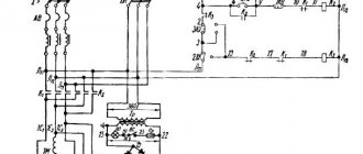
Characteristics of the electrical equipment of the machine 1512
Electrical circuit of the power supply of the machine 1512
Electrical circuit of the power supply of the rotary lathe 1512
The electrical equipment of machine tools consists of electric motors, electrical controls, limit switches to limit the movement of moving parts of the machine and control equipment.
The machines are equipped with five three-phase asynchronous electric motors with a squirrel-cage rotor:
- main drive motor 1M1;
- oil pump drive motor 1M2;
- cross member movement motor 1M3;
- motor for installation movements of the upper support, installation movements of the side support 4M1 and three single-phase asynchronous capacitor electric motors with a squirrel-cage rotor to drive the lubricator of the lubrication system;
- cross member motor 1M4;
- upper support motor 2M2 and 2M3
The following voltage values are accepted on the machine
- 380V three-phase alternating current, frequency 50 Hz - power supply of power circuits;
- 110V single-phase alternating current - power supply to coils of magnetic starters and single-phase electric motors;
- 36V single-phase alternating current - power supply for the circuit for selecting the direction of travel of the stepper finder;
- 24V - DC power supply for local lighting lamps;
- 24V - DC power supply for control circuits and electromagnetic couplings;
- 90V - DC power supply to the stepper finder coils.
All electrical equipment for controlling the machine is located in the niche of the machine. The machine is controlled from a pendant control panel.
The electrical equipment of the machine performs the following functions:
- Faceplate control:
- start-up in operating mode;
- start in jog mode;
- step change in speed with a rotating faceplate;
- maintaining a stepwise constant cutting speed when turning end surfaces with the upper support (changing the speed of rotation of the faceplate using a cam rack and a limit switch);
- faceplate stop.
Caliper control:
- working feeds (feed selection and switching on);
- installation movements (selection of movement speed and switching on).
Moving the cross member.
Description of electrical equipment operation
The electrical circuit provides for the following operations
- starting and stopping the main drive electric motor and the lubrication system electric motor;
- raising and lowering the cross member.
Main drive motor control
The main drive electric motor is controlled from a pendant control panel using buttons 1Кн2 - “Start” and IKHI - “Stop”.
When you press the 1Kn2 - “Start” button, the main drive starter 1K1 is turned on. At the same time, the 1P1 relay for limiting the idle speed of the main drive electric motor is turned on, which operates with a time delay. If the faceplate is not turned on during this time, the open contact of this relay (circuit 4) will turn off the main drive starter.
The main drive electric motor is turned off by pressing the IKHI - “Stop” button.
When the faceplate is turned on, the IKHI button is blocked by the closing contact of the step finder SHIT. The main drive motor can only be turned off after the faceplate has been turned off and the step finder is in the zero position.
Description of the main components
Photo 1. General view of the machine.
The basis of the structure is a vertical hollow post cast from cast iron. All other nodes are attached to it.
Desktop
Rice. 1. Drive platform.
The unit (Fig. 1) consists of a faceplate assembled with a spindle on two bearing supports in a cast iron housing, and a drive device. Cylindrical roller bearings are designed to center the platform and absorb radial cutting forces. The radial clearance in the supports is selected by tightening the inner rings with a conical surface using adjusting nuts. The axial load from the weight of the workpiece and cutting forces is absorbed by an annular sliding guide equipped with central lubrication. The rotation of the faceplate is communicated using a cylindrical helical gear from the drive shaft connected to the main movement drive.
Gearbox
Photo 2. Appearance.
This unit, nicknamed the “pig” by carousel workers (photo 2), serves to transmit torque from the drive motor to the worktable spindle, as well as to set the required peripheral speed of the latter. The mechanism consists of 6 shafts that transmit power flow through gears. All of them are in constant engagement, but there is no rigid closure (the gears sit freely on the shafts). Switching on a particular rotation speed is carried out by switching electromagnetic clutches (there are 10 in total in the box) remotely.
Significant inertial masses (faceplate plus workpiece) lead to an increased starting current at the moment the engine is turned on. To reduce it, stepwise acceleration of the platform is used. Depending on the set speed, switching is automatically carried out in 2, 3 or 4 stages. Since the clutches can be changed on the fly, this allows you to maintain a constant peripheral speed when turning long end surfaces.
Attention: the instructions limit the angular speed of the platform in accordance with the mass of the workpiece being processed. For example, with the mass of the latter being 3.2 tons, the permissible number of revolutions of the faceplate is no more than 80
Technical characteristics of the rotary lathe 1512
| Parameter name | 1512 | 1516 |
| Main settings | ||
| The largest diameter of the product processed by vertical and lateral supports, mm | 1250 | 1600 |
| Maximum height of the workpiece, mm | 1000 | 1000 |
| Faceplate diameter, mm | 1120 | 1400 |
| Maximum weight of the installed product, kg | ||
| at 5-80 faceplate revolutions per minute | 3200 | 6300 |
| at 100 faceplate revolutions per minute | 3000 | |
| at 125 faceplate revolutions per minute | 2700 | |
| at 160 faceplate revolutions per minute | 1900 | |
| at 200 faceplate revolutions per minute | 1300 | 2400 |
| at 250 faceplate revolutions per minute | 1000 | |
| Vertical support | ||
| Maximum horizontal movement, mm | 775 | 950 |
| Maximum vertical movement, mm | 700 | 700 |
| Price for dividing the horizontal and vertical movement dial, mm | 0,05 | 0,05 |
| Horizontal and vertical movement per one revolution of the dial, mm | 2,5 | 2,5 |
| Maximum angle of rotation of the caliper slider, degrees | 45 | 45 |
| Caliper slider rotation dial division price, min | 1 | 1 |
| Caliper slider rotation scale division value, deg | 1 | 1 |
| Diameter of caliper turret holes, mm | 70A | 70A |
| The largest cross-sectional dimensions of the cutter holder (width x height), mm | 25 x 40 | 25 x 40 |
| Horizontal caliper (side) | ||
| Maximum horizontal movement, mm | 630 | 630 |
| Maximum vertical movement, mm | 1000 | 1000 |
| Price for dividing the horizontal and vertical movement dial, mm | 0,05 | 0,05 |
| Horizontal and vertical movements per one revolution of the dial, mm | 2,5 | 2,5 |
| Cross member | ||
| Maximum displacement, mm | 660 | 660 |
| Travel speed, mm/min | 400 | 400 |
| Switching stops | Available | Available |
| Blocking movement during cutting | Available | Available |
| Machine mechanics | ||
| Number of faceplate speeds | 18 | 18 |
| Faceplate revolutions per minute | 5 — 250 | 5 — 250 |
| Number of caliper feeds | 18 | 18 |
| Vertical and horizontal feeds of calipers, mm/rev | 0,03 — 12,5 | 0,03 — 12,5 |
| Maximum permissible cutting force with two supports, kgf | 4500 | 4500 |
| Speed of installation movements of calipers, mm/min | 5 — 1800 | 5 — 1800 |
| Drive and electrical equipment of the machine | ||
| Type of supply current | AC three-phase | AC three-phase |
| Main drive electric motor: | ||
| power, kWt | 30 | 30 |
| Rotation speed, rpm | 1460 | 1460 |
| Electric motor for installation movements with caliper: | ||
| power, kWt | 3 | 3 |
| Rotation speed, rpm | 1365 | 1365 |
| Electric motor for moving the crossbar: | ||
| power, kWt | 2 | 2 |
| Rotation speed, rpm | 900 | 900 |
| Lubrication motor: | ||
| power, kWt | 1,5 | 1,5 |
| Rotation speed, rpm | 1450 | 1450 |
| Turret head rotation and clamping motor: | ||
| power, kWt | 0,8 | 0,8 |
| Rotation speed, rpm | 1450 | 1450 |
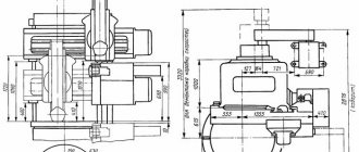
| Dimensions and weight of the machine | ||
| Machine dimensions (length x width x height), mm | 2750 x 2975 x 4100 | 3170 x 3030 x 4100 |
| Machine weight, kg | 16 500 | 20 000 |
What other features does the equipment have?
The following technical indicators of the units should be the main ones for buyers.
- Section of the washer.
- The speed at which the crossbar moves, specified for machines with two posts.
- Maximum distance of movement of supports, horizontal and vertical.
- Section with the height of the part to be processed.
- The number of revolutions of the faceplate.
- The angle for tilting the faceplate.
- Number of speeds.
- General power.
You can download the machine passport here.
When parts are processed by rotary mechanisms, high speeds are typically maintained. Serious cantilever loads do not harm the spindle; the use of a faceplate prevents damage. This part is placed on the structure in a special way to achieve the best result.
The movement of the calipers is the same as the feed movement. The main movement is the rotation of the product, which is fixed in the faceplate. But so-called additional movements are also used. Thanks to this mechanism, the workpiece being processed is as close as possible to the tool that does the main work. Typically the movement of the machine cross beam is used.
16.5-25 meters is the standard diameter of parts processed by two-column types of units. If the configuration is complex, then units equipped with CNC are most suitable. Even difficult boring and turning of surfaces are carried out without problems. The process should not be affected by the presence of straight or curved generatrices.
The calipers on the side are not installed on CNC equipment. The software complex controls the main movement drive; almost all work is carried out automatically. The following features are available to owners of numerical software:
- Tools on the upper support are easy to control when moving.
- The cutters allow the use of a zero position.
- The feed rate and the position of the working tools are adjusted.
- The turret head rotates to the desired position, additional fixation.
- Possibility to independently choose the amount of rotation of the faceplate.