Information about the manufacturer of the tabletop drilling machine NS-12
The developer of the tabletop drilling machine model NS-12 is the Special Design Bureau of Special Machine Tools SKB-3, Odessa . SKB-3 was created in 1947 and existed until the mid-90s.
The machine was produced by machine tool factories and several vocational and technical schools of the Soviet Union in the 50s..70s of the last century.
The NS-12 desktop drilling machine has several modifications (NS-12, NS-12A, NS-12B, NS-12M), which differ slightly from each other in design and configuration.
Production of SHU in Russia
Some of the spindle components required to complete machine tools are produced by domestic manufacturers at their own machine-tool manufacturing facilities, relying on the developments and experience of Soviet industry. There are practically no problems with the manufacture of conventional drive spindle units for a milling machine or turning units that are not oriented towards high-precision processing. However, modern high-tech electrospindles are produced in Russia only in parts and based on imported components. These restrictions are associated not only with the lack of advanced technologies in this area, but also with a shortage of qualified personnel who must solve engineering, technical and production problems.
NS-12 tabletop drilling machine. Purpose and scope
The machine is designed for drilling holes in small parts made of cast iron, steel, non-ferrous alloys and non-metallic materials in industrial enterprises, repair and household workshops.
NS-12 machines allow you to perform the following operations:
- drilling
- countersinking
- deployment
- reaming
- thread cutting
Main parameters of the NS-12 drilling machine:
- Maximum drilling diameter: Ø 12 mm
- Maximum drilling depth: 100 mm
- Maximum height of workpiece: 400 mm
- Distance from spindle axis to column (spindle overhang): 185 mm
- Spindle speed: 450, 710, 1400, 2500, 4500 rpm
- Electric motor power: 0.6 kW
- Machine weight: 121 kg
The drilling depth is measured using a flat scale or stop.
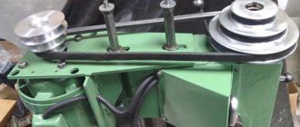
Five-speed drive pulleys allow five spindle rotation speeds, which provides free choice of cutting speeds.
The original design of the belt drive tension allows you to quickly change the position of the belt on the pulleys to obtain the desired cutting speed.
The spindle assembly of the NS-12 drilling machine is the most complex and precise assembly in the machine. The spindle assembly is mounted in the spindle head. Main parts of the spindle assembly:
- Spindle - a shaft that rotates on 2 angular contact bearings inside the spindle sleeve;
- The spindle sleeve (quill) is a cylinder that is mounted in the spindle head and has the ability to move axially within 100 mm.
The upper part of the spindle has splines to receive rotation from the take-up pulley, the lower part has a Morse taper for attaching the drill chuck.
The spindle of the NS-12 machine receives five rotation speeds from five-stage drive pulleys, which provides free choice of cutting speeds of 450, 800, 1410, 2490, 4430 rpm.
The quill, inside which the spindle rotates, has a stroke of 100 mm and is balanced by a spiral spring, which returns the quill to the upper (original) position. The quill is raised and lowered by a rack and pinion. The maximum cutting force allowed by the mechanism is 70 kg.
The end of the spindle of the NS-12 drilling machine is an internal Morse cone No. 1, D = 12.065 mm according to GOST 25557 (Tool cones). To install a standard drill chuck with a shortened cone on the machine, you need to install a mandrel in accordance with GOST 2682 (Mandrels with a Morse taper for drill chucks).
On the NS-12 machine you can install one of 4 mandrels in accordance with GOST 2682:
- Mandrel 6039·0002 - version 2, shortened Morse taper B10
- Mandrel 6039·0005 - version 2, shortened Morse taper B12
- Mandrel 6039·0007 - version 2, shortened Morse taper B16
- Mandrel 6039·0011 - version 2, shortened Morse taper B18
So, using one of the 4 mandrels, you can install a drill chuck of one of 6 standard sizes in accordance with GOST 8522 (Three-jaw drill chucks).
- Chuck 4 - shortened Morse taper B10 , clamping range - 0.5..4 mm
- Chuck 6 - shortened Morse taper B12 , clamping range - 0.5..6 mm
- Chuck 8 - shortened Morse taper B12 , clamping range - 1.0..8 mm
- Chuck 10 - shortened Morse taper B16 , clamping range - 1.0..10 mm
- Chuck 13 - shortened Morse taper B16 , clamping range - 1.0..13 mm
- Chuck 16 - shortened Morse taper B18 , clamping range - 3.0..16 mm
An example of a symbol for a 3-jaw drill chuck, size 16, with a connecting conical hole B18:
Cartridge 16-B18 GOST 8522-79
Morse cone instrumental shortened
Tool taper - Morse taper is one of the most widely used tool mounts.
It was proposed by Stephen A. Morse around 1864. The Morse taper is divided into eight sizes - from KM0 to KM7 (in English: MT0-MT7, in German: MK0-MK7).
Morse taper standards: GOST 25557 (Tool cones. Main dimensions), ISO 296, DIN 228. Cones made according to inch and metric standards are interchangeable in everything except the shank thread.
For many applications, the length of the Morse cone turned out to be excessive. Therefore, a standard was introduced for nine standard sizes of shortened Morse cones (B7, B10, B12, B16, B18, B22, B24, B32, B45), these dimensions were obtained by removing the thicker part of the cone. The number in the designation of a short cone is the diameter of the thick part of the cone in mm.
Russian standard for shortened cones GOST 9953
Tool cones are shortened.
Russian standard for drill chucks GOST 8522
Three-jaw drill chucks.
- B7 - Morse cone KM0 , D = 7.067 mm;
- B10 - Morse cone KM1 , D = 10.094 mm. Cartridge 4-B10 (0.5÷4 mm);
- B12 - Morse cone KM1 , D = 12.065 mm. Cartridge 6-B12 (0.5÷6 mm), Cartridge 8-B12 (1÷8 mm);
- B16 - Morse cone KM2 , D = 15.733 mm. Cartridge 10-B16 (1÷10 mm), Cartridge 13-B16 (1÷13 mm);
- B18 - Morse cone KM2 , D = 17.780 mm. Cartridge 16-B18 (3÷16 mm);
- B22 - Morse cone KM3 , D = 21.793 mm. Cartridge 20-B22 (5÷20 mm);
- B24 - Morse cone KM3 , D = 23.825 mm;
- B32 - Morse cone KM4 , D = 31.267 mm;
- B45 - Morse cone KM5 , D = 44.399 mm.
Where D is the diameter of the cone in the main plane.
Analogues of the desktop drilling machine NS-12
2M112 - Ø12 - Kirov Machine Tool Plant, Kirov
NS-12A - Ø12 - Vilnius Machine Tool Plant
NS-12B, NS-12M - Ø12 - Barnaul Machine Tool Plant
ENS12 - Ø12 - Yeysk machine tool plant ESZ, Yeysk
OD71 - Ø12 - Orenburg Machine Tool Plant, Orenburg
NS-12B, NS-12-M - Ø12 - Barnaul Machine Tool Plant
SHUNSS-12 - Ø12 - Mukachevo Machine Tool Plant, village. Kolchino
GS2112 – Ø12 – Gomel Machine Unit Plant
ZIM1330.00.00.001 - Ø12 - Maslennikov Plant, ZIM-Machine Tool Builder, Samara
MP8-1655 - Ø12 - Machine Tool Plant named after. Kirov, Minsk
BS-01 - Ø12 - Bevers, Berdichev
VS3-5016 - Ø12 - Voronezh Machine Tool Plant
R175M - Ø12 - Chistopol AutoSpetsEquipment plant, Chistopol
Р175, Р175М – Ø13 – AutoSpetsEquipment
VI 2-7 - Ø14 - Volgograd Tool Plant
MD-23 – Ø14 – Kaunas Machine Tool Plant
Types of industrial machines - the whole range of hole drilling work
The vast majority of all industrial machines offered on the market are capable of solving any problem, although this does not apply to certain specialized modifications. In addition to drilling, they can be used to perform some other operations. If we consider equipment intended for metalworking, it can be classified into the following types:
- Tabletop . These devices are designed for creating and processing holes with small diameters. Their design is initially designed for maximum tool diameters of 3, 6, 12 and 16 mm.
- Vertical drilling , which are often referred to as column ones. Their main purpose is to process holes with a diameter of 18, 25, 35, 50 and 75 mm. Equipment of this type is often used in situations where it is necessary to process workpieces and parts of small size in repair shops, as well as in small-scale and individual production.
- Radial drilling . They have become widespread for processing massive and oversized workpieces. They can also be used to process parts with circular holes. This effect can be achieved thanks to the large spindle reach, which has a value of 1300–2000 mm. It is worth noting that the axes of the tool and the holes are aligned by moving the spindle, and the workpiece does not change its position.
- Coordinate drilling . These devices have become widespread for processing parts for which it is important to maintain the exact placement of holes in relation to each other.
- Horizontal drilling . They are used for processing deep holes, the need to create which may arise, say, in shafts, axles, rods, barrels of artillery and rifle systems.
- Central . With their help, you can create center holes, the location of which is the ends of the workpieces.
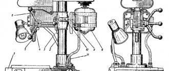
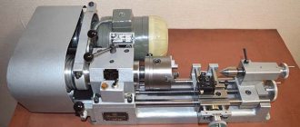
General view of the drilling machine NS-12
Photo of drilling machine NS-12
Photo of drilling machine NS-12
Photo of drilling machine NS-12
Manufacturing features when using a screwdriver
The process of making a drilling machine using a screwdriver is absolutely similar to how it is done when using an electric drill.
The use of a power supply and the ability to connect to a 220 Volt network “give” the screwdriver a second life
A screwdriver may not be in demand if the batteries fail, so the optimal solution for resuming operation would be to create a drilling machine using it, and to connect it to the electrical network, an adapter that provides operation at a voltage of 220 Volts. The main nuances when creating such a design are the following points:
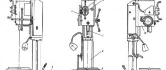
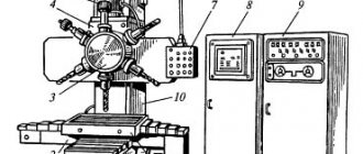
Location of components of the drilling machine NS-12
Location of components of the drilling machine NS-12
Specification of components of the drilling machine NS-12
- Plate
- Column
- Trunk (spindle head)
- Spindle sleeve (quill)
- Spindle
- Spindle quill feed handle
- Rack
- Electric motor
- Electric motor plate (sub-motor plate)
- Belt tensioner stopper
- Shoe (bracket for fastening the column to the plate)
Brief description of the design and operation of the NS-12 desktop drilling machine
The machine consists of the following main parts: plate 1; column 2; trunk with spindle group 3; electrical equipment 8.
to the plate , in the hole of which a column 2 is installed. The column is secured by tightening the shoe.
Along the perimeter of the plate there is a trench for collecting coolant. At the bottom of the chute there is a drain hole with a plug. When connecting the machine to a centralized supply of emulsion, instead of a plug, a nipple with a rubber hose can be wrapped.
A step-down transformer and a package switch housing (for local lighting) are mounted inside the plate, and a push-button station is installed outside (for the machine’s electric motor).
to the column (Fig. 4) (m = 2), in mesh with which there is a gear mounted in the trunk, rigidly fixed to the handle 4 (see diagram of the location of the controls). When turning handles 3, 4 (Fig. 6), the trunk moves along the column. After installing the trunk to the required height, handle 3 clamps the trunk.
A spindle group 5, an electric motor 8 with a plate and a tensioner 10 for the V-belt are attached to the trunk
The spindle , unloaded from the pulley, is installed in sleeve 4 (quills) on precision angular contact bearings.
The sleeve moves when handle 6 is turned (Fig. 1).
The transmission of rotation from the pulley to the spindle is carried out using two parallel keys.
The five-speed spindle pulley is secured by a bushing on two radial bearings.
The electric motor is mounted on a sub-motor plate, the guides of which freely fit into the corresponding bores in the trunk.
After the belt is thrown onto the corresponding pulley stage, this plate is pulled away from the trunk to the normal belt tension and in this position is fixed with clamping screws.
Essential elements
The most diverse elements of a technological operation are distinguished. The main ones are the following:
- Installation. This part of the technological operation, performed with constant fastening, is carried out at the very beginning. Quite a lot of attention is also paid to it, since mistakes made can cause the workpiece to shift during processing.
- Position. The completed part of the technological operation, characterized by constancy, must be carried out while fixing the position of the workpiece. It is worth considering that at this stage, the assembly of technological equipment, which is responsible for the direct fixation of the workpiece, can also be carried out.
- Technological transition. The technological transition process can be carried out within one operation without changing previously established operating modes. It is carried out in the case when processing of the workpiece cannot be completed due to insufficient functionality of the equipment. The number of transitions largely depends on how complex the workpiece is. The numbering of transitions is carried out taking into account the sequence of machining of the workpiece.
- Working progress. It is this element of the technological operation that is considered the most important, since it ensures the mechanical removal of material from the surface to give the required shape and size. As a rule, the tool moves relative to the surface of the workpiece with given parameters at a certain depth of the cutting edge into the material being processed. Also, during the working stroke, surface treatment is provided to obtain a certain roughness. The working stroke can be longitudinal or transverse, and the cutting depth and speed, as well as many other parameters, are determined. As a rule, it is longer and more precise, designed to exert a serious mechanical impact on the working body.
- Auxiliary move. It is also an integral part of the technological process. The auxiliary stroke is represented by a single movement of the tool relative to the workpiece, but this does not change the shape, size and other parameters of the workpiece. An auxiliary stroke is used in most cases to displace the main organs relative to the workpiece. An example is the supply of a tool to the cutting zone, as well as a fixing element.
- Setup. Before actual production, adjustment of the equipment, as well as the equipment used, is carried out. Setup involves installing all devices, checking the size of the tool and their position. Quite a lot of attention is paid to the adjustment process, since incorrect fixation of the tool can lead to very serious consequences. The most difficult thing is to set up CNC machines, since they must ensure high processing accuracy. In addition, often the final stage of the adjustment is control processing of the workpiece, during which accuracy and other aspects are determined.
- Adjustment. Another auxiliary process can be called adjustment, which is extremely rare. It involves the adjustment of technological equipment or the technological equipment used. In some cases, only after production has been established can it be possible to determine the incorrect positioning of tools and technological equipment.
- Technological equipment. There are also various means of supporting the procedure. This category includes materials and workpieces, as well as the required equipment. There is simply a huge amount of different equipment on sale, which significantly simplifies the task of processing workpieces of various shapes and sizes.
- Technological equipment. This definition is used to determine the technological equipment, without which it is almost impossible to process the workpiece. It can be very different and is selected depending on what procedure is being performed.
In general, we can say that a technological operation is a complex procedure that consists of a fairly large number of different parts
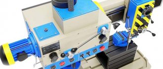
Location of controls for the NS-12 drilling machine
Location of controls for the NS-12 drilling machine
Specification of controls of the NS-12 machine
- Stop button
- Electric motor start button
- Handle for clamping the trunk (spindle head) on the column
- Handle for raising and lowering the trunk (spindle head) along the column
- Quill lifting handle for manual spindle feed
- Tensioner Clamp Screws
- Local lighting switch
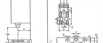
Kinematic diagram of the drilling machine NS-12
Kinematic diagram of the drilling machine NS-12
- Rack on spindle sleeve
- Gear for moving the spindle sleeve
- Gear rack on column
- Gear for moving the trunk (spindle head) along the column
Description of the kinematic scheme
From the electric motor, using a V-belt drive through a five-speed pulley, the machine spindle connected to it by means of keys (and sliding along them) is driven into rotation.
When handle 5 (Fig. 6) is turned, gear 2 (Fig. 4) rotates, which moves rack 1 and the sleeve associated with it up and down.
The sleeve, moving in the cavity of the trunk, moves up and down the spindle, connected to the sleeve by angular contact ball bearings.
The vertical movement of the trunk is carried out by the action of gear 4 (Fig. 4), driven into rotation by handle 4 (Fig. 6), on rack 3 (Fig. 4), mounted on the column.
If necessary, it is possible to rotate the column together with the trunk around its axis after loosening the clamp of the shoe in which the column is secured.
The belt guard casing is either cast or welded (extended).
Spindle bearings for drilling machine NS-12
The spindle of the NS-12 machine is mounted in a sleeve on 2 ball angular contact bearings:
- Bearing No. 36203 GOST 831-41 angular contact ball, accuracy class P, size 17x40x12 mm
- Lower bearing No. 36203 GOST 831-41 angular contact ball, accuracy class B, size 17x40x12 mm
The take-up pulley is mounted on two radial ball bearings:
- Bearing No. 205 OST 6121-39 single-row radial ball, size 25x52x15 mm
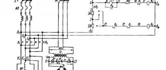
Electrical equipment and electrical circuit of the drilling machine NS-12
Electrical diagram of the drilling machine NS-12
Electrical equipment of the drilling machine NS-12
The electrical equipment of the machine consists of:
- electric motor 0.6 kW
- push-button starter with “Stop” and “Start” buttons
- local lighting with step-down transformer and package switch
Control of the NS-12 machine
1. By pressing the “Start” button of the push-button starter, the electric motor is turned on. By pressing the “Stop” button of the gearbox push-button starter, the electric motor is turned off.
2. By turning the handle of the packet switch VO, the local lighting of the LO is turned on. The machine must be grounded.
Drive of the machine NS-12
The electric motor is attached to the spindle head by means of a submotor plate. On the axis of the electric motor there is a stepped pulley, which is connected to the spindle pulley by a V-belt.
Local lighting of the NS-12 machine
The machine is equipped with equipment for local lighting. Due to the fact that the tabletop drilling machine, model NS-12, is most often installed on workbenches or tables, therefore, the fittings (bracket) and the apparatus (transformer) for local lighting, when installing the machine, must be attached near the machine, and if the machine is installed near walls - then to the last one.
Device
The spindle is a steel shaft, in front of which there is a mount for the working tool. In the classic style, the spindle is mounted on high-precision rolling bearings. To ensure the required accuracy of operation during operation, a special ring is installed on the spindle support. The ring is adjusted using an adjusting nut, which, when tightened, moves the nut along the spindle, which ensures the elimination of gaps formed during operation.
The design of the spindle depends on many factors, usually on the application, the type and design of the machine, the size and speed of operation. Previously, the basis of this unit was bearings, the deviation on which reached 1 micron. Today, the requirements for spindles have increased, so modern samples are made using magnetic or air supports. This solution makes it possible to achieve a minimum deviation not exceeding 0.2 microns.
For higher precision, at which the processing error is below 0.03 µm, a special drive method is used. The spindle is driven and accelerated by the flywheel, but the work is performed after the flywheel is turned off and the spindle operates due to inertia.
The design of the unit must meet the following requirements:
- Accuracy. It is selected based on the machine model, the material being processed and technological requirements.
- Speed. Different types of spindles rotate at different speeds, the faster the speed of processing the workpiece, the higher the quality of the work performed.
- Rigidity. It is determined by the ratio of the spindle deflection and the level of radial runout. The lower this indicator, the higher the quality of work.
- Durability. The service life of the unit primarily depends on the quality of the bearing used.
- Vibration resistance. The spindle must be vibration tolerant to the external vibration of the machine, which ensures high precision of the tool.
- Permissible heating. It is determined by the maximum heating temperature of the unit at which the operating characteristics of the spindle do not change.
- Load bearing capacity. Characterizes the recommended weight and dimensions of the working tool.
Typically the spindle is not considered as a separate structure. Most often, the entire complex of a screw-cutting lathe is considered, including an electric motor, drive, headstock and spindle. The electric motor can be changed, even power plants operating on direct current can be used. The main thing is that all components correspond to the electrical circuit of the machine.
Technical characteristics of the NS-12 machine
| Parameter name | NS-12 | NS-12B | NS-12M |
| Basic machine parameters | |||
| Largest drilling diameter, mm | 12 | 12 | 12 |
| The greatest distance from the end of the spindle to the table | 20..420 | 100..400 | 300 |
| Distance from the axis of the vertical spindle to the rack guides (overhang), mm | 185 | 200 | 200 |
| Desktop | |||
| Width of the working surface of the table, mm | 360 x 360 | 300 x 350 | 300 |
| Number of T-slots Dimensions of T-slots | 3 | 3 | |
| Spindle | |||
| Maximum movement of the spindle head, mm | 300 | 200 | |
| Spindle sleeve stroke, mm | 100 | 100 | 100 |
| Spindle speed, rpm | 450, 710, 1400, 2500, 4500 | 450, 800, 1410, 2490, 4430 | 880, 1500, 2880 |
| Number of spindle speeds | 5 | 5 | 3 |
| Spindle taper | Morse 2 | Morse 1 | B18 |
| Drive unit | |||
| Main motion drive electric motor, kW | 0,65 | 0,6 | 0,37 |
| Dimensions and weight of the machine | |||
| Machine dimensions (length width height), mm | 770 x 465 x 700 | 760 x 470 x 955 | 810 x 450 x 910 |
| Machine weight, kg | 121 | 130 | 140 |