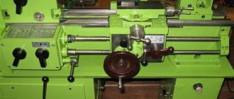
The Rostov educational equipment plant began producing the TV 4 school lathe back in the early 1970s. To this day, it is used to teach schoolchildren and students, and is also often found in personal workshops and small businesses. This versatile device has many positive user reviews and is suitable for hobby use. It allows you to perform such types of work as:
- turning the surfaces of cylinders and cones – internal and external;
- end processing;
- cutting threads with a cutter or tap;
- segment;
- drilling holes.
The operation of the unit is carried out by rotating the blank in the chuck or centers. The main working shaft of the device rotates due to a belt drive obtained from an electric motor. When performing turning operations, the cutters are brought to the workpiece due to the secondary feed movement.
Information about the manufacturer of the educational screw-cutting lathe TV-4
The manufacturer of the screw-cutting lathe model TV-4 (TV4) is the Rostov plant of small-sized machine tools MAGSO , founded in 1956.
ComTech Financial and Industrial Group , which has existed in the machine tool equipment market for several years and has priority in the production of small-sized metal-cutting machines: lathes, milling, vibrating, sharpening, drilling, which equip schools, vocational schools, colleges, institutes, repair and installation organizations of all regions of Russia.
Another manufacturer of the TV-4 machine was the Dubno Foundry and Mechanical Plant - the city of Dubno, Rivne region in Ukraine.
Machines produced by the Rostov plant of small-sized machine tools MAGSO
- TV-4
- educational screw-cutting lathe Ø 200, RMC 350 mm - TV-6
- educational screw-cutting lathe Ø 200, RMC 350 mm - TV-6M
- educational screw-cutting lathe Ø 200, RMC 350 mm Dubno - TV-7
- educational screw-cutting lathe Ø 220, RMC 330 mm - TV-7M - educational screw-cutting lathe Ø 220 mm, RMC 275 mm
- TV-9 - educational screw-cutting lathe Ø 220 mm, RMC 525 mm
- TV-11 - educational screw-cutting lathe with frequency converter Ø 240, RMC 750 mm
- NGF-110Sh4 - low power milling machine 0.75 kW, table size 100x400 mm
- NS-16 - tabletop drilling machine Ø 16
- SNVSH-1 - tabletop drilling machine Ø 12
Equipment Features
Student metal lathes have bridged the gap between amateur tools and professional production equipment. They received their name Shkolnik for their active use for teaching students in vocational schools and high school students in labor lessons.
All models, from TV2 to the modernized 16U04P with increased accuracy, have common characteristics for school lathes:
- small dimensions;
- simplicity of design;
- safety at work;
- manual control and easy maintenance;
- processing of small-sized workpieces;
- low productivity;
- impossibility of producing batches of parts.
Lathe 16U04P
Training models were produced as floor-mounted ones with cast pedestals and table-top ones with only mounting platforms in the form of wide legs under the frame. They can be installed on a workbench in a workshop and study the principle of operation of a lathe, gaining skills in working as a turner.
The design of the lathe is simplified. There is no gearbox. Speeds are changed by rearranging the gears and flipping the belt. The caliper slide can be moved manually in one direction only. There is no ability to sharpen cones at a given angle.
Taking into account the specificity of Shkolny metal lathes, they were equipped with casings and screens that eliminate the possibility of injury from rotating parts or flying chips. As soon as the guard rose, the cartridge stopped.
The lathe was designed only for training. It can accommodate small workpieces up to 10 kg and rolled products up to 16 mm.
There is no space for large-diameter parts in the frame. The maximum workpiece diameter is up to 200 mm. The center-to-center distance on most models is 220 - 350 mm, and only shafts with lengths of 525 and 750 mm can be installed on modernized machines.
Moving the caliper and slide along the dial manually did not allow us to work quickly and make batches of parts. Most Shkolnik series machines have 6 chuck rotation speeds from 120 to 975 rpm. The direction of rotation is switched by the motor.
TV-11 machine diagram
Despite their simplicity, training lathes provide good finishing. They can be used to sharpen parts with an accuracy of 0.05 mm and perform turning for grinding. The gearbox connected to the screw contains thread cutting with 3 pitch sizes on early models and 6 threads on modernized machines, starting with TV7.
Teenagers were taught carpentry on TV4 and on a specially produced wood lathe Shkolnik series STD-120. Using this equipment, those who like to make furniture with their own hands at home make curly legs, stands and other round elements.
Currently, compact lathes are used in mobile workshops to produce parts for repairs. Craftsmen willingly buy compact equipment for home use.
TV-4 (TV4) Training screw-cutting lathe. Purpose, scope
The TV-4 screw-cutting lathe replaced in production the obsolete first school screw-cutting lathes TVSh-2 and TVSh-3 (TV-3) and was produced in the 70s of the last century. The TV-4 machine was replaced by a more advanced model TV-6
The TV-4 lathe is an educational universal screw-cutting lathe and is intended for all kinds of turning work in workshops of schools for polytechnic training and cold metal cutting.
The educational screw-cutting lathe TV-4, despite its simplified design, has all the components of an “adult” screw-cutting lathe: spindle speed box, guitar, feed box, drive shaft and lead screw, caliper with mechanical feed.
The machine allows you to perform the following types of turning work:
- Grooving and boring of cylindrical and conical surfaces
- End trimming
- segment
- Metric thread cutting
- Drilling and a number of other works
Operating principle and design features of the machine
The front end of the spindle of the TV-4 machine has an M36x4 thread for installing an intermediate flange with a chuck (see the article Lathe chucks). The standard chuck for the TV-4 machine is Ø100 mm.
The spindle of the TV-4 lathe receives 6 stages of rotation (120, 160, 230, 375, 500, 710 rpm) from the gearbox in the headstock.
The gearbox, by switching gears, allows you to reduce the spindle speed required for tapping, as well as for heavy work that requires increased torque. Higher spindle speed is used for finishing work.
The machine is driven by an asynchronous electric motor ~220 V. Through a V-belt transmission and single-stage pulleys, the movement is transmitted to the input shaft of the gearbox. Inside the gearbox, movement is transmitted through gears to the spindle. The spindle, depending on the position of the handles on the headstock, rotates at one of 6 speeds. The direction of spindle rotation is determined by the motor.
From the spindle, the movement is transmitted to the output shaft of the gearbox, then to the guitar, and from it to the input shaft of the gearbox.
The feed box provides 3 caliper feed speeds and can cut 3 metric threads without rearranging gears in the guitar.
At the output of the feed box there is a lead shaft and a lead screw, which rotate alternately at one of 3 speeds.
The lead screw is turned on when cutting threads. The speed of the lead screw is set by the handles on the feed box and determines one of the 3 metric threads (the lead screw can be used in longitudinal feed mode, but is not used so as not to wear it out). The direction of rotation of the lead screw is set by the left handle on the headstock.
The running shaft makes it possible to obtain one of 3 longitudinal feeds of the caliper. The feed speed is set by the handles on the front wall of the feed box.
The lead screw and lead shaft pass through a caliper apron , which converts the rotary motion of the lead screw or lead shaft into forward longitudinal movement of the caliper. Transverse mechanical movement of the support in the TV-4 machine is not provided.
Gearbox lubrication by spraying oil from the oil bath at the bottom of the headstock onto the gears. The feed box is lubricated with a wick from a tray, which is filled with oil once per shift. The apron, caliper, guitar, tailstock and bed are lubricated by hand once per shift.
Main technical characteristics of the school screw-cutting lathe TV-4
Manufacturer - Rostov-on-Don.
The main parameters of the machine are in accordance with GOST 18097-93. Screw-cutting and turning machines. Basic dimensions. Accuracy standards.
- The largest diameter of a Disk-type workpiece processed above the bed is Ø 200 , mm
- The largest diameter of the Shaft type workpiece processed above the upper part of the support is Ø 125 mm
- Distance between centers - 350 mm
- The longest turning length is 300 mm
- Electric motor power - 0.6 kW
- Full machine weight - 280 kg
Spindle of screw-cutting lathe TV-4
- Threaded spindle end - M36x4
- Spindle hole diameter - Ø 16 mm
- The largest diameter of the processed rod is Ø 15 mm
- Spindle speed limits per minute - (6 steps) 120, 160, 230, 375, 500, 710 rpm
- Standard chuck diameter - Ø 100 mm
Feeds and threads of a screw-cutting lathe TV-4
- Limits of longitudinal feeds: — (3 steps) 0.08; 0.1; 0.12 mm/rev
- Limits of metric thread pitches - (3 steps) 0.8; 1; 1.25 mm
Specifications
The electric motor power of the equipment in question is 0.6 kW. At the same time, the total weight of the machine is 280 kg, which allows it to be easily located in domestic conditions.
Main settings
The main parameters of TV-4 include:
- distance between centers – 35 cm;
- longest turning length – 30 cm;
- the maximum diameter of the workpiece processed above the upper part of the support is 125 mm;
- diameter processed above the bed – 20 cm.
The components in the machine are classic, with certain technical characteristics that allow you to perform all turning operations typical for this type of equipment.
Spindle
It is located in the front spindle headstock and its main function is to rotate the workpiece using a three-jaw chuck. It receives 6 digits of revolutions from the receiving pulley. Maximum – 710 rpm.
The largest diameter of the processed rod on the spindle is 15 mm. The end of the spindle is threaded – M36x4.
Caliper and feed
Designed to move the cutting tool. Has 4 carriages:
- The first one moves in the direction of the bed.
- The second one moves along the transverse guides of the first carriage, moving the cutting tool in the transverse direction.
- The third one rotates 45 degrees from the middle position in both directions.
- The fourth one carries the tool holder and moves in the longitudinal direction along the third carriage.
Cutting slide
According to the technical characteristics, the incisor slide assumes a displacement of 5 cm.
Tailstock
She is also called a stubborn grandmother. This is a structural part whose main function is to support the second end of the workpiece using the center. She fixes the future detail.
It is located on a base that moves evenly along the frame guides. The thrust headstock contains a quill that moves in the longitudinal direction. Its movement is carried out by a flywheel.
Electrical equipment
The drive is carried out from an asynchronous electric motor ~220V. Through clinometer gears and a single-stage pulley, the movement is transmitted to the running shaft and gearbox.
Electrical equipment also includes an electrical panel, transformer, and fuse links. The electrical panel and magnetic starter are located in the right cabinet, and the electric motor itself with a push-button station is in the left.
General dimensions (dimensions) and weight
The machine belongs to the light class of equipment. Its parameters in mm are 1100x470x1020. Processing accuracy class H, which allows an error of no more than 10 microns.
Thanks to its comfortable size, it is even suitable for installation in an apartment or on a balcony. That is why the machine is popular among household craftsmen.
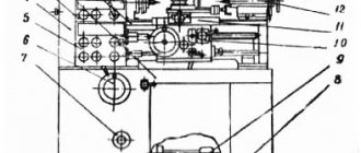
Location of controls for the TV-4 lathe
Location of controls for the TV-4 lathe
Plates for control knobs of a TV-4 lathe
Specification of controls for the TV-4 screw-cutting lathe
- Spindle speed setting handle
- Spindle speed setting handle
- Handle for setting the cutting of right and left threads and changing the direction of feeds
- Handle for setting the feed rate and thread pitch
- Roller shift knob
- Flywheel for manual movement of the longitudinal carriage
- Rack and pinion on/off button
- Longitudinal mechanical feed switch handle
- Lead screw nut engagement handle
- Handle for manual movement of the cross slide
- Cutting head mounting handle
- Tailstock quill fastening handle
- Tailstock quill movement flywheel
- Step-down transformer for local lighting
- Batch switch for local lighting
- Safety block
- Reversing magnetic starter
- Reversible button to start and stop the machine
- Lamp
- Handle for attaching the tailstock to the bed guides
- Batch network switch (general)
- Protective screen
TV-4 machine control
Starting and stopping the machine’s electric motor is done by pressing the “start” and “stop” buttons.
Depending on the nature of the work on the machine, the handles and control levers must be in certain positions (see Fig. 1).
I. Position of handles and levers when working on thread cutting (mechanical feed by lead screw)
- On the headstock - the position of the snaffle handle 3 depending on the desired direction of feed of the caliper (“L” - left or “R” - right).
- On the feed box - the position of the feed box lever 4 depending on the selected feed amount. Lever 5 “screw - shaft” - in the right position - “Screw”.
- On the apron is the handle of the self-propelled gun 8 in the lower off position “pull away”.
- Rack gear engagement handle 7 is in the “pull” position.
- The handle for turning on the uterine nut 9 is in the lower extreme position.”
Position of handles and levers when working with the drive shaft (mechanical feed)
- On the headstock - the position of the snaffle handle 5 depending on the desired direction of feed of the caliper (left or right).
- On the feed box - the position of the feed box lever 4 depending on the selected feed amount. Lever 5 “screw - shaft” - in the left extreme position - “shaft”.
- On the apron is the self-propelled handle 8 in the “pull” position.
- The handle for turning on the uterine nut 9 is in the upper position.
- Rack gear engagement handle 7 is in the “pull” position.
Position of handles and levers during manual longitudinal feed with a roller
- On the headstock - the position of the bit handle 3 is in the middle position “H”.
- On the feed box, the position of the screw-shaft lever is indifferent.
- On the apron is the self-propelled handle in the off position. The lever of the uterine nut is in the upper position.
Purpose of the machine
Initially, it was planned to perform the entire range of turning operations on the school model. That is why the TV-4 design has the classic layout of all machines of this type. The following turning operations are performed on it:
- Boring and turning of steel workpieces by rotation.
- High precision end trimming.
- Drilling.
- Thread cutting (metric).
In order to increase functionality, equipment is being modernized. However, you can start this only after familiarizing yourself with the specific design and technical characteristics. Modernization should not adversely affect the performance and safety of operation of the machine.
The differences between training equipment are its layout and the location of controls, which should be such that a short teenager can operate the machine without difficulty.
Kinematic diagram of the TV-4 screw-cutting lathe
Kinematic diagram of the TV-4 screw-cutting lathe
Specification of bearings for the TV-4 lathe
Purpose of the equipment
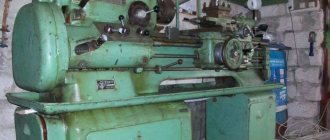
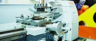
Appearance
One of the fundamental rules for designing such equipment is its safety and ease of setup. But at the same time with these conditions, during the work process, students must familiarize themselves with the design using a clear example and learn the basic rules of working on a TV-4 lathe.
Initially, the school model was intended to perform the entire range of turning operations. To achieve this, its design has a classic layout typical for machines of this type. The following types of turning work can be done on TV-4:
- turning and boring of steel blanks using the rotation method;
- cutting ends with high precision;
- thread cutting. However, it should be taken into account that the machine is designed only for the formation of metric threads;
- drilling
To increase the functionality of the equipment, it is necessary to modernize it. This can only be done after a detailed study of the specific design and technical characteristics. Each type of modernization should not negatively affect the performance of the machine or the safety of working on it.
One of the properties of educational equipment is its layout and location of controls. They are designed in such a way that work on the machine is not difficult due to the short stature or length of the arms of teenagers.
Design of the main components of the TV-4 screw-cutting lathe
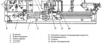
A screw-cutting lathe consists of the following main components: front stand, rear stand, bed, headstock, feed box, guitar, apron, caliper, tailstock, protective casing, trough, electrical equipment, protective screen.
Front cabinet
The front cabinet is U-shaped with stiffening ribs in the upper and lower parts.
The drive electric motor is installed on the back side of the cabinet, on the front there is a reversible button for turning the electric motor on and off.
Rear cabinet
The rear cabinet is U-shaped with stiffening ribs in the upper and lower parts. A panel with the electrical equipment of the machine is mounted in the rear cabinet.
Machine bed
The bed serves to support, secure and interconnect all components of the machine.
The machine bed is box-shaped with windows. Has two prismatic guides.
The front guide is used to move the carriage, the rear guide is used to move the tailstock.
A lead screw and rack are installed on the front side of the frame
The bed is installed on two pedestals.
Headstock of screw-cutting lathe TV-4
Drawing of the headstock of a TV-4 lathe
Drawing of the headstock of a TV-4 lathe
Headstock of screw-cutting lathe TV-4
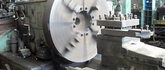
Photo of the headstock of the TV-4 screw-cutting lathe
Photo of the headstock of the TV-4 screw-cutting lathe
Photo of the headstock of the TV-4 screw-cutting lathe
Photo of the headstock of the TV-4 machine. Option with shortened drive shaft
The headstock (Fig. 2 and 3) is attached to the left side of the bed. The gearbox is installed along the center line in the horizontal plane by two setscrews and nuts.
The movement of the gearbox is transmitted from an individual electric motor through a V-belt transmission to a pulley. The headstock serves to support the workpiece and impart rotational motion to it. In a TV-4 type machine, the headstock is also a gearbox, so this term will be used in the future.
Inside the box, the movement is transmitted through shaft 2 and gear 3, which sits motionless on the shaft, to shaft 4, on which the motionless gear 12 and block gear 5 sit; gear 6 is involved only in the operation of the bit.
On shaft 7 there are block gears 8 and 11, which move on the shaft along the key using handles 1 and 2 (Fig. 1). The handle / has three positions, obtained by turning to the right and left. Handle 2 has two positions.
The triple block gear 8 has the ability to be in constant mesh with block 5 or gear 12 and thereby transmit movement to shaft 7 and block gear 13, located directly on the spindle of the machine 14.'
The spindle transmits the rotation of the workpiece using a three-jaw chuck or a faceplate with a driver, which rotates onto its threaded part. When machining parts on centers, a center is inserted into the spindle.
A device is mounted in the gearbox that allows you to change the direction of rotation of the lead screw and the lead shaft, i.e., change the direction of movement of the caliper. This is done by moving gear 15 to the left and right extreme positions using handle 3 (Fig. 1).
In the left extreme position of the handle, gear 15 will receive direct rotation directly from the gear block 16 located on the spindle. When the handle is in the extreme right position, gear 15 will receive reverse rotation due to engagement with idler gear 6, which in turn receives rotation from the second stage of gear block 16.
The rotation of shaft 17 is transmitted to gear 18, which is in constant engagement with the gears of the transmission mechanism and then with the feedbox mechanism.
With the handle and gear 15 in the middle neutral position, rotation from the spindle will not be transmitted to the feed box, i.e. neither the lead screw nor the lead roller will rotate.
The headstock spindle receives six revolutions from the take-up pulley. A table indicating the spindle revolutions per minute depending on the position of the handles is placed on the top cover of the feed box.
The front spindle journal rotates in two radial thrust bearings, and the rear journal rotates in a radial bearing. To regulate the axial tension, two nuts are installed on the spindle. To fix the axial movement of the rollers, adjusting screws 10 are installed on the front cover of the gearbox. There is an oil level indicator on the front side of the gearbox, and an oil drain plug 22 on the rear wall.
Front and rear spindle supports for TV-4 lathe
The spindle of the TV-4 machine is mounted on 3 bearings:
- Front spindle support - two single-row angular contact ball bearings No. 46207, accuracy class H, size 35x72x17 mm
- Rear support - single-row radial ball bearing No. 206, accuracy class H, size 30x62x16 mm
Bearing No. 46207 (7207)
This is a single row angular contact ball bearing.
Which copes well with both significant radial and axial one-sided loads (up to 150% of the unused permissible radial load). For rigid axial fixation (for example, in machines requiring high processing accuracy) of the shaft, they are installed in pairs. In our country, they are produced at Saratov (3 gas processing plants) and Samara SPZ-4 (4 gas processing plants).
If earlier bearings of this type with a high degree of accuracy were widely used, now only the sixth, which is why only two modifications are produced - 6-46207E5, 6-46207L (polyamide and brass cages).
Imported bearings of this type are marked 7207A. The brass separator in the number is reflected by the presence of the letter M, and the polyamide separator - the letter D.
Dimensions and characteristics of bearing 46207 (7207):
- Inner diameter (d): 35mm ;
- Outer Diameter (D): 72mm ;
- Width (H): 17 mm;
- Weight: 0.289 kg;
- Ball diameter: 11.112mm ;
- Number of balls: 12 pcs;
- Outer ring flange diameter: 60.2 mm;
- Inner ring flange diameter: 46.9 mm;
- Dynamic load capacity: 29 kN ;
- Static load capacity: 16.4 kN
- Rated speed: 11000 rpm .
Bearing diagram 46207 for TV-4 lathe
Adjusting spindle bearings on a TV-4 screw-cutting lathe
Front spindle support for TV-4 lathe
The radial clearance of the front bearings and the axial clearance of the spindle are adjusted using nut 1 and locknut 2 (Fig. 11).
After adjusting the bearings, you need to check the spindle for radial spin. To do this, a mandrel with a conical shank and a free length of 150 mm must be inserted into the conical hole of the spindle.
Place the indicator button on the centering surface of the spindle and manually press the spindle using the free end of the mandrel.
In this case, the deviation of the indicator needle should not exceed 0.02 mm. In addition, the spindle should be easy to turn.
Transmission mechanism (guitar) of the TV-4 screw-cutting lathe
Guitar screw-cutting lathe TV-4
The transmission mechanism (Fig. 4) is used to transmit rotation from the gearbox spindle to the feedbox. The mechanism consists of a bracket 1 on which gears 7, 4, 2 are mounted. The transmission mechanism is characterized by a gear ratio, and for the TV-4 machine it is:
i = 24/60 * 40/64 = 1/4
For this machine, this gear ratio is constant, since replacement gears are not included with the machine.
Feed box for screw-cutting lathe TV-4
Drawing of the feed box of the TV-4 screw-cutting lathe
Photo of the feed box of the TV-4 screw-cutting lathe
The feed box (Fig. 5) receives movement from the gearbox through the gears of the transmission mechanism. The feed box mechanism makes it possible to obtain metric threads with a pitch of 0.8; 1.0; 1.25 mm and longitudinal feed of the caliper within 0.08; 0.1; 0.12 mm per spindle revolution.
The required threads and feeds are set by turning handle 4 (Fig. 1), located on the front cover of the feed box.
The lead screw or lead roller is turned on by turning handle 5 (Fig. 1).
In the position indicated in Figure 5, the lead screw rotates. When gear 9 moves to the right, it will disengage with gear 10 and engage with clutch 11, which will transmit rotation to the drive shaft.
Thus, the design of the feed box eliminates the possibility of simultaneous rotation of the lead screw and the lead roller.
Changing the direction of rotation of the lead screw and the lead shaft is done by turning handle 3 (Fig. 1).
To lubricate the feedbox mechanism, there is a trough in the upper part for filling oil.
Oil is supplied to the gears and rubbing surfaces by wicks.
During operation, it is necessary to ensure that there is always a small amount of oil in the feed box trough.
Support for screw-cutting lathe TV-4
Drawing of a support for a screw-cutting lathe TV-4
The support (Fig. is designed to secure and move the cutter. The support has four slides.
Slide 1 moves in the longitudinal direction along the frame guides.
Slide 2 moves along the transverse guides of slide 1 and serves to move the cutter transversely.
Slide 4, carrying a four-position cutting head, has only longitudinal movement along the guides of slide 3, which has the ability to rotate 40° from the average position in one direction or another.
Transverse movement of slide 2 along the guides of lower slide 1 is carried out by screw 6 and nut 5.
Screw 6 is rotated by hand using handle 12.
On top, slide 2 has a recess into which the protrusion of the rotating part of the upper support fits; To secure the rotating part, there are 2 bolts, the heads of which fit into the T-shaped groove of slide 2.
The upper slide 4 of the support can be moved along the guides manually using a handle 7, which rotates the screw 8. The guides of the frame, slides and wedges wear out so much from prolonged operation that a gap may appear between them.
Apron for screw-cutting lathe TV-4
Drawing of the apron of the TV-4 screw-cutting lathe
Using the apron (Fig. 7), you can perform mechanical longitudinal feed of the caliper from the lead roller and from the lead screw, as well as manual longitudinal feed.
Manual feed is carried out by rotating the flywheel 1, mounted on the pinion shaft 4, which engages with gear 3, sitting on the shaft of rack and pinion gear 2.
The rack and pinion meshes with a rack that is rigidly attached to the frame. Mechanical feed from the running roller 10 is carried out by a worm 5 connected to the roller by a sliding key. The worm causes the worm gear 11 to rotate and then through the cam clutch and gears 13, 3 the rotation is transmitted to the rack and pinion gear. To turn on the mechanical feed, you need to turn handle 6 towards yourself, and the claw clutch is turned on.
Apron for screw-cutting lathe TV-4
Tailstock of screw-cutting lathe TV-4
Drawing of the tailstock of a screw-cutting lathe TV-4
The tailstock serves to support the second end of the workpiece. Housing 1 is located on base 2, which moves along the guides of the machine bed.
The quill 3 is swept longitudinally in the body.
The quill has a conical hole (Morse taper 2) into which a stop center or other tool is inserted; drills, reamers, drill chuck, etc. The quill is moved by handwheel 4, which rotates screw 5.
Design Features
To increase the reliability of the machine, the stand is made of thick-walled sheet steel and additionally has stiffening ribs. Thanks to this design, the main working units and controls can be placed as ergonomically as possible.
The cabinet is the basis of the structure. In its rear part there is an electric motor necessary to drive the spindle head. On the front panel there is an operation control unit - on/off buttons and the “Reverse” mode. All electrical equipment is also mounted in the rear. An access door is provided for maintenance and repair.
Essential elements:
- The headstock is on the left side of the bed . A box is connected to it to change gears. Structurally, this is one element. Spindle rotation is transmitted using a 3-jaw chuck.
- Transmission . To adjust the feed level, the corresponding handle is turned. The operating scheme excludes the possibility of simultaneous rotation of the lead screw and the roller. A trough at the top is required to supply lubricant.
- Transmission mechanism . Transmits rotation to the gearbox from the spindle unit. For our model, the gear ratio is ¼. It is impossible to install other pairs of gears, so the ratio here is a constant.
During operation, the oil level is constantly monitored to lubricate the gearbox. There must always be at least a minimum of lubrication in the trough, otherwise overheating and gear failures occur.
On the front of the equipment there is a table with possible speed values, which allows you to select the optimal operating mode.
Main technical characteristics of the TV-4 machine
| Parameter name | TV-4 | TV-6 | TV-7 |
| Basic machine parameters | |||
| Accuracy class | N | N | N |
| The largest diameter of the workpiece above the bed, mm | 200 | 200 | 220 |
| The largest diameter of the workpiece above the support, mm | 125 | 80 | 100 |
| Height of centers above flat bed guides, mm | 108 | 108 | 120 |
| Maximum length of the workpiece at centers (RMC), mm | 350 | 350 | 330 |
| Maximum length of the workpiece in the chuck, mm | 310 | ||
| Maximum turning length, mm | 300 | 300 | 300 |
| Maximum height of the cutter holder, mm | 10 x 12 | 12 x 12 | 16 x 16 |
| Height from the cutting surface to the center line, mm | 12 | 12 | |
| The greatest distance from the axis of the centers to the edge of the tool holder, mm | 78 | 78 | |
| Spindle | |||
| Threaded end of spindle, mm | M36 x 4 | M36 x 4 | M45 x 4 |
| Diameter of standard cartridge, mm | 100 | 100 | 125 |
| Diameter of through hole in spindle, mm | 16 | 18 | |
| Maximum rod diameter, mm | 15 | 12 | |
| Morse taper spindle | №2 | №3 | №3 |
| Number of speed steps for direct spindle rotation | 6 | 6 | 8 |
| Spindle direct rotation frequency, rpm | 120, 160, 230, 375, 500, 710 | 130, 170, 235, 385, 510, 700 | 60…1000 |
| Number of spindle reverse rotation frequency steps | 6 | 6 | 8 |
| Spindle reverse rotation frequency, rpm | 120, 160, 230, 375, 500, 710 | 130, 170, 235, 385, 510, 700 | 60…1000 |
| Spindle braking | No | No | No |
| Handle lock | No | No | No |
| Caliper. Submissions | |||
| Maximum longitudinal movement of the caliper, mm | 300 | 300 | 260 |
| Longitudinal movement of the caliper by one dial division, mm | 0,5 | 0,25 | 0,25 |
| Maximum lateral movement of the caliper, mm | 100 | 100 | |
| Transverse movement of the caliper by one division of the dial, mm | 0,025 | 0,025 | 0,025 |
| Maximum movement of the cutting slide, mm | 50 | 85 | 85 |
| Movement of the cutting slide by one division of the dial, mm | 0,025 | 0,025 | 0,025 |
| Angle of rotation of the cutting slide, degrees | ±45° | ±45° | ±40° |
| Number of stages of longitudinal feed of the caliper | 3 | 3 | 8 |
| Limits of longitudinal working feeds of the caliper, mm/rev | 0,08; 0,1; 0,12 | 0,08; 0,1; 0,12 | 0,1; 0,12; 0,15; 0,16; 0,18; 0,20; 0,24; 0,32 |
| Limits of working cross feeds of the caliper, mm/rev | No | No | No |
| Number of metric threads to be cut | 3 | 3 | 6 |
| Limits of pitches of cut metric threads, mm | 0,8; 1,0; 1,25 | 0,8; 1,0; 1,25 | 0,8; 1,0; 1,25; 1,5; 2,0; 2,5 |
| Limits of pitches of cut inch threads | No | No | No |
| Limits of pitches of cut modular threads | No | No | No |
| Limits of pitches of cut pitch threads | No | No | No |
| Tailstock | |||
| Morse taper tailstock | №2 | №2 | №2 |
| Maximum movement of the quill, mm | 65 | 65 | 65 |
| Electrical equipment | |||
| Main drive electric motor, kW | 1,0 | 1,1 | 1,1 |
| Dimensions and weight of the machine | |||
| Machine dimensions (length width height), mm | 1440 x 470 x 1020 | 1100 x 470 x 110 | 1050 x 535 x 1200 |
| Machine weight, kg | 280 | 300 | 400 |
- Passport for the TV-4 screw-cutting lathe, 1969
- Screw-cutting lathe, model TV-4. Care and maintenance manual, GlavUchTekhProm, 1973
- Acherkan N.S. Metal-cutting machines, Volume 1, 1965
- Batov V.P. Lathes, 1978
- Beletsky D.G. Handbook of a universal turner, 1987
- Denezhny P.M., Stiskin G.M., Thor I.E. Turning, 1972. (1k62)
- Denezhny P.M., Stiskin G.M., Thor I.E. Turning, 1979. (16k20)
- Modzelevsky A. A., Muschinkin A. A., Kedrov S. S., Sobol A. M., Zavgorodniy Yu. P., Lathes, 1973
- Ogloblin A.N. Basics of turning, 1967
- Pikus M.Yu. A mechanic's guide to machine repair, 1987
- Skhirtladze A.G., Novikov V.Yu. Technological equipment for machine-building industries, 1980
- Tepinkichiev V.K. Metal cutting machines, 1973
- Chernov N.N. Metal cutting machines, 1988
Bibliography
Related Links. Additional Information
- TV-4 lathe. Video
- School lathes. Review
- Classification and main characteristics of turning
- Selecting the right metalworking machine
- Multi-start thread. Methods for cutting multi-start threads on a lathe
- Graphic signs for lathes
- Friction clutch of a screw-cutting lathe
- Methodology for checking and testing screw-cutting lathes for accuracy
- Directory of lathe manufacturing plants
- Directory of lathes
Home About the company News Articles Price list Contacts Reference information Interesting video KPO woodworking machines Manufacturers
Main components and their features
As mentioned above, the TV4 machine is made according to the classical layout. Its functional and structural components are quite standard and are found in industrial equipment for similar purposes.
- All actuators, drives and other components are mounted on the frame - the main strength base of the structure. It is made of cast iron, using the casting method, and consists of two racks. The left cabinet houses the main drive, an asynchronous motor. An under-motor plate is provided for its fastening. The main drive is powered from a three-phase 380V network; to power the equipment from a single-phase 220V line, a converter must be installed. On the left side of the bed there is a feed box, on the right there is a tailstock assembly.
- The spindle-type headstock unit includes a gearbox. Inside the cast iron housing there is a gear system that receives torque through a V-belt drive. On the front of the spindle there are elements of a three-jaw chuck designed for fixing the workpiece. The machine operating manual provides for pouring oil into the gearbox for proper operation of the unit.
- The guitar is an intermediate unit for transmitting torque from the gearbox to the feed unit. It is a key element of the system that drives the caliper into longitudinal movement. The gear ratio of the guitar is not changeable, it is 1:4.
- The feed box generates torque on the drive roller or transmits force to the screw. Its tasks include changing the rotation speed of dependent devices. The feed box is equipped with a locking mechanism: when moving from the roller to the screw, the power transmission stops. This is done for security purposes. The instructions state that the feed box should be lubricated by oil poured inside the housing.
- A machine support is a rather complex system. Its movement is provided in different types: longitudinal along the frame, along the guides, transverse on its own slide, movement on the upper slide system. For movement in the longitudinal direction there is an automated feed from the machine’s motors, the rest of the mechanics are done manually by rotating the appropriate regulators. This principle of movement allows you to change the position of the cutter. The range of options becomes even greater when you consider that the top slide has a four-position tool post and can be rotated 45 degrees.
The last important functional element of the TV-4 machine design is the apron. The task of this unit is to implement a scheme for converting the rotation of the gearbox shafts into the translational movement of the caliper. The description of the apron's operation also includes thread cutting using it.
The electrical circuits of the machine include several significant zones. The list includes:
- electrical circuit for powering the main drive motor;
- protection system represented by fuses;
- reversible magnetic starter for the main drive;
a step-down transformer with an output voltage of 12V, connected to the electrical equipment for lighting the workplace.
The electrical circuit diagram of the machine is quite simple and, given the existing need for power from a 220V network, can be modified. In particular, it is possible to construct a different connection of the motor stator windings with the installation of starting capacitors. Good results are also achieved by using frequency control of engine speed.