Information about the manufacturer of the vertical drilling machine 2N135
The manufacturer of drilling machines models 2N125, 2N135, 2N150, 2G175 is the Sterlitamak Machine Tool Plant , founded in 1941.
The history of the Sterlitamak Machine Tool Plant begins on July 3, 1941, when the evacuation of the Odessa Machine Tool Plant to the city of Sterlitamak began.
Already on October 11, 1941, the Sterlitamak Machine Tool Plant began producing special modular machines for the defense industry.
Currently, the plant produces metalworking equipment, including CNC lathes and milling machines, multifunctional machining centers.
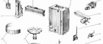
Products of the Sterlitamak Machine Tool Plant
- 2135
— universal vertical drilling machine Ø 35 - 2A125
- universal vertical drilling machine Ø 25 - 2A135
- universal vertical drilling machine Ø 35 - 2A150
- universal vertical drilling machine Ø 50 - 2G175
- universal vertical drilling machine Ø 75 - 2N125
- universal vertical drilling machine Ø 25 - 2N135
- universal vertical drilling machine Ø 35 - 2N150
- universal vertical drilling machine Ø 50 - 2R135F2
- CNC vertical drilling machine Ø 35 - 2S125, 2S125-1 (2S125-01), 2S125-04
- universal vertical drilling machine Ø 25 - 2S132, 2S132K
- universal vertical drilling machine Ø 32 - 2С150ПМФ4
- vertical drilling-milling-boring machine with CNC and ASI 500 x 1000 - 2С550А
– radial drilling machine Ø 36 - 400V
- vertical drilling-milling-boring machine with CNC and ASI 400 x 900 - 500V (STC F55)
- vertical milling center 630 x 1200 - SF-16, SF-16-02, SF-16-05
- tabletop milling and drilling machine Ø 16
Dimensions of the working space of the drilling machine 2N135
Dimensions of the working space of the drilling machine 2N135
| Machine model | Morse cone | A | B | IN | D | D1 | M |
| 2N125 | 3 | 250 | 700 | 60 | 45 | 23,825 | 400 |
| 2N135 | 4 | 300 | 750 | 30 | 60 | 31,267 | 450 |
| 2N150 | 5 | 350 | 800 | 0 | 80 | 44,399 | 500 |
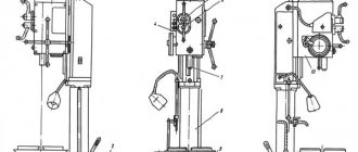
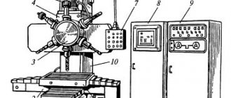
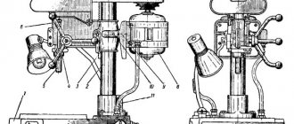
Location of the main parts of the drilling machine 2N135
Location of the main components of the drilling machine 2n135
Designation of the main parts of the drilling machine 2N135
- Drilling machine drive - 2Н135.21.000
- Machine gearbox - 2Н135.20.000
- Piston oil pump - 2N125.24.000 for machine 2N125
- Piston oil pump - 2N135.24.000
- Feed box - 2Н135.30.000
- Column, table, slab - 2N135.10.000
- Speed and feed control mechanism - 2Н135.25.000
- Electrical cabinet - 2N125.72.000
- Electrical equipment - 2N135.94.000
- Spindle assembly - 2Н135.50.000
- Machine cooling system - 2N135.80.000
- Drilling head - 2Н135.40.000
Column, table, stove. The machine column is a cast iron. The drill head and table are manually moved along dovetail column guides. The machine table has three T-shaped slots. An electric pump is installed on the foundation slab, and inside the slab there is a reservoir with a sump for coolant.
Design features
The design of the drilling machine consists of:
- The working head, which serves to secure the tool.
- Drive unit.
- Plunger type oil pump.
- Cooling system for the treated area.
- Spindle.
- Gearbox.
- Unit power supply system, electrical cabinet for connecting to the network.
- Gearbox.
- Speed and feed control system.
- Base plate, column, work table.
The unit frame is made in the form of a monolithic, massive, cast-iron structure. The position of the productive surface is carried out by the operator on the supporting column manually, by pressing the locking device and turning the steering wheel, which performs the function of adjusting the position of the spindle. To move the table surface, special guide grooves are made on the column.
The base plate is also cast iron. It has a hollow structure, inside of which there is a container for storing cooling liquid. There is also a settling tank for large metal contaminants and a filtration device. On the support column itself there is an electric pump with a power of 120 W, which is responsible for supplying the liquid. The coolant is supplied through a system of tubes of various diameters, which supply water directly to the drilling element.
The power unit of the machine is located on the top of the body. The spindle block and gearbox of the machine are located in the housing. The kinematic diagram of the equipment has a simple design solution, in which the power unit and the speed box are connected by a straight shaft. Mechanical speed adjustment is carried out using a handle located on the front side of the drilling head. Speed adjustment is done manually. The box transmits spindle rotation speed at twelve frequencies.
The operating elements of the unit are lubricated using a plunger pump in automatic mode. The operator will only need to monitor the oil level using the sensor located on the front panel.
This model has a manual spindle feed system. This system includes:
- A steering wheel that performs an adjustment function.
- Worm-like transmission.
- Overrunning ratchet and dog clutch.
- Limba.
- Shaft, horizontal, with rack and pinion gear.
Location of controls for drilling machine 2N135
Location of controls for drilling machine 2n135
List of controls for drilling machine 2N135
- Table - “Filling”
- Sign - "Drain"
- Cooling valve
- Bolts for adjusting the table wedge and drill head
- Handle for moving the table and drilling head
- Table clamp and drill head screws
- Sign - “Grounding”
- Input switch
- Label - “Main Switch”
- Signal button MACHINE ON
- Right spindle rotation button
- Spindle left rotation button
- Button for turning on the swinging movement of the spindle when switching speeds and feeds
- Gear shift knob
- STOP button
- Table - “Rotation speed”
- Sign - “Change speed only when stopping”
- Table clamp and drill head screws
- Bolts for adjusting the table wedge and drill head
- Table - “Feed, mm per revolution”
- Feed shift knob
- Manual feed button
- Feed wheel
- Limb for counting the processing depth
- Light switch
- Label - “Cooling”
- Cooling pump switch
- Cam for adjusting the processing depth
- Cam for adjusting the depth of the thread being cut
- Lever for automatic reversal of the main drive when the specified depth of the thread being cut is reached
- Lever to turn off the mechanical feed when the specified processing depth is reached
- Square for manual movement of the drill head
List of graphic symbols indicated on the plates of the 2N135 drilling machine
List of graphic symbols on the plates of the drilling machine 2n135
Operating procedure of the drilling machine 2N135
Mechanical spindle feed
Setting up the machine for normal operation with a mechanical spindle feed consists of installing the table and drilling head in the positions required for operation, clamping them on the column, and setting the required rotation speeds and spindle feeds.
When setting up the machine to operate with manual spindle feed, the knurled cap located in the center of the cross steering wheel should be pressed away from you until it stops.
Turning off the spindle feed at a given depth
When setting up work with turning off the spindle feed at a given depth, the following sequence must be observed:
- install the tool in the spindle;
- secure the workpiece on the table;
- lower the spindle until the tool stops in the part;
- Use a screw to press out and install the dial of the drilling head so that opposite the pointer there is a number corresponding to the depth of processing, taking into account the sharpening angle of the tool.
- Secure the dial. Secure the cam with the letter “P” so that its mark coincides with the corresponding mark on the dial.
After turning on the rotation and feed of the spindle, processing of the part begins. When the desired machining depth is reached, the spindle feed will stop and the spindle will continue to rotate. To stop it, you need to press the STOP button.
Setting up a machine for thread cutting
When setting up a machine for thread cutting with spindle reversal at a certain depth, the following sequence must be observed:
- install the chuck with the tap in the spindle;
- install the workpiece on the machine table;
- lower the spindle until the tool stops in the part;
- Set the dial on the drilling head so that opposite the pointer there is a number corresponding to the processing depth. Align the cam mark “P” with the corresponding mark on the dial and secure the cam.
- Turn off mechanical feed. After turning on the spindle, manually insert the tap into the hole. After 2-3 spindle revolutions, there is no need for manual feed.
- When the specified cutting depth is reached, the spindle is automatically reversed and the tap exits the hole. In order for the spindle to resume right rotation, you need to press the corresponding button.
After installation, lubrication and connection of the machine to the electrical network, no additional adjustments are required. During operation, the initial adjustment may be disrupted.
Operating instructions
The safety clutch of the feed mechanism is adjusted according to the axial force on the spindle by 15% more than the permissible one. To adjust the coupling, it is necessary to remove the right upper cover of the drilling head and use the nut on the worm to decrease or increase the spring tension.
The table guides are adjusted by screws on the right side of the table. The table is clamped using a square screw located on the right side of the table and a table lifting handle.
The guides of the drilling head are adjusted with screws located on the right side surface of the guides; the head itself is clamped with a screw with a square on the same side using the table lift handle.
To tighten the counterweight spring, you need to unscrew the plug at the bottom of the drilling head, drain the oil from the reservoir, and turn the screw to tighten the spring.
For the convenience of clamping the workpiece in the machine vice supplied with the machine, you can use handle 5 (see Fig. 4).
Operating principle
Operation of the machine in operating mode occurs according to the following principle. The workpiece to be processed must be installed and securely fixed on the working surface of the coordinate table. The spindle with the installed tool should be located in the lowest position. Using the worktable longitudinal displacement system, the spindle must be centered.
Then you need to make sure that the end of the part to be processed and the spindle are coaxially positioned. Based on the kinematic possibilities, in the high-speed gearbox we select the rotation speed suitable for processing. We turn on the vertical electric motor of the main drive.
After setting up the kinematic diagram, the tool head moves to the end of the workpiece, and the desired technological operation is performed.
Kinematic diagram of the drilling machine 2N135
Kinematic diagram of the drilling machine 2n135
Bearing layout for drilling machine 2n135
Holzman models
Holzman is a Ukrainian brand. This company recently started producing drilling machines, so it doesn’t offer a wide range. In general, most models have standard characteristics and do not stand out in any way. Among the disadvantages, we can note the high cost of the machines. The spindles in the devices are of high quality, and there are no complaints about them. However, operating the mechanism is quite uncomfortable. This is primarily due to the machine table. Its inclination is extremely small, so it is not possible to work with many parts. In total, the manufacturer provides only 3 stages of automatic feeding. Otherwise, the characteristics of the machines are normal.
Description of the main components of the drilling machine 2N135
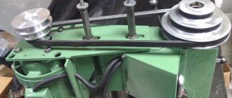
Drilling machine gearbox 2N135
Drawing of the gearbox of the drilling machine 2n135
Gearbox and drive. The gearbox communicates to the spindle 12 different rotation speeds using movable blocks 5 (Fig. 7), 7, 8. The gearbox shaft supports are placed in two plates - upper and lower 4, fastened together by four ties 6. The gearbox is driven into rotation by a vertically located by an electric motor through an elastic coupling 10 and a gear 9. The last shaft 2 of the box - the sleeve - has a splined hole through which rotation is transmitted.
Through gear pair 3, rotation is transmitted to the feed box.
The gearbox, as well as all assembly units of the drilling head, is lubricated from a plunger pump mounted on the lower plate 4. The operation of the pump is controlled by a special oil indicator on the frontal part of the sub-motor plate.
Mechanism for controlling speeds and feeds of drilling machine 2N135
Remote control for speeds and feeds of drilling machine 2n135
Mechanism for switching speeds and feeds of a drilling machine 2N135
Mechanism for switching speeds and feeds of a drilling machine 2n135
Mechanism for switching speeds and feeds . The gears are switched by handle 2 (Fig. 8), which has four positions around the circumference and three along the axis, the feeds are switched by handle 3, which has three positions along the circumference for machines of models 2N135 and four for 2N150, and three positions along the axis. The handles are located on the front side of the drilling head. The countdown of switched on speeds and feeds is carried out according to plates 1 and 4.
Feed box for drilling machine 2N135
Drawing of the feed box of the drilling machine 2n135
Gearbox. The mechanism is mounted in a separate housing and installed in the drilling head. By moving two triple gear blocks, nine different feeds are carried out on the 2N125, 2N135 machines and twelve feeds on the 2N150 machine. On the 2N125 and 2N135 machines, the feed boxes differ only in the drive, which consists of gears 1 on the 2N125 machine (Fig. 9), and on gears 2, 3 on the 2N125, 2N135 machines, respectively. The feed box is mounted in the bore of the upper support of the worm of the feed mechanism. On the last shaft of the box there is a clutch 4, which transmits rotation to the worm.
Drilling head of machine 2N135
Drawing of the drilling head of the drilling machine 2n135
The drilling head is a box-section casting in which all the main assembly units of the machine are mounted: speed box, feed box, spindle, feed mechanism, spindle counterweight and speed and feed switching mechanism.
The feed mechanism , consisting of a worm gear, a horizontal shaft with a rack and pinion gear, a dial, cam and ratchet overrunning clutches, and a steering wheel, is an integral part of the drilling head.
The feed mechanism is driven from the feed box and is designed to perform the following operations:
- manually bringing the tool to the part;
- turning on the working feed;
- manual feed advance;
- turning off the working feed;
- manual spindle retraction upward;
- manual feed used in thread cutting.
The principle of operation of the feed mechanism is as follows: when the steering wheel 14 (Fig. 10) rotates, the cam clutch 8 turns toward itself, which, through the half-coupling cage 7, rotates the rack and pinion gear shaft 3, and the spindle is fed manually. When the tool approaches the part, a torque arises on the gear shaft 3, which cannot be transmitted by the teeth of the cam coupling 8, and the half-coupling cage 7 moves along the shaft until the ends of the cams of parts 7 and 8 are facing each other. At this moment, the cam clutch 8 rotates relative to the gear shaft 3 at an angle of 20°, which is limited by a groove in part 8 and a pin 10. On the holder - half-coupling 7 sits a double-sided ratchet disk 6, connected to the half-coupling by pawls 13. When moving the holder-half-coupling 7 the teeth of the disk 6 engage with the teeth of the disk, which is integral with the worm wheel 5. As a result, rotation from the worm is transmitted to the rack and pinion gear and the spindle is mechanically fed. With further rotation of the steering wheel 14 with the feed switched on, the pawls 13, sitting in the half-coupling cage 7, slip over the teeth of the inner side of the disk 6; There is a manual advance of the mechanical feed.
When the feed is manually turned on by the steering wheel 14 (after turning it towards itself at an angle of 20°), the tooth of the coupling 8 stands against the cavity of the half-coupling cage 7. Due to the axial force and the special spring 12, the half-coupling cage 7 moves to the right and disengages the toothed disks 5 and 6; mechanical feed stops.
The feed mechanism allows manual spindle feed. To do this, it is necessary to turn off the mechanical feed with the steering wheel 14 and move the cap 9 along the axis of the gear shaft 3 away from you. In this case, pin II transmits torque from the cam clutch 8 to the horizontal shaft. A dial 4 is mounted on the left wall of the drilling head for visually measuring the processing depth and adjusting the cams.
To manually move the drilling head along the column guides, there is a mechanism that consists of a worm pair 2 and a rack pair I. To protect the feed mechanism from breakage, there is a safety clutch 15. A nut 16 and a screw 17 are used to regulate the spring counterweight.
Operating principle
Operation of the machine in operating mode occurs according to the following principle. The workpiece to be processed must be installed and securely fixed on the working surface of the coordinate table. The spindle with the installed tool should be located in the lowest position. Using the worktable longitudinal displacement system, the spindle must be centered.
Then you need to make sure that the end of the part to be processed and the spindle are coaxially positioned. Based on the kinematic possibilities, in the high-speed gearbox we select the rotation speed suitable for processing. We turn on the vertical electric motor of the main drive.
After setting up the kinematic diagram, the tool head moves to the end of the workpiece, and the desired technological operation is performed.
Adjusting the drilling machine 2N135
Spindle assembly for vertical drilling machine 2N135
Drawing of spindle assembly for drilling machine 2n135
Spindle 2 (Fig. 11) is mounted on 4 ball bearings. The axial feed force is perceived by the lower thrust bearing, and the tool knockout force is perceived by the upper one. The bearings are located in sleeve 3, which moves along the axis using a rack and pinion pair. The spindle bearings are adjusted using nut 1.
To knock out the tool, use a special device on the spindle head. Knockout occurs when the spindle is lifted by the steering wheel. The holder of the device rests against the body of the drilling head, and the lever 4 rotates around its axis; knocks out the tool.
The spindle of the drilling machine 2n135 is mounted on 4 bearings:
- 20. Upper bearing No. 6-7000110 , single-row radial ball, 80x80x10 mm, 6th accuracy class
- 21. Bearing No. 5-8110 , thrust ball, 50x76x14 mm, 5th accuracy class
- 24. Bearing No. 5-8210 , thrust ball, 50x76x22 mm, 5th accuracy class
- 25. Lower bearing No. 5-110 , single-row radial ball, 50x80x16 mm, 5 accuracy class
Adjusting the drilling head of the 2N135 machine
When assembling the machine during the repair process, it is necessary to observe conditions that affect the accuracy of its operation.
Thus, the gap between the guide bushings of the drill head and the quill of the spindle assembly should be no more than 0.01 mm.
When installing the drilling head and table on the column guides, the 0.03 mm probe should not pass into the joint, and all the requirements of GOST 7599-73 section 4 must be met.
The spindle thrust bearings are also subject to adjustment .
To adjust the spindle thrust bearing you must:
- unscrew the plug on the front part of the drilling head of the 2N125 machine or the cover on 2N135 and 2N150;
- install the spindle so that the stopper in the nut is aligned with the hole;
- release the stopper and, turning the spindle, align the hole in the nut with the hole in the drilling head;
- Having inserted a cylindrical rod into the hole of the nut, turn the spindle counterclockwise until the axial play is eliminated and tighten the nut stopper.
Technical characteristics of bearing No. 110
Bearing No. 110 - single-row radial ball, 50x80x16 mm
Along with the open bearing 110, closed bearings 80110 (metal washers), 180110 (oil-resistant rubber) and 60110 (closed with a metal washer on one side) are produced. The products, closed on both sides, have a lubricant inside, which is added at the factory, and its type is coded in an additional symbol to the right of the number (for example, C17 - lithol). They do not need care. There is also a bearing 50110 - it has a locking groove on the outer ring.
The main domestic manufacturers are SPZ-4 (Samara, assembled from Chinese components), 23 (Vologda, or VBF) bearing factories, while truly high-quality products are produced in Vologda. In the past, the product was produced by 4 GPPs, including those of high accuracy classes (now it is the Aircraft Bearings Plant, but this type is not currently produced). In addition, there may be products with the mark 18 GPZ (Vinitsa), they are sold from storage, and while open modifications are still acceptable to use, it is not recommended to buy closed ones due to thickened lubricant. Designations not mentioned here most likely indicate that the bearing is Chinese.
The approximate price of high-quality bearings is about 120 - 140 rubles (closed ones are slightly more expensive), Chinese ones - 50 - 60.
The imported analogue has the number 6010 (Z, ZZ or 2RS are designations of closed types). The cost of imported bearings greatly depends on the brand. Thus, the main modifications of the Swedish company SKF or the German FAG have a price of up to 1000 rubles, and “budget” brands, for example, FBJ - 160 - 170 rubles.
Dimensions and characteristics of bearing 110 (60110, 50110, 80110, 180110, 6010)
- Inner diameter (d): – 50 mm;
- Outer diameter (D): – 80 mm;
- Width (height) (H): – 16 mm;
- Weight: – 0.26 kg;
- Ball diameter: – 8.731 mm;
- Number of balls in the bearing: – 13 pcs.;
- Dynamic load capacity: – 21.6 kN;
- Rated speed: – 5000 rpm.
Diagram of bearing 110 of drilling machine 2n135
Technical characteristics of bearing No. 8210
Bearing 8210 is a single-row thrust ball bearing consisting of three parts - two rings (the diameter of one of them is 1 mm less than the one that is mounted directly on the shaft) and a cage on which the rolling elements are located.
Used in industrial equipment in units with axial load. The bearing is a thrust bearing of the basic design, with one row of rolling elements. The main type of load for which it is designed is axial. In the event of radial or slight misalignment of the shafts, the service life of the bearing is greatly reduced. The load must be constant, because otherwise the balls slide “idlely” along the rolling tracks and become very hot.
This type is consumed in large quantities at various oil refineries and organic synthesis enterprises. As for its use in special and automotive equipment, most of the common models are no longer used, and therefore few bearing sellers keep it in warehouses.
The main manufacturer in Soviet times was the Kursk Bearing Plant. Now the type is produced at GPZ-2 (Moscow), SPZ-4 (Samara)
The imported name of the bearing 8210 is 51210 (also marked on 2 GPZ).
Dimensions and characteristics of bearing 8210 (51210)
- Inner diameter (d): – 50 mm;
- Outer diameter (D): – 78 mm;
- Width (height) (H): – 22 mm;
- Weight: – 0.385 kg;
- Ball diameter: – 11.112 mm;
- Number of balls in the bearing: – 17 pcs.;
- Dynamic load capacity: – 49.4 kN;
- Rated rotation speed: – 2400 rpm.
Diagram of bearing 8210 (51210) of drilling machine 2n135
Photo of bearing 8210 (51210)
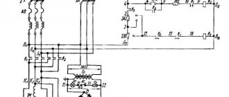
Electrical equipment and electrical circuit of the drilling machine 2N135
Electrical diagram of drilling machine 2n135
List of elements for the electrical circuit of the drilling machine 2n135
The electrical circuit diagram is the same for the entire series of machines 2n125, 2n135, 2n150. However, the components included in the electrical circuit have different parameters due to the fact that the models have main engines of different power (2n125 - 2.2 kW, 2n135 - 4.0 kW, 2n150 - 7.5 kW)
Thus, all elements of the electrical circuit associated with the main engines have different parameters on different machine models, see Table 2.
Variable data table for the electrical circuit of the drilling machine 2n135
Brief characteristics of electrical equipment
The electrical equipment of the machines includes a three-phase squirrel-cage asynchronous electric motor for rotation and working feed of the spindle, an electric cooling pump, and electrical control equipment.
The AC voltage values can be as follows:
- power circuit 3 ~ 50 Hz, 220, 380, 400, 415, 440 and 500 V;
- control circuit ~ 110 V;
- local lighting circuit ~ 24 V;
- alarm circuit ~ 5 V.
The power circuit voltage is determined by the customer.
Description of the operation of the electrical circuit of the machine
Initial Startup Information
During the initial start-up of the machine, it is necessary to free the magnetic starters from the wedges, check the reliability of the clamping of wires and grounding, and the integrity of the installation of electrical equipment by external inspection.
After inspection in the electrical control cabinet of the incoming automatic machine Q1, connect the machine to the workshop network, using buttons and switches, check the clear operation of the magnetic starters and relays, and the correct direction of rotation of the electric motor M1. The check must be done at idle speed.
Description of operating modes
By turning on the input circuit breaker Q1, voltage is supplied to the main and auxiliary circuits, and the H2 signal lamp on the remote control lights up. If cooling and lighting are required, the corresponding switches are placed in the ON position.
By pressing the S2 RIGHT button, the starter coil K1 receives power, the main contacts turn on the electric motor Ml for right rotation of the spindle. Through the block contacts K1, the starter K2 is turned on, which turns on the electric motor M2 and the delay relay K7.
When you press the S3 LEFT button, the starter K1, the electric motor Ml, and the relay K7 are turned off. After the discharge of capacitor C3, the contacts of relay K7 (28-26) close, and the starter K3 and the electric motor Ml are turned on for left-hand rotation of the spindle. Relay K7 turns on again.
With automatic reverse, these switches occur when microswitch S6 is activated from a cam mounted on the dial.
Stopping is carried out by pressing the S1 STOP button. In this case, starters K1 or K3, K2 are turned off, turning off electric motors M1, M2. Through relay contacts K7 (7-9), relay K6 is turned on, followed by starters K4 and K5. The windings of the electric motor Ml are connected via rectifier VI, V2 to transformer T1. Electrodynamic braking of the spindle occurs.
After the discharge of capacitors C1, C2, relay K6 is turned off, turning off starters K4, K5.
When switching speeds, if the gears do not engage, the rocking motion of the engine rotor Ml is used. By pressing the S4 ROCKING MOTION button, starter K4 is turned on, supplying reduced rectified voltage through phases IC2-IC3.
Through resistance R2, relay K6 is turned on with a delay, turning off starter K4 and turning on starter K5. In this case, the reduced voltage flows through the phases ICI-IC2. Such switchings provide swinging of the rotor, which makes it easier to change gears.
Instructions for using electrical equipment
It is necessary to periodically check the condition of the starting and relay equipment. Contacts of electrical devices must be cleaned of dust, dirt and carbon deposits.
When inspecting relay equipment, special attention should be paid to the reliability of the closing and opening of contact bridges.
The frequency of technical inspections of engines is set depending on production conditions, but not less than once every two months.
Information about interlocks, alarm system, protection and grounding
The input circuit breaker is equipped with a special lock that locks the input switch in the off state.
When the input switch is turned on, a special lamp with a white lens lights up on the remote control. Protection against short circuit currents is provided by a circuit breaker and fuses.
Overload protection of motors Ml, M2 is provided by thermal relays. Zero protection is provided by coils and contacts of electromagnetic starters.
The machine must be securely connected to the workshop grounding device.
From the grounding terminals of the electrical cabinet, protective circuits are routed to the motor housings and the control panel.
Drilling equipment
In the machine park, a large percentage is occupied by the segment of drilling machines. This is explained by the need to carry out drilling in almost any technological process. All the necessary information related to the design of the unit is contained in the passport supplied with any model of the unit.
All equipment in this segment consists of three groups, each of which is distinguished depending on the specifics of the work:
- special;
- specialized;
- universal.
In each of these groups, gradation can be made depending on the size of the drill, and, accordingly, the holes that a given drilling machine can handle. Let's highlight the main ones:
- light, up to 12 mm;
- medium, 18-50 mm;
- heavy, over 50 mm.
This is interesting: Presses for squeezing juice from apples, grapes, fruits and berries: types, making your own
Techniques for drilling difficult-to-cut alloys
Difficult-to-process alloys include heat-resistant, titanium, stainless steels, etc. When drilling them with a standard drill, highly deformed strip chips are formed, wedged in the grooves of the drill, causing the occurrence of large cutting forces. This entails an increase in drill vibrations, which has a detrimental effect on the condition of its cutting edges, which quickly become dull. Therefore, difficult-to-cut alloys should be drilled taking into account the following recommendations:
- 1. Use special shortened (compared to standard) drills, the length of which should not exceed their diameter by more than 4-5 times.
- 2. Do not use drills that have been shortened as a result of regrinding standard drills. Shortening a standard drill results in an increase in the length of the transverse cutting edge due to the fact that the thickness of the bridge increases as it approaches the shank.
- 3. In the absence of special shortened drills, it is possible to put on and fasten rigid split bushings with an internal diameter equal to the diameter of the drill and an external diameter equal to 35..60 mm onto standard drills. The bushing must be secured close to the end of the chuck or machine spindle. The length of the sleeve depends on the length of the drill, but it is desirable that the part of the drill protruding from the sleeve does not exceed the diameter of the drill by more than 5..6 times.
- 4. To increase the durability of the drill, the width of its guide strips should be reduced to 0.2..0.4 mm, the clearance angle should be increased to 12° and double sharpening should be used.
- 5. To prevent jamming of chips, chip separating grooves should be cut on the rear surface of the drill (Fig. 86), dividing the chips widthwise into several parts; this improves the conditions for its removal from the hole.
- 6. To prevent chips from wrapping around the drill when leaving the hole, use a special chip breaker, which is a conical cap attached to the drill. The shavings, resting against the cap, break into short spirals.
- 7. Drilling should be carried out only with the use of cutting fluids. For heat-resistant alloys, a 50% emulsion or aqueous solution of barium chloride with the addition of 1% sodium nitrate is recommended; for titanium alloys, castor and sulfur oils, oleic acid or mixtures thereof are recommended.
Technical characteristics of the machine 2N135
| Parameter name | 2N125 | 2N135 | 2N150 |
| Basic machine parameters | |||
| The largest drilling diameter in steel is 45, mm | 25 | 35 | 50 |
| The smallest and largest distance from the end of the spindle to the table, mm | 60…700 | 30…750 | 0…800 |
| The smallest and largest distance from the end of the spindle to the plate, mm | 690…1060 | 700…1120 | 700…1250 |
| Distance from the axis of the vertical spindle to the rack guides (overhang), mm | 250 | 300 | 350 |
| Desktop | |||
| Maximum load on the table (center), kg | |||
| Dimensions of the working surface of the table, mm | 400 x 450 | 450 x 500 | 500 x 560 |
| Number of T-slots Dimensions of T-slots | 3 | 3 | 3 |
| Maximum vertical movement of the table (Z axis), mm | 270 | 300 | 360 |
| Table movement per one revolution of the handle, mm | |||
| Spindle | |||
| Maximum movement (installation) of the spindle head, mm | 170 | 170 | 250 |
| Maximum movement (stroke) of the spindle, mm | 200 | 250 | 300 |
| Spindle movement by one dial division, mm | 1,0 | 1,0 | 1,0 |
| Spindle movement per one revolution of the handwheel-handle, mm | 122,46 | 122,46 | 131,68 |
| Spindle speed, rpm | 45…2000 | 31,5…1400 | 22,4…1000 |
| Number of spindle speeds | 12 | 12 | 12 |
| Maximum permissible torque, Nm | 250 | 400 | 800 |
| Spindle taper | Morse 3 | Morse 4 | Morse 5 |
| Machine mechanics | |||
| Number of working feed stages | 9 | 9 | 12 |
| Limits of vertical working feeds per spindle revolution, mm | 0,1…1,6 | 0,1…1,6 | 0,05…2,24 |
| Cycle management | Manual | Manual | Manual |
| Maximum permissible feed force, kN | 9 | 15 | 23,5 |
| Dynamic spindle braking | Eat | Eat | Eat |
| Drive unit | |||
| Main motion drive electric motor, kW | 2,2 | 4,0 | 7,5 |
| Electric coolant pump Type | X14-22M | X14-22M | X14-22M |
| Machine dimensions | |||
| Machine dimensions, mm | 2350 x 785 x 915 | 2535 x 825 x 1030 | 2930 x 890 x 1355 |
| Machine weight, kg | 880 | 1200 | 1870 |
- Universal vertical drilling machines 2N125, 2N135, 2N150. Operating manual 2N125.00.000 RE, 1987
- Barun V.A. Working on drilling machines, 1963
- Vinnikov I.Z., Frenkel M.I. Driller, 1971
- Vinnikov I.Z. Drilling machines and work on them, 1988
- Loskutov V.V Drilling and boring machines, 1981
- Panov F.S. Working on CNC machines, 1984
- Popov V.M., Gladilina I.I. Driller, 1958
- Sysoev V.I. Handbook for a Young Driller, 1962
- Tepinkichiev V.K. Metal cutting machines, 1973
Bibliography:
Related Links. Additional Information
- Classification and main characteristics of drilling-milling-boring group of machines
- Selecting the right metalworking machine
- Machine repair technology
- Methodology for checking and testing drilling machines for accuracy and rigidity
- Directory of drilling machines
- Manufacturers of drilling machines in Russia
Home About the company News Articles Price list Contacts Reference information Interesting video KPO woodworking machines Manufacturers
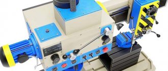
Device design and features
The device of this type of unit includes the following elements:
- spindle;
- gearbox;
- base, workplace and column;
- drive unit;
- head for securing the tool;
- electrical cabinet;
- cooling system;
- gearbox;
- system that controls speeds and feeds;
- plunger oil pump.
The technical characteristics of vertical drilling machines indicate their versatility. These devices can perform not only drilling, but also countersinking, reaming, threading and reaming of holes.
This is due to the use of durable and hard tools made from well-cutting steels.
The ability to cut threads with machine taps is ensured by the reversibility of the spindle, thanks to which it can move in both directions.
The main features of the device are as follows:
- machine weight - 1199 kg;
- spindle torque can reach a maximum of 399 Nm;
- presence of a spindle stop system;
- the maximum permissible force at which the feed is performed is 15 kN;
- the use of an electric pump of the X14-22M type as part of the structure to transfer the cooling liquid to the processing site;
- The dimensions of the desktop are 449*499 mm, on the surface of which there are three grooves in the shape of the letter “T”.
One of the main technological features of the machine is its 100% manual control. All stages of work are adjusted manually, and the spindle feed is carried out mechanically.
General characteristics of the unit include three large parts:
- workplace-table on which the part to be processed is located;
- stable cast iron frame with space inside for electrical equipment;
- a drilling head with a spindle that moves vertically using a worm shaft.