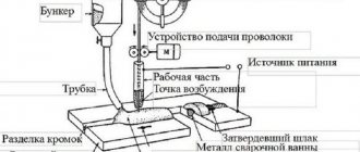
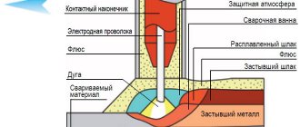
Electrode release
Distance from the torch nozzle to the end of the welding wire. As output increases, gas protection of the welding zone deteriorates. With a small output, the welding technique becomes more complicated, especially corner and T-joints.
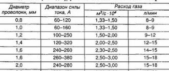
Reach and release depend on the diameter of the electrode wire:
| Wire diameter, mm | 0,5-0,8 | 1-1,4 | 1,6-2 | 2,5-3 |
| Electrode extension, mm | 7-10 | 8-15 | 15-25 | 18-30 |
| Electrode outlet, mm | 7-10 | 7-14 | 14-20 | 16-20 |
| Gas consumption, l/min | 5-8 | 8-16 | 15-20 | 20-30 |
The optimal set of mode parameters makes the process stable at three stages:
1 - when the arc is ignited and the welding operating mode is established; 2 - in a wide range of operating modes; 3 - during the completion of welding.
The welding process is considered stable if its electrical and thermal characteristics do not change over time or change according to a specific program. In this regard, mechanized welding in shielding gases is carried out with a stationary arc, pulse-arc method, with a synergetic control system.
Normative documents. How to use
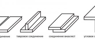
According to GOST 5264-80 for manual arc welding, the entire variety of welded joints can be classified into four main types (the abbreviated designation in Russian capital letters is given in parentheses):
- Butt (C);
- Angular (U);
- T-bar (T);
- Lap seams (H)
An example of an abbreviated entry for the type of connection and its number in order: T1, C17, etc.
Also indicates the main dimensions of the weld. For example, on a butt weld, the parameter “e” is the width; “g” - convexity, or reinforcement of the seam.
For fillet (or T) welds, the letter “k” denotes the leg.
According to the European standard EN ISO 2553-2013 “Joints by welding and soldering,” the letter “a” indicates the thickness of the seam; “z” – seam leg; “S” – penetration depth. When designated according to the European standard, the letters z, a, S are present in the drawings, so it is important to know this.
It also gives us an idea of what the gap between the parts should be, how to properly prepare the edges, what possible geometry of the edges is possible when welding on one or both sides, with a backing under the root of the seam, etc.
According to the European standard, the requirements for the preparation of parts for welding are determined according to EN ISO 9692-1:2003 “Welding and similar processes - recommendations for the preparation of joints”
If a novice welder is faced with the task of welding two plates, then the most asked questions are as follows:
- what diameter or type of electrode should I take?
- what current to cook with?
- how to set the gap between the parts?
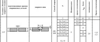
What do the standards recommend for us regarding clearances? According to GOST 5264-80, for example, for a three-millimeter plate, the edges will be straight with a gap between the parts of 0-2 mm. Seam reinforcement is offered in the range from 0.5 to 2.5 mm, and the seam width is no more than 7 mm.
According to EN ISO 9692, for one-sided welding of a 3 mm thick plate, it is recommended to prepare edges with a straight bevel and a gap between the parts of approximately 3 mm. Weld convexity parameters are determined according to ISO 5817:2009.
When welding an 8 mm plate on one side, GOST 5264-80 recommends making a V-shaped bevel of the edges at an angle of 22 -27 degrees with a blunting of the edges of 0-2 mm and a gap of 0-3 mm.
According to EN ISO 9692, for the same plate 8 mm thick and one-sided welding, the opening angle of the edges is selected ? = 40-60 degrees, the gap between the parts is 0-4 mm, the bluntness is 0-2 mm.
As you can see, both in GOST and in European standards there are no hard numbers, there are size ranges. The welder decides which gap or blunting of edges to choose, based on the brand and diameter of the electrode, the spatial orientation of the seam, the welding current and his skill.
Go to menu
Stationary arc welding
Random fluctuations in the electrode wire feed speed and arc length can disrupt the stability of the process and lead to short circuits. arc breakage. To avoid this, it is necessary to change the melting rate of the electrode, i.e. Vary the welding current accordingly.
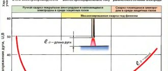
The current-voltage characteristic of the arc (volt-ampere characteristic of the arc) in protective gases with a consumable electrode has an increasing character.
At a certain point in the stable welding process, the electrode wire feed speed Vп1 is equal to the melting speed Vpl1. In this case, the current and voltage parameters were determined by the operating point A1 with arc length ld1. Let us assume that due to malfunctions in the wire feed mechanism, the feed speed has decreased. Then a relative melting rate ΔVmel = Vmel1 - Vп2 arises, which leads to the movement of the operating point to a new position - A2. It is characterized by a decrease in welding current (Δl), which leads to a decrease in the initial melting rate. The welding process returned to point A1 with arc length ld1. This process is called self-regulation along the arc length. It becomes more intense with a more rigid voltage-ampere characteristic of the power source.
When welding from a source with a rigid characteristic, the welder adjusts the current mode by adjusting the wire feed speed. However, this changes the length of the arc and the voltage on it. To maintain the required arc length, when setting the mode, you should adjust the current-voltage characteristic of the power supply, moving from one (I) to another (II).
The stability of the arc, especially in the ceiling position, as well as the size of the weld and its quality depend on the type of transfer of electrode metal through the arc gap. There are three types of transfer.
1. Large droplet transfer with arc short circuits. Droplets are formed 1.5 times larger than the diameter of the electrode wire. The process is accompanied by short circuits with a natural pulse-arc process determined by the mode parameters. The voltage on the arc periodically decreases to 0 and at the moment of drop separation it increases to the operating value. The current at the moment of a short circuit increases, which leads to the detachment of a drop of electrode metal.
The process proceeds with metal spattering, which worsens the appearance of the welded joint, leading to lack of penetration and excessive convexity of the seam.
2. Medium drop transfer without short circuits.
The arc burns continuously, and the electrode metal is transferred through the arc in droplets whose diameter is close to the diameter of the wire.
Welding occurs with periodic changes in arc voltage and welding current.
The pulse-arc process depends on the parameters of the welding mode and is also accompanied by spattering, which reduces the quality of the weld.
3. Jet transfer.
The arc burns continuously, the melted end of the electrode is extended into a cone, from which drops measuring less than 2/3 of the electrode diameter flow into the weld pool. The mass of the drop is small, so the electrode metal is easily transferred to the pool during welding in all spatial positions.
Spattering during jet transfer is negligible. Productivity is high. Jet transfer can be obtained in argon. In carbon dioxide, this transfer is achieved at high welding current densities or with wires activated by rare earth elements
Controlled transfer of electrode metal with the required droplet sizes is successfully achieved using a pulsed-arc process, when the arc voltage and welding current are periodically changed.
How to hold a short arc?
As has already become clear, in order to maintain a stable short arc length, you need to constantly move the electrode forward as it burns.
“Feed” it evenly to the weld pool.
The easiest way to hold a short arc, which by the way is recommended by technologists, is to rest one edge of the electrode (visor) on the surface of the weld pool.
All comes with experience
, because in ordinary life this movement is rarely used, however, in order to achieve it,
you need to remember about frequent mistakes
, which greatly interfere with maintaining a stable arc length.
Mistake number one: fear.
Remembering myself at the beginning of learning welding, moments of wild fear of the process itself clearly pop up in my head. I constantly felt like I was about to be electrocuted or painfully burned by sparks or molten metal.
In order to prevent this, you should simply take care of your clothing
and gloves
- cover all exposed skin and do not worry about sparks, which, if they hit your skin, will make you flinch and throw off the held arc.
Mistake number two: stability
Perhaps the most important criterion for maintaining an even arc length is a stable position of your entire body when welding.
Be sure to take the most comfortable and stable position before welding, run the entire distance with the electrode idle
to make sure your body position is correct.
Hold the handle of the electrode holder with both hands - hold it with one and support it with the other.
If there is a support in front of you, be sure to place the elbow of the hand that is holding your other hand on it.
Wrap the cable around your hand
so that it does not dangle freely in space, does not sway and cannot touch foreign objects.
When welding while standing, it is better not to place your legs narrowly, but to spread them for greater stability.
Pulse arc welding
Pulse-arc (non-stationary arc) welding using the MIG/MAG method is possible with low welding current in all spatial positions of the seam with minimal spatter and high-quality seam formation.
There are two main types of electrode metal transfer:
- with continuous arc burning - “long arc”;
- with short circuits of the arc gap - “short arc”
The peculiarity of pulsed-arc welding with a consumable electrode is that the process of transfer of electrode metal can be controlled. When welding with a “long arc”, two types of transfer are possible:
- one pulse - one drop;
- one pulse - a few drops.
Short arc transfer is typical for carbon dioxide welding. Instability and increased spattering of the electrode metal are determined by the properties of the power source and depend on the nature of the change in instantaneous power both during the arcing period and during a short circuit.
In pulsed arc welding using the MIG/MAG method, synergistic process control is effective.
Speed
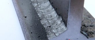
Excessive welding speed leads to the formation of a thread-like seam, the characteristic features of which are a small width and depth of penetration. The slag comes off very hard. At such speeds, a related problem arises - it is very difficult to maintain uniformity of movement.
The photo shows: in the area where the movement speed is higher, the scales are pointed and the seam width is smaller; and where the speed is lower, the scales take on a rounded shape and the width of the seam increases. Such a weld can literally tear off at the slightest load, since the adhesion of the additive to the base metal is very weak.
In very rare cases, for example, when welding in several passes, a thread-like seam is used as a facing seam. This way, you can weld the groove without melting the part.
Go to menu
Synergetic management
Inverter power supplies allow you to accelerate changes in current parameters up to 1000 A/ms. The high speed of the source contributes to the optimal choice of pulse and pause currents, pulse and pause time, pulse frequency depending on the wire feed speed. This ensures stable transfer of a drop of electrode metal in one pulse.
In modern semi-automatic machines, microprocessor technologies have been introduced to control pulsed welding processes, depending on the steel grade, wire diameter, and type of shielding gas. Such systems are called synergetic.
Thanks to the pre-programming of pulse modes, only two parameters are regulated during welding: welding current and arc length . Synergetic equipment easily adjusts welding modes depending on the grade of steel being welded, the diameter of the electrode wire and the type of shielding gas.
In the synergetic equipment system, optimal welding mode parameters are programmed for various material combinations: carbon steel, stainless steel, aluminum alloys; diameters of solid electrode wire: 1.0; 1.2; 1.6 mm; crater filling time.
For each wire diameter there is a wide range of current mode values, which allows you to weld materials of different thicknesses and in all spatial positions. Synergic systems increase productivity by 20% compared to conventional MIG/MAG welding.
General information on the welding arc
From a scientific point of view, a welding arc is characterized by 2 properties - the release of a huge amount of heat and powerful radiation. I attribute the first to the positive side, and the second to the negative.
Materials with electromagnetic properties are usually used as conductors of electrical discharge. From my own experience I was convinced that graphite rods of round cross-section, which in the scientific literature are sometimes called arc lamps, perform best.
1) Occurrence, temperature and exposure
In order to understand how the welding process is carried out, I always advise studying the theoretical basis of physical phenomena. When a voltaic arc is formed, Joule's law manifests itself in all its glory.
Algorithm for the occurrence of an electric arc:
- Contact of electrodes.
- The release of enormous amounts of heat at the joint.
- The ends of the conductors become hot.
- Disconnection of electrodes.
- Release of electrons by the cathode.
- Electrons penetrate the air flow between the electrodes, splitting the molecules into “+” and “-”.
- The occurrence of an electric arc.
- Stabilization process due to an increase in the number of charged particles.
- Education from the cooking bath.
As practice shows, the most common sources for the occurrence of discharges are coated metal rods and the part itself that the welder plans to process.
Important: the arc voltage between metal electrodes is from 17 to 23 V, and if we are talking about carbon electrodes, the average voltage value varies from 40 to 60 V.
When testing the profitability of carbon and metal electrodes, it is easy to notice that the electrical resistance in the second case is much lower than when using carbon materials. This phenomenon is caused by the presence of metal vapors.
For a better understanding of the principles of heat release, I decided to add a small diagram from the reference literature above. It is noticeable from the figure that the temperature regime in different areas of the electrodes differs from each other. Here there is a relationship between the amount of heat generated and the heating level. So at “+” 40% is produced, at “-” 35%, and the remaining 25% of the heat comes directly from the arc itself. To compensate for the temperature difference, it is necessary to take carbon conductors of different thicknesses. On the positive side, the diameter is larger, and on the negative side, it is smaller.
Submerged Welding Technology Overview
2) I tell you what the length of the welding arc is
After the electrode touches the workpiece and an electric arc occurs, it is immediately retracted to a certain distance from the workpiece, thereby forming a length parameter. The end of the rod begins to melt, transferring drops of liquid metal to the seam being welded. The average number of drops per second ranges from 15 to 35, which makes this process similar to laser radiation for the eye.
The arc length is the actual distance from the end of the electrode to the base of the weld crater. There is a direct relationship between the diameter of the rod and the length of the electric arc.
It can be expressed through the formula:
L (arcs) = 1/2*d – 1.2*d, where
L – arc length;
d – value of the diameter of the electrode rod.
To make it easier to master the calculation of a potential arc on various electrodes, I will give a small example.
Calculation example: let us have a rod with a diameter of 5 mm. To calculate the minimum and maximum of the electric arc, we substitute the value into the formula above - 0.5*5=2.5 mm and 1.2*0.5=6 mm. Thus, we obtain values from 2.5 mm to 6 mm along the possible length of the welding arc.
There are 3 types of welding arc based on thickness, but I’ll be honest that in 95% of cases welders use exclusively short ones. Medium and long are used in exceptional situations. I described each type in more detail in the table below.
| Type | View | Description |
| Short | The optimal option, due to which the welder can achieve a standard quality weld. A short arc is distinguished not only by appearance, but also by ear - a dry crackling sound will be heard, similar to heating oil in a frying pan. | |
| Average | The average value is easiest to maintain for new welders. The result will be a seam of average quality. If a person has just started using a welding machine, it is worth starting the practice with the average length of the electric arc. | |
| Long | As a result of working at a large distance from the surface of the seam, its quality will be below average. Negative manifestations are metal oxidation and the formation of an uneven surface of accumulated metal from the electrode. Burns unsteadily with a characteristic hissing sound. |
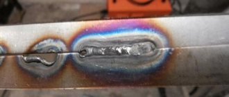
The key disadvantage of a long arc is the splashing of electrode drops over the seam area due to insufficient heating of the area. By external manifestations, even an inexperienced welder will be able to tell where a short and where a long electric arc was used.
The photo I took above makes it clear which type of arc was used where. As they say, quality is obvious. Even with good application skills, the difference between the upper and lower seams is dramatic and noticeable even to the naked eye.
Practical definition
A qualified specialist will easily select the optimal connection mode, regardless of the welding mode, MMA or MIG. Beginners often have to turn to reference books.
Manufacturers of welding equipment and consumables provide their products with operating instructions containing recommendations for choosing a mode . Such information should be considered priority.
When working at production sites, there is no opportunity to study technical literature. To select parameters, simple formulas have been developed that allow you to select indicators in a matter of seconds.
How does an experienced welder choose?
Correct selection of operating parameters depends on the qualifications of the specialist. Special welder tables have been developed for beginners . They indicate all the necessary operating parameters. The reference point is the diameter of the electrode.
An experienced welder does not wonder how to select the current for welding with an inverter or other machine. Let's consider based on what indicators we can select optimal welding indicators.
During the joining of parts, specific chemical and physical processes occur, which are accompanied by characteristic sound and visual effects. These include:
- Stability and intensity of electric arc combustion.
- The size of the melt zone.
- Metal fluidity.
- Crystallization rate.
- Seam shape.
By analyzing the combination of the above factors, a specialist can correctly select, and, if necessary, adjust welding parameters during work.
An important indicator is the size of the cross-section of the filler material , the features of the choice of which will be discussed below.
Dependence on electrode thickness
Technical documentation and training manuals contain tables that allow you to select the optimal type and cross-sectional area of the electrode, depending on the properties of the material being welded.
So, how do you choose the diameter of the electrode depending on the thickness of the metal? Before addressing this issue, it is necessary to study the changes that the surface and filler material undergo with increasing energy. First of all, as the current increases, the thermal effect increases, which accelerates the melting processes of the electrodes and the plane. For example, the optimal current for a 3 mm electrode will be 65-100 A, depending on the type of base metal.
As an example, see the table for selecting the diameter of the electrode for welding.
[stextbox Increasing the cross-section increases the density of the welding arc, which is the ratio of the number of amperes to the contact area. Unit of measurement – A/mm 2.
How to choose the welding current value
First of all, it is necessary to select the type and polarity of the current, which is established based on the chemical composition of the metal and its thickness, as well as the type of coating of the electrodes. The table shows the dependence of the welding current on the diameter of the electrodes:
| Electrode diameter, mm | Minimum current, A | Average current, A | Maximum current, A |
| 1,6 | 25 | 30 | 35 |
| 2,0 | 40 | 50 | 55 |
| 2,5 | 60 | 70 | 75 |
| 3,2 | 90 | 100 | 110 |
| 4,0 | 130 | 150 | 160 |
| 5,0 | 170 | 190 | 200 |
The data is relevant for welding in the lower spatial position. When making vertical seams, the current must be reduced by 15%, ceiling - by 25%. For corner joints, performance parameters may be higher due to the low risk of through weld penetration.
The maximum current value depends on the manufacturer of the filler materials - the value must be clarified in the accompanying documentation (passport).
Correct position when welding
The figure shows the correct welding position for right-handed people (for left-handed people it will be the opposite):
a) The electrode holder is held in the right hand.
b) The left hand touches the bottom of the right hand.
c) The left elbow is located on the left side.
Whenever possible, welding is done with both hands. This provides complete control over the movement of the electrode. If possible, welding is done from left to right (right-handed). This allows the welder to see what he is doing. The electrode should be held at a slight angle as shown in the figure.
Rice. 2 Correct position when welding
The essence and structure of the arc
The essence of the welding arc is extremely simple. Let's divide the process into several points:
- First, an electric current passes through the cathode and anode region and penetrates into the gaseous environment. An electrical discharge with a strong glow is formed.
- An arc is formed. The temperature of the welding arc can reach up to 10 thousand degrees Celsius, and this is enough to melt almost any material.
- Then the current from the arc passes to the metal being welded. That's all its characteristics.
The glow and temperature of the discharge are so strong that they can cause burns and deprive the welder of his vision. Therefore, craftsmen use welding masks, protective gloves and a suit. Never weld without proper protection.
The structure of the welding arc is shown in the picture below.
During arc burning, spots are formed in the area of the cathode and anode where the temperature reaches its limit. It is through the anode and cathode areas that electric current passes, and in these areas the voltage drops significantly, but at the column the voltage of the welding arc is maintained, since the column is located between the anode and the cathode. Many beginners ask how to measure arc length. Just look at the cathode and anode areas, as well as the welding column. Their combination is called a long welding arc. The average length is 5 millimeters. In this case, the temperature of the generated thermal energy is optimal and allows most welding work to be performed. Now that we have learned what a welding arc is, let's turn to the varieties.