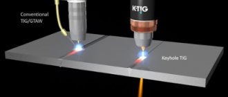
Basics of RDS. Advantages and disadvantages
The creation of one-piece structures using RDS is based on melting the edges of parts while simultaneously filling the weld pool with the liquid metal of the coated electrode. Protection is carried out with the participation of a coating, which, when heated, covers the working area with a film and a mixture of gases, displacing harmful impurities and oxygen.
Thanks to this, work can be carried out both indoors and outdoors. The influence of wind is minimal in contrast to welding in a shielded gas environment. Apart from the welding machine itself and electrodes, nothing is required, so quickly moving equipment around the site does not cause difficulties.
The downside is the difficulty of working with vertical and ceiling seams; in this case, the welder needs to have some experience and appropriate qualifications.
Also recognized as a negative point is low labor productivity compared to the use of semi-automatic equipment.
Three main types of connections
GOST 5264-80 describes all types of standard connections used in production. If joints are used that are not described in the list, then in the accompanying documentation (drawing) the designer makes a footnote indicating the parameters of the seam.
Connection types:
- Butt welding – used for welding sheets and flat parts. There are: with flanged edges, with or without cutting, on a removable or permanent lining.
- Angular - for connecting elements in which the edge of one of them abuts the plane of the second at an angle other than 0 degrees.
- Overlapping - used when installing parts, with the side of one superimposed on the plane of the other.
Types of welded joints
The main purpose of creating a permanent joint is to ensure sufficient strength for the operation of the metal structure.
How to choose the correct electrode diameter
Conventionally, the thicknesses of the welded parts can be divided into three groups:
- thin – up to 2 mm . For work, choose 2-3 mm electrodes;
- average - from 2 to 20 mm . Electrodes from 3 to 4 mm are used;
- thick - over 20 mm . The root of the seam can be welded with 3-4 mm electrodes, and then it is recommended to work with 5 mm electrodes.
Important: at the same current, a thin electrode gives greater penetration of the base metal than a thick one. But work productivity decreases: you have to change them more often.
To facilitate welding in vertical and overhead positions, it is better to use electrodes no thicker than 4 mm.
Approximate cost of electrodes on Yandex.market
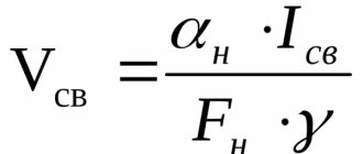
The principle of selecting welding current
When choosing welding parameters, you should be guided by:
- per metal thickness;
- per electrode diameter;
- on the positions of the future seam - horizontal, vertical, ceiling.
Electrode manufacturers place a table with recommended parameters on the packaging, but when welding different alloys, the values may be different. To select the current more accurately, it is better to try different modes on scraps of metal, focusing on those indicated in the table.
When welding in a vertical position, the current is reduced by 10-15%, and for creating ceiling seams - by 20-30%.
Electrode position for manual arc welding
The position of the electrode during the welding process depends on the spatial location of the seam, the thickness and grade of the metal being welded, the diameter of the electrode itself, and the thickness and grade of its coating.
Welding can be done from right to left, left to right, away from you, towards you. In this case, in any direction of welding, the angle of inclination of the electrode should ensure penetration of the metal to a small depth and the correct formation of the weld. The figure on the right shows the recommended position of the electrode when welding in different directions:
Two ways to ignite the welding arc
At the beginning of work, you need to light the arc. There are two ways to do this:
- by tapping the electrode on the base metal - you need to touch the tip to the surface and when an arc column appears, move the rod to a distance at which it will burn steadily;
- by striking - the electrode must be drawn across the metal, like a match along the side of a box until it lights up, and also moved to the required distance.
Important: electrodes whose tips are covered with graphite (in the form of dark gray caps) ignite more easily.
During the welding process, you have to tear off the rod and interrupt the process. In order to easily light the electrode again, you need to break off the protruding coating to expose the metal rod.
Excitation and burning of the arc
The arc is excited in two ways - by touching or striking.
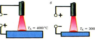
In both cases, the process of exciting the arc begins with a short circuit. At the same time, the current density increases at the contact points, a large amount of heat is released, and the metal melts. Then the electrode is withdrawn, the discharge gap is filled with heated particles of metal vapor, and the arc begins to burn. The welding arc can be excited without the electrode touching the workpiece being welded. To do this, you need to parallelly connect a high voltage and high frequency current source (oscillator) to the welding circuit. In this case, to excite the arc, it is enough to bring the end of the electrode at a distance of 2-3 mm to the surface of the product. The arc gap consists of the most heated areas of the electrode and the base metal (cathode and anode spots) and the arc column. A welding arc, which is characterized by a high concentration of heat and a high temperature reaching 6000-7000 ° C, can melt all metals.
~ 36% of the main amount of arc heat is released in the cathode spot of the welding arc, 21% in the arc column, and 43% of the total arc heat in the anode spot.
The arc length is the distance from the bottom of the crater to the end of the electrode. In manual arc welding, the longer the arc length, the more time the metal drops, passing from the electrode to the crater, will pass through the air, absorbing oxygen from the gas gap. This circumstance causes deterioration in the quality of the weld metal. Arc length is of great importance in welding technology. A long arc burns unsteadily, the area being welded does not warm up well enough, drops of metal falling from the electrode onto a poorly heated area do not completely fuse with the metal being welded. A long arc cannot produce a good quality weld. The arc length should be as short as possible. An arc having a length of 2-4 mm is called short. Welding should be performed with an arc whose length is no more than 4 mm.
A column of burning arc can be considered as a flexible conductor through which electric current passes. Under the influence of the electromagnetic field, which is always present in the product being welded, a deviation of the arc from the direction of the current supply is observed. This phenomenon is called magnetic blast. The deflection of the arc is affected by ferromagnetic masses and the angle of inclination of the electrode during welding. Deviation of the arc from its axis makes welding difficult. To reduce arc deflection, change the location of the current supply, tilt the electrode in the direction of arc deflection, and reduce the arc length.
Welding speed. Arc length
The welding speed depends on the current value and the diameter of the electrode. Thin metals should be cooked quickly to avoid burning. Thick ones, on the contrary, go slowly to ensure good penetration. In each case, the speed of electrode guidance is determined individually.
The tilt of the rod also has an effect - at an angle forward, backward or at 90 degrees:
- angle forward – the tilt is set to 30-50 degrees. Provides reliable protection of the weld pool. If a lot of slag forms in front, then the angle is reduced. The penetration depth with this method is minimal;
- 90 degrees – the degree of penetration of parts is average. Used when it is impossible to guide the electrode in any other way;
- backward angle - maximum penetration of the base metal is ensured. The protective slag follows the electrode without interfering with the work. It is most often used in the lower position, when creating root seams.
The arc length is determined by the distance between the tip of the electrode and the edges of the metal:
- short - on average 3-4 mm. Maximum penetration of the part and stable combustion are ensured. Most commonly used;
- long – over 4 mm. Gives minimal penetration. Since the arc is difficult to hold and there are difficulties in forming a seam, the welder requires experience and high qualifications. Used when welding thin parts to avoid burn-throughs.
To create high-quality seams, you need training. To do this, it is recommended to practice on unnecessary parts before carrying out work, experimenting with the machine settings, the speed of the electrode and its position relative to the direction of welding.
Electrode movement technique for manual arc welding
When welding, the electrode must move in three directions, shown in the figure on the left.
The first movement (direction a) is a translational movement along the axis of the electrode (item 1) into the welding zone. To maintain a stable arc, the speed of this movement is equal to the melting speed of the electrode.
The second movement (direction b) is the forward movement of the electrode along the weld line (item 2). The speed of this movement depends on the strength of the welding current, the diameter of the electrode and other factors.
If the speed is too high, there is a risk of lack of penetration. Such defects in the weld are formed due to the fact that at a high speed of movement of the electrode, the deposited metal does not have time to fuse with the base metal. At a low speed of movement of the electrode, overheating and burning through the metal being welded is possible (especially when welding thin metal) and welding productivity decreases. In the absence of transverse movements of the electrode, the weld is obtained with a width of about 1.5 times the diameter of the electrode. Thin sheet metal is welded using similar seams, and the root of a multilayer weld is also welded.
The third movement of the electrode is the transverse oscillatory movement of the electrode (arrow c). They are used to obtain the required seam width and penetration depth. Transverse movements slow down the cooling process of the resulting weld, promote the removal of gases and slags and ensure good fusion of the base and deposited metal, significantly improving the quality of welding. The crater formed at the end of the bead surfacing is carefully welded.
Technique, basic techniques of manual arc welding
When creating a seam in the lower position, standard techniques are used. The three most commonly used are:
- Guiding the electrode along the edges with minimal vibrations - used when welding corner joints, butt and overlap joints, when installing pipes (forming a fundamental weld). In this case, you need to grab both edges with the tip and not hold the electrode in the middle of the joint.
- Herringbone movement - used when welding subsequent seams (after the root) and facing (external).
- Figure-of-eight method - with this method, maximum penetration of the edges occurs, since the electrode lingers on them. Suitable for welding thick workpieces.
If herringbone welding of vertical seams is used, then 2 options are possible - the semicircles are directed either up or down. In the first case, it is convenient to support the flowing metal, but it is more difficult to hold the arc. The optimal method is selected based on the preferences of the welder.
Arc ignition
Ignition of the arc without the use of a short circuit is especially necessary when welding with a tungsten electrode. This not only simplifies the technique of igniting the arc on the edges being welded, but also significantly reduces the consumption of the tungsten electrode.
Many specialized arc power sources for AC and DC tungsten electrode welding are equipped with devices that facilitate arc ignition . The most widely used are low-power (100-300 W) high-frequency spark generators, called oscillators (Fig. 17.7).
Rice. 17.7. Schematic diagrams of oscillators: a - parallel connection; b - sequential connection
The oscillator consists of a step-up transformer T1 of the oscillatory circuit Kk, a high-frequency transformer T2 of the blocking capacitor Sb, and a noise filter PZF.
The primary winding of the step-up transformer includes elements of a PZF filter designed to reduce radio interference.
The output voltage is usually 3-8 kV. Due to increased magnetic dissipation, the transformer has a falling external characteristic. This eliminates the occurrence of large currents when the secondary winding is shorted to the oscillatory circuit arrester. The primary winding is connected to an alternating current network, usually 220 V.
The main elements of the oscillatory circuit: capacitor Sk, inductive coil Lk and spark gap F. The operating principle of the circuit is the periodic transition of electrical energy stored in the capacitor Sk into the electromagnetic energy of the coil Lk, and vice versa. The oscillation frequency can be determined from the equation
ƒк = (l/2π)√(l/LкСкK)-(R2кK/4L2к) ,
where Rк is the active resistance of the oscillatory circuit.
The presence of active resistance in the circuit causes periodic attenuation of oscillations within each half-full alternating current. The oscillation frequency in modern oscillators is 250-500 kHz.
High-frequency oscillations from the oscillating circuit to the arc gap are transmitted by a high-frequency transformer, the primary winding of which is the inductive coil of the oscillating circuit. The secondary winding Lc is connected in parallel or in series with the arc. In accordance with this, oscillators are distinguished between parallel and serial connection. In series-connected oscillators, the Lc coil may be absent. The coil Lk of the oscillating circuit is connected in series with the arc (Fig. 17.7, b).
The presence of a blocking capacitor eliminates the possibility of injury to workers by high voltage current of industrial frequency. This can happen when the capacitor Ck in the oscillating circuit breaks down.
Parallel-connected oscillators can be used in arc power supplies of any power. They have a number of significant disadvantages, for example, the possibility of high voltage and frequency reaching the arc power source; shunting the arc gap with the Lc oscillator coil; significant radio interference associated with the passage of high frequency current through the windings of the arc power source.
Series oscillators can be used in arc power supplies of a certain power. It is necessary that the rated current of the source be calculated for the coil Lk. Oscillators of this type have the following advantages: sensitivity to radio interference is much less; there is no arc shunting; The Lc coil simultaneously serves as a choke, preventing high voltage and frequency from entering the arc power source.
Along with those considered, oscillators are used with parallel and series connection of the Lc coil of a high-frequency transformer. They are usually called universal.
The power supply circuits provide for automatic switching off of the oscillators after the arc is excited.
Along with oscillators that facilitate arc ignition, other auxiliary devices are also used. Regulators for smooth reduction of welding current at the end of welding (RSCT) are widely used in power supplies. This is necessary to seal the weld crater when it is completed. The most widespread are RSSTs assembled on transistors using a common emitter circuit. The current decay during crater filling occurs exponentially.
What tricks do welders use?
To facilitate welding in different positions, the following methods are used:
- using a lining is convenient for joining thin parts. The lining can be removed after work, then it is better to install copper plates that will not stick to the steel. If you don’t need to remove it, then put in regular leaf trimmings. This way you can melt unnecessary holes and weld thin (0.8-1 mm) parts;
- welding sheets using electric rivets - in cases where tight connections are not needed, you can drill holes with a diameter of 3-4 mm in one of the sheets, place one on top of the other and weld the holes. Warping of parts will be minimal;
- If during installation large gaps have formed between the parts, then you can either place an electrode in the gaps without coating, or disassemble the elements and surfacing the ends . The second method is preferable;
- changing polarity - when welding thin sheets, it is recommended to use reverse polarity (minus on the workpiece) - the risk of burning the part will be less. For deep penetration of the edges, it is better to cook on a straight line - minus on the electrode. It is important to pay attention to the type of electrodes; some brands do not allow polarity changes;
- welding vertical seams from top to bottom - a number of manufacturers produce electrodes that can be used to weld in any direction, including downhill. Example: universal OK 46.00 (for ordinary steels), OK 61.20 (for stainless steel).
To avoid deformation of the parts after welding, you need to assemble them correctly. Once the ends are tacked, the metal structure must be rigid.