Submerged arc welding is one of the first types of welding technologies. The concept of it was introduced by Nikolai Slavyanov in the 19th century. He also introduced the basic terms. The practical implementation of his ideas was carried out by D. Dulchevsky in the 20th century. He used an automated welding complex for flux-cored welding. The method has been constantly improved and has remained popular to this day. The parameters of the connections are regulated by GOST 8713-79 “Submerged arc welding welded joints”. The related document is “Welding at acute and obtuse angles” GOST 23518-79.
Connection type
Automated and mechanized methods are used to weld workpieces.
GOST gives the following definition:
- MF - on weight;
- MFS – cooking;
- MFO – retained backing plate.
GOST describes such types of automatic welding as:
- AFO – backing plate;
- AFF - with flux pad;
- ROS – root area cooking;
- AFP – movable copper substrate;
- AFM – flux-copper substrate.
The document GOST 11534, which regulates flux-cored welding at acute and obtuse angles, further describes the following types:
- P – conventional semi-automatic;
- PS – semi-automatic on a steel backing;
- PPsh – semi-automatic with seam welding;
- Ac – automatic on a steel base;
- Apsh – automatic with welding of the seam.
The work is performed with a non-consumable electrode.
Welding at acute and obtuse angles, according to GOST 11534, requires the use of such types of seams as:
- end-to-end;
- overlap;
- angle;
- T-bar.
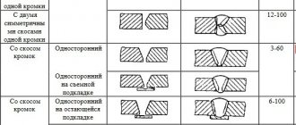
Among butt seams, the following subtypes are distinguished:
- one-sided and two-sided;
- locking with bevel;
- curved bevel;
- beveled symmetrical;
- beveled broken lines;
- planed;
- beveled asymmetrical;
- flanged.
Example of a basic table for a butt weld type C47.
Among the fillet welds there are:
- one-sided;
- double sided;
- bevel;
- flange.
Overlapping and T-joint seams in this classification can be single-sided or double-sided.
Edge preparation form
GOST 8713-79, which describes gas-shielded welding and welded joints, requires high precision when cutting the edges of workpieces . The accuracy requirements for conventional manual MMA or argon arc welding are noticeably lower. An automatic welding machine is adjusted to a specific welding mode, including current strength, distance from the workpiece to the electrode and its trajectory.
During the execution of the programmed program, the automatic device will not be able to take into account inaccuracies in processing or installation of the workpiece, as a qualified and experienced welder could do.
Edge cutting is carried out using gas, plasma or laser cutting machines. Metalworking machines (milling, planing, slotting) are also used. Less commonly used for cutting are water cutting installations.
Before starting work, it is necessary to carry out preparation: clean from mechanical impurities, slag, rust, oil and fat stains . The remaining contaminants, once within the arc's action zone, lead to the formation of such defects as:
- pores and cavities;
- cracks;
- lack of penetration;
- foreign non-metallic inclusions.
Mechanical cleaning is carried out using sandblasting or manual angle grinders. Chemical passivation is also used for better removal of the oxide film. In addition to the edges themselves, the heat-affected area is also cleaned 5-6 mm on each side of the seam. General degreasing with organic solvents or inorganic active substances covers the same area.
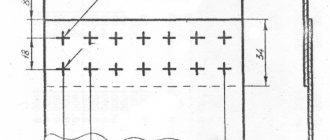
The workpieces must be securely secured to the assembly stand using clamps or special equipment. Tacking in predetermined places by manual electrode welding or in a carbon dioxide environment is also used. Point tacks are made from strips of metal 5-7 cm long. They are installed no further than 40 cm from one another, at the edge they should be no further than 20 cm from the beginning (end) of the seam. They must be cleaned of melt splashes and slags.
To enter and exit the electrode without burning through, inlet and outlet pads are installed at the beginning and end of the seam, cut with the same profile as the main seam.
Operating modes are selected based on the metal of the workpieces, their thickness, and type of cutting. These include:
- operating current and voltage;
- thickness and rate of supply of welding material;
- speed and inclination of electrode movement.
Butt seams are welded with or without groove . The connection can be welded on one or both sides, as well as in several passes.
An example of the main GOST table for connection type C18.
If it is possible to bring the gap between the workpieces to 1 mm, then work in the “boat” position is carried out without a lining. If the gap is larger, a metal or asbestos plate is placed, or a cushion of flux is added. Preliminary welding of the root of the seam from the inside is also used.
Welding in the boat position is recommended for fillet and T welds . It makes it possible to evenly melt the edges and increase the cross-sectional area of the seam. To do this, the workpieces are secured in a special rotary equipment called a tilter. It can rotate together with the workpiece around a longitudinal axis parallel to the seam line. GOST provides for the assembly of a welded I-beam in the same way.
Welding diagrams.
Welding of T-joints and overlap welds is carried out with an angle of inclination of the electrode of 15-30° to the seam line. The disadvantages of this method include the limitation of the maximum leg value of 16 millimeters. To obtain large values, it is necessary to resort to multi-pass boiling.
Submerged arc welding technology
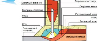
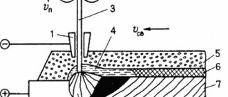
Automatic and mechanized types of welding under a layer of flux differ from traditional technology in that the arc, when performed, does not burn in the open air, but under a layer of bulk substance with a number of special properties, which is called flux. At the moment the welding arc is ignited, the metal of the part and the electrode, as well as the flux used, begin to melt simultaneously. As a result of metal and flux vapors formed in the welding zone, a gas cavity is formed, which is filled with the resulting vapors mixed with welding gases.
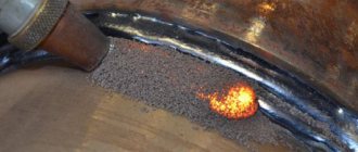
An example of the appearance of a seam after submerged arc welding
The cavity formed during such welding is limited in its upper part by a layer of molten flux, which performs not only a protective function. The molten metal of the electrode and the part being welded, interacting with the flux, undergoes metallurgical processing, which helps to obtain a high-quality weld.
When the arc is removed from a certain welding zone, the molten flux solidifies, forming a hard crust on the finished seam, which is easily removed after the product has cooled. If automatic submerged arc welding is performed, then unused flux is collected from the surface of the part using a special suction device equipped with automated equipment.
In the video, the master explains some of the nuances of welding using flux:
Submerged arc welding, performed both mechanized and automated, has a number of significant advantages.
- The process can be carried out using currents of significant magnitude. As a rule, the current strength when performing such welding is approximately in the range of 1000–2000 Amperes, although it is quite possible to increase this value to 4000 A. For comparison: conventional arc welding is performed with a current strength of no more than 600 A, a further increase in the current strength leads to severe spattering of metal and the inability to form a weld. Meanwhile, increasing the current allows not only to significantly speed up the welding process, but also to obtain a welded joint of high quality and reliability.
- When welding is performed under a layer of flux, a closed arc is formed, which melts the metal of the part to a great depth. Thanks to this, the edges of the part to be welded do not even need to be prepared for their better weldability.
- Since submerged arc welding modes involve the use of high current, the speed of the process increases significantly. If we compare the speed of welding performed under a submerged arc layer, which is measured in the length of the seam obtained over a certain period of time, then it can be 10 times higher than that of conventional arc welding.
- The so-called gas bubble, formed when welding under a protective layer of flux, prevents metal spattering, which makes it possible to obtain high-quality welds. In addition, this significantly reduces the loss of electrode metal, which amounts to a maximum of 2% of the mass of the molten material. In this case, not only electrode material is saved, but also electrical energy.
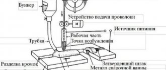
General diagram of submerged arc welding
The choice of welding mode performed under a submerged arc layer is carried out according to the following main parameters:
- diameter of the electrode wire used;
- type of current and its polarity;
- the speed at which welding is performed;
- voltage to form a welding arc.
Additional parameters that influence the determination of the submerged arc welding mode are:
- particle size, composition and density of the flux used;
- value of electrode wire extension;
- a parameter that determines how the electrode and the part being welded are positioned relative to each other.
Character of the weld
Single-sided welding of joints is used for less critical connections . It is also used in cases where it is not possible to gain access to the reverse side. The large size of the weld pool, its relative overheating, and a large volume of melt often lead to splashing of the melt and its leakage through the gap. To prevent an undesirable effect, use backing plates made of steel or copper, as well as flux. The most common methods for making one-sided seams are:
- Flux pad . Flux powder is poured under the edges to be joined in a layer of 3-7 cm. Pressing is carried out using its own weight or using a rubber cylinder filled with compressed air. For small connection sizes, a rubber hose is used. A layer of flux powder prevents the molten medium from flowing out and prevents air from entering the weld pool.
- Copper backing plate . Copper has a high thermal conductivity coefficient. This property is used to remove excess heat from the work area. This prevents burnout of the workpiece material. In addition, the plate prevents the melt from flowing out through the gap. A longitudinal recess is made in the plate opposite the seam, and it is filled with flux powder. Thanks to this notch, a welding bead is formed on the underside of the joint. The copper plate has a width of 4 to 6 cm and a thickness of 0.5 to 3 cm.
- Copper slider . A massive water-cooled shoe moves parallel to the electrode on the reverse side on studs. Rollers can be used to reduce friction.
- Steel backing plate . If the design allows, a contact strip 2-5 cm wide and half a centimeter thick made of the same alloy as the workpiece is placed on the back side. It is installed with a minimum gap and tacked every 40 cm by capacitor welding. The plate is boiled together with the workpieces, becoming part of the suture material. This not only prevents melt leakage, but also increases the strength of the seam.
- Underwelding seam . Manual welding forms the root of the seam, securely fixes the workpieces and prevents melt leakage.
Methods of protection against leakage, types of linings.
Double-sided welding of joints forms a stronger and more durable seam . This method is used during the assembly of industrial installations, machine tools, vehicles, building structures, critical and loaded products with high specific strength. Welding on both sides allows the seam to withstand both static and dynamic loads on an equal basis with the main material of the product.
When making a joint in two passes, first weld the seam from the front side, reaching a penetration depth of 60-70% of the height. Before this, the workpieces are carefully adjusted to each other, the gap should not exceed 1 mm. Various lining agents are not used; the surface tension forces of the melt are sufficient to avoid leakage. At the next stage, the seam is passed from the wrong side, forming its full profile.
If, for structural or technological reasons, it is not possible to ensure a small gap, use the same methods to prevent leakage as with the one-sided method:
- copper backing plate;
- steel plate;
- a layer of flux powder;
- manual cooking.
Corner, T- and lap seams are welded, placing the workpieces in a boat. When welding from the reverse side, the tilter with the workpieces fixed in it is turned to the required angle.
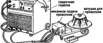
Equipment used for submerged arc welding
Let's take a look at existing submerged arc welding equipment. When it comes to carrying out welding work in a production workshop, before starting the welding process, the parts to be welded are securely fixed on a special assembly stand or using other devices in order to completely eliminate possible unplanned movements of the elements being welded during work.
Welding tractor (manufacturer: Multitrac)
When laying pipelines, special mobile welding heads are mainly used for welding joints, and in the production of sheet structures, either stationary installations or universal mobile ones (for example, a welding tractor) are used. The submerged arc welding tractor is a self-propelled trolley with an electric motor on which an automatic welding head is installed. Such a device can move along the parts being welded along a rail track or directly along the parts themselves.
Welding column and welded part on roller supports
In workshop conditions, mobile or stationary welding columns are also actively used, which, in combination with roller bearings or rotators, are used for welding longitudinal and circumferential seams.
Thickness of welded parts
This is an important parameter that determines the choice of one technology or another, the method and specific shape of edge cutting, the number of sides of the seam and the number of passes. Thin workpieces (up to 1 mm) are welded using the “flanging” cutting technique . It allows you to avoid burn-through, increase the contact area of the workpieces and increase the strength, durability and tightness (if necessary) of the connection. Workpieces from 1 to 4 mm are welded without cutting edges.
The small thickness allows for complete penetration and high quality seams. Workpieces thicker than 4 mm are edge-cut. This is necessary to ensure access of the electrode to the root of the seam to achieve complete and high-quality penetration.
For parts thicker than 60 mm, special cutting profiles are used, various curved or stepped, and the seam is welded in several passes . GOST also regulates welding mixtures depending on thickness.
Welding process
When parts are welded using flux, the arc burns using the original granular powder. The high temperature causes the electrode and surrounding granules to melt. As a result, an elastic film appears that surrounds the welding area .
The film blocks the access of oxygen to the welding arc. The seam is obtained without cracks or cavities. After cooling, the flux turns into slag, uniformly covering the seam. When the operation is completed, the hard crust is removed mechanically. The remaining flux is used for further operations. This “loose blanket” is suitable for work on various equipment.
The smallest value of legs for different thicknesses of workpieces
The standard sets the lowest values when the workpieces have different thicknesses. If the difference is smaller, then welding is carried out as for parts of equal thickness.
Limit difference in thickness.
If the difference is greater, then the thick part is chamfered to the thickness of the thin part. It is also possible to make a seam with an inclined surface, which transitions from workpiece to workpiece.
Positive characteristics
To implement this technology, welding current is supplied to the wire through a special mouthpiece. It is located approximately 70 mm from the edge. In this case, the electrode cannot overheat. High current can be used for operation. The result is fast surfacing and good deep penetration. Very thick metal can be welded without first cutting the edges.
When automatic arc welding is performed, a constant seam size is maintained. It turns out to be the same shape and has a homogeneous chemical composition. The result is a high-quality connection that is highly stable. This technology prevents the appearance of defects associated with the appearance of undercuts and metal fusion.
Flux protects against splashing. The surrounding surface will not need to be cleaned of welding spatter.
Flux welding is considered a high-performance process, which significantly saves energy, together with welding materials. Savings reach 30-40%.