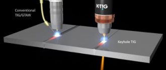
How to calculate welding speed
Welding speed is directly dependent on the size of the current, so you should first understand it. Welding current is calculated using formulas.
There are formulas by which the welding speed is calculated depending on the current value. This, in turn, can be calculated using the welding current formula. By correctly applying the formula for calculating the welding current, you can find its value and select the optimal welding speed, which depends on various characteristics.
So, for example, knowing the parameters of the deposited metal and the current value, you can apply the following formula:
αн is the deposition coefficient; γ —density of the electrode metal in g/cm3; Fн - metal area in cm2.
The deposition coefficient αн depends on the characteristics of the electrode. The metal area refers to the cross-sectional area of the welded seam under the condition of a single-pass option or one layer if a multi-layer coating is carried out.
To calculate this characteristic it is not necessary to use the welding speed formula. Regulatory documents can help, which contain recommendations on the choice for each type of metal. When asking how to calculate the welding speed, you can focus not only on the formulas, but also on the values indicated in them.
Electrode diameter and metal thickness
The magnitude of the welding current and the diameter of the electrode are the main parameters that determine the stability of the welding process and the quality of the resulting joint. The optimal value depends on the type of metal, joining technology, and surface preparation. For example, when welding parts with preliminary cutting of edges, it is recommended to use an electrode with a diameter of 2 or 3 mm to perform the root weld. Subsequent layers are applied using rods whose diameter depends on the conditions of the work.
If there are no edges, you can use a simple table:
| Edge thickness, mm | Electrode diameter, mm |
| Less than 2 | Less than 2 |
| 3-5 | 3-4 |
| 6-8 | 4-5 |
| 9-12 | 5-6 |
| 13-15 | 6-7 |
| 16-20 | 7-8 |
| More than 20 | 8-10 |
Influence of speed on weld configuration
As the welding speed increases, the weld width decreases. The depth of penetration first tends to increase, and then it begins to decrease.
Compensation is carried out by increasing the current value. At a high welding speed, undercutting of the welded seam may occur, on both sides. This is due to heating that is insufficient to obtain a high-quality seam.
If the metal is thick, it makes sense to weld it with narrow seams, while ensuring high speed. Slow welding can lead to the appearance of defects in the metal in the form of pores.
Type and polarity of current
AC welding is used to join low-carbon and low-alloy steels (type 09GS) in construction and installation conditions with rutile-coated electrodes. For welding thick structures made of low-carbon steels. If magnetic blast occurs during welding with direct current sources.
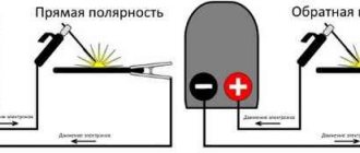
DC welding can be divided into two processes - manual arc welding with direct and reverse polarity.
On straight polarity
Direct polarity is used for welding cast iron and deep penetration of the base metal. For welding low-, medium-carbon and low-alloy steels with a thickness of 5 mm or more using electrodes with calcium fluoride coating: UONI-13/45, UONI-13/55, etc.
On reverse polarity
Reverse polarity is used for welding sheet metal of low thickness and welding with an increased melting rate of the electrode. For welding low-carbon steels (type 16G2AF), low-, medium- and high-alloy steels and alloys.
To indicate a certain type of current, the designations AC and DC are often used today. The abbreviations AC and DC (short for alternative current and direct current) mean alternating and direct current, respectively.
Manual welding
The speed of manual arc welding is chosen by the welder himself, so a lot depends on his qualifications. His choice is influenced by:
- properties of the base metal;
- characteristics of the electrode used;
- position of the seam in space.
The requirement that is imposed on the result of the choice is that it must guarantee a slight elevation of the molten metal located in the weld pool above the edges of the main one. A smooth transition of the liquid metal to the base metal without the occurrence of defects in the form of sagging and undercuts must also be ensured. When high-alloy steels are welded, welding is carried out at high speed in order to prevent overheating.
This parameter depends on the coating of the electrodes used. When using electrodes with a rutile coating, the welding speed is selected in the range of 6-12 m/h, with cellulose-coated electrodes - 14-22 m/h.
From the welding speed table for manual arc welding, you can find the value of this parameter depending on the thickness of the metal material.
Speed of work in manual arc welding
The speed at which the electrode moves along the welding joint affects the width of the seam. The faster the welder moves the electrode, the thinner the seam will be, and, conversely, the slower the consumable moves, the more weld deposit remains at the joint. In addition to longitudinal movements, the welder also makes transverse movements. They determine the width and depth of the seam.
You should not cook too quickly or too slowly. In the first case, hollow inclusions will form. The space not filled with melt is a potential weak point that could cause a crack. Slow movement of the electrode causes the melt to spread, which reduces the quality of the welded joint. In addition to the translational movement of the electrode, there are also transverse movements of the end: herringbone, zigzag, ladder and others.
We can summarize briefly: the choice of manual arc welding mode is a set of actions by the welder designed to resolve the issues of finding optimal welding parameters for specific workpieces under certain conditions. At first, it will be difficult for beginners to choose the most suitable welding mode for specific conditions. To help them, manufacturers of equipment and consumables provide reference books, instruction manuals and other informational materials. Over time, experience comes and the need to look into various kinds of instructions gradually disappears.
Semi-automatic welding
A semi-automatic welding machine is a device in which the role of an electrode is played by a wire fed to the welding site automatically. When welding with a semi-automatic machine, it is necessary to set two speeds. Both are installed by a welder. The first of these is the speed at which the wire is fed. The right choice will ensure a stable burning of the welding arc.
Second, the welding speed depends on the speed at which the torch moves. Thick-walled joints are welded at high speed to form narrow seams. At high speeds, it is necessary to ensure that when the gas leaves the protection zone, there is no oxidation of the end of the wire and the metal surface. Just as with manual arc welding, the current strength and feed speed of the electrode, in this case the wire, must be set by the welder himself, guided by his experience and qualifications. You have to start, in particular, from the type of metals being fused.
Using a semi-automatic welding machine, you can join two metal parts quickly and efficiently. This machine can weld metals of various widths. Compared to manual welding, semi-automatic welding has significant advantages.
Before starting the process, it is necessary to calculate the main characteristics - current, arc voltage and welding speed. The last parameter can be calculated knowing the selected current and voltage, since the semi-automatic welding speed depends on them.
Current and voltage, in turn, are selected in accordance with the thickness of the metal. It turns out that the speed of semi-automatic welding depends on the thickness of the metal.
First, the current strength is calculated using the formula. It is calculated depending on the diameter of the electrode and the current density. Knowing the calculated current strength and the diameter of the electrode, using the formula, you can determine the value of the welding arc voltage. After this, you can select the optimal welding speed.
Welding current
Current has defining properties: type, polarity and strength. By type, current is divided into direct and alternating. Polarity can be direct or reverse.
Most welding machines operate on direct current. The difference between direct current and alternating current is that direct current does not change in direction or magnitude. Thus, it ensures the stability of the arc. The only disadvantage of direct current in the process of joining metals is the possibility of a magnetic blowing effect. It occurs when connecting large structures, when an extraneous magnetic field (from magnetized products) affects the magnetic field of the arc. In this case, the arc begins to “run out” beyond the area where the seam is located and combustion stability decreases sharply. This disadvantage can be combated by
- fencing the work area with special screens that protect from “extra” magnetic fields
- grounding of welded surfaces
- identify possible options for using alternating current
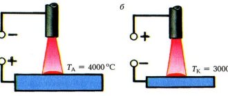
The advantage of working on direct current is a stable arc and the ability to select polarity. Direct polarity is also called electrode-negative, reverse polarity is also called electrode-positive. Reverse polarity occurs when the electrode is connected to the positive and the metal to the negative. With direct polarity, the opposite is true. The difference between the polarities is as follows. The laws of physics say that where the plus is connected, that element heats up more. Thus, with straight polarity, the metal product heats up more. This polarity should be used to join thick parts, since this process requires more melting of the metal to obtain a good weld. If direct polarity is used on a thin product, it will “burn” and the seam will turn out to be of poor quality. For thin metals, reverse polarity is carried out.
The amount of current is determined by the characteristics of a particular welding machine. In modern models, these indicators are indicated in the instructions. If for some reason you do not have instructions, then the current strength can be selected depending on the diameter of the electrode used. It is not allowed to use a current strength that is more suitable for a particular electrode. In this case, the electrode coating used to make the connection will be damaged and the arc will operate unstably. Using an electrode that is too large also has a bad effect on the process of joining metals: the current density decreases, the arc “runs away,” its length changes, and the weld does not turn out smooth and of high quality.
The benefits of making the right choice
Correctly selected parameters will ensure a high-quality metal connection that can last for many years. The use of ready-made formulas makes it easier to select parameters. But this does not exempt you from studying GOSTs and other regulatory materials.
An experienced welder must cope with a non-standard situation and make adjustments. The correct choice of welding characteristics, in particular, the speed at which it will be carried out, will allow you to obtain high-quality and durable seams.
Electrode type and brand
First of all, it is necessary to select electrodes that ensure uniformity of the chemical composition of the base metal and the metal rod of the electrode. Also, the type and brand are selected depending on the spatial position of the seam, the required density of the seam, ambient temperature, strength of the product and operating conditions of the structure. Using an electrode, you can give the seam the necessary properties.
You can select the type and brand of electrode using the electrode catalog on our website, which already contains more than 200 brands of electrodes. All brands are divided into categories according to the type of metal for which they are intended and are further divided into types. If electrodes are designated according to foreign standards, you can find their domestic analogues in our catalogue.
Selecting current depending on the diameter of the electrodes
Thin metal, no more than 1 mm thick, is welded with 1 mm electrodes, and the current strength is set to the minimum possible values, in the range of 10-30 A. When welding thicker metal, up to 2 mm, electrodes of a slightly larger diameter are used, 1. 5 or 2 mm. The current strength for welding with these electrodes is set in the range of 30-50 A.
A 3 mm electrode is used to weld metal up to 4 mm, and the current on the inverter is set to 60-120 A. For welding metals over 10 mm thick, much thicker electrodes are already used - 4 and 5 mm. For their normal use, the welding machine must be set to a current of more than 120 A.
Extra options
Electric arc welding modes include not only basic, but also parameters that complement them. Such arc welding modes also influence the final weld.
Electrode stick out
Electrode extension is the distance from the end of the electrode to the surface of the metal part. It influences the welding process and the size of the resulting seam.
Increasing this parameter reduces the stability of the arc. The metal begins to spatter more strongly. The small overhang makes it difficult to observe the welding process. Spraying occurs on the nozzle.
Electrode coating thickness
Manual arc welding modes include the characteristics of the electrodes, in particular, its coating, namely its thickness. This parameter is regulated by GOST 9466. Optimal coating requires its end size to be in the range of 0.5-2.5 mm. The use of current conductors with such a coating thickness ensures a durable seam that can withstand heavy loads.
Number of passes
The single-pass welding method involves welding in one layer. No oscillatory movements are made. It is used when welding parts of small thickness, when the seam width does not exceed 14-15 mm. At the same time, the magnitude of residual deformations decreases. For butt joints, especially when welding thick elements, several layers are used, and this method is called multi-pass.
A seam made in one pass has a larger pool. The advantages are the high productivity of the process and the cost-effectiveness of the method. Disadvantages include reduced weld ductility and too large heating zone. All seams in multi-pass welding are made with electrodes of the same size.
Manual arc welding modes
Proper arc maintenance and movement is the key to quality welding. An arc that is too long promotes oxidation and nitriding of the molten metal, spatters its droplets and creates a porous weld structure. A beautiful, even and high-quality seam is obtained with the correct choice of arc and its uniform movement, which can occur in three main directions.
The forward movement of the welding arc occurs along the axis of the electrode. With this movement, the required arc length is maintained, which depends on the melting rate of the electrode.
As the electrode melts, its length decreases, and the distance between the electrode and the weld pool increases. To prevent this from happening, the electrode should be moved along the axis, maintaining a constant arc. It is very important to maintain synchronicity.
That is, the electrode moves towards the weld pool synchronously with its shortening.
The longitudinal movement of the electrode along the axis of the welded seam forms a so-called thread welding bead, the thickness of which depends on the thickness of the electrode and the speed of its movement.
Typically, the width of the thread welding bead is 2 - 3 mm larger than the diameter of the electrode. Strictly speaking, this is already a welding seam, only a narrow one. For a strong welding connection, this seam is not enough.
And therefore, as the electrode moves along the axis of the weld, a third movement is performed, directed across the weld.
The transverse movement of the electrode allows you to obtain the required seam width. It is performed by oscillatory movements of a reciprocating nature.
The width of the transverse vibrations of the electrode is determined in each case individually and largely depends on the properties of the materials being welded, the size and position of the seam, the shape of the groove and the requirements for the welded joint. Typically, the width of the seam lies in the range of 1.5 - 5.0 electrode diameters.
Thus, all three movements overlap each other, creating a complex trajectory of the electrode. Almost every experienced craftsman has his own skills in choosing the trajectory of the electrode, drawing intricate shapes with its end.
Classic trajectories of electrode movement during manual arc welding are shown in Fig. 1.
But in any case, the arc movement trajectory should be chosen in such a way that the edges of the parts being welded are fused to form the required amount of deposited metal and the specified weld shape.
If the weld is not completed before the length of the electrode decreases so much that it requires replacement, then welding is stopped for a while. After replacing the electrode, remove the slag and resume welding.
To complete a broken seam, strike an arc at a distance of 12 mm from the depression formed at the end of the seam, called a crater.
The electrode is returned to the crater to form a fusion of the old and new electrodes, and then the electrode begins to move again along the originally chosen path.
Arc welding diagram
The order of filling the seam along the cross-section and length determines the ability of the welded joint to absorb given loads and affects the magnitude of internal stresses and deformations in the seam mass.
Seams are distinguished: short - the length of which does not exceed 300 mm, medium - 300 - 100 mm long and long - over 1000 mm. Depending on the length of the seam, its filling can be carried out according to various welding filling schemes, which are presented in Fig. 2.
In this case, short seams are filled in one pass - from the beginning of the seam to its end. Medium-length seams can be filled using the reverse-step method or from the middle to the ends. To perform the reverse-step filling method, the seam is divided into sections whose length is 100-300 mm. In each of these sections, the seam is filled in the direction opposite to the general welding direction.
If one pass of the welding arc is not enough to fill the seam normally, multilayer seams are applied. Moreover, if the number of applied layers is equal to the number of passes, the seam is called multilayer. If some layers are performed in several passes, such seams are called multi-layer-pass. Such seams are shown schematically in Fig. 3.
| Rice. 2. Arc welding schemes: 1 - pass welding; 2 - welding from the middle to the edges; 3 - reverse-step welding; 4 - block welding; 5 - cascade welding; 6 - welding with a slide | Rice. 3. Types of seams: 1 - single-layer; 2 - multi-pass; 3 - multi-layer, multi-pass |
From the point of view of labor productivity, the most appropriate are single-pass welds, which are preferred when welding metals of small (up to 8-10 mm) thicknesses with preliminary cutting of the edges.
But for critical structures (pressure vessels, load-bearing structures, etc.) this is not enough.
Internal stresses arising during the welding process can cause cracks to appear in the weld or in the heat-affected zone due to insufficient ductility of the weld and high rigidity of the base metal.
When welding products with relatively low rigidity, internal stresses cause local or general warping (deformation) of the structure being welded. In addition, when welding metals with a thickness of more than 10 mm. volumetric stresses appear and the risk of cracks increases.
In such cases, a number of measures are taken to reduce stress and deformation: welds of a minimum cross-section, welding with multilayer seams, seams using “cascade methods” or “slide”, forced cooling or heating are used.
When welding “slide”, first a first layer is laid at the base of the cut edges, the length of which should be no more than 200 - 300 mm. After this, the first layer is covered with a second one, the length of which is 200 - 300 mm longer than the first. The third layer is applied in the same way, overlapping the second by 200 - 300 mm.
In this way, filling is continued until the number of layers in the area of the first seam is sufficient for filling. The next layer is applied at the end of the first layer, overlapping the last one (if the length of the seam allows) by the same 200 - 300 mm.
If the first seam was laid not at the beginning of the seam, but in its middle part, then the slide is formed sequentially in both directions (Fig. 2, f). So, forming a slide, the entire seam is sequentially filled.
The advantage of this method is that the welding zone is in a heated state all the time, which helps to improve the physical and mechanical properties of the seam, since internal stresses are minimal and the appearance of cracks is prevented.
The “cascade method” of filling a seam is essentially the same “slide”, but it is performed in a slightly different sequence.
To do this, the parts are connected to each other “on tacks” or in special devices.
Lay the first layer, and then, stepping back from the first layer at a distance of 200 - 300 mm, lay the second layer, covering the area of the first (Fig. 2, e). Continuing in the same sequence, fill the entire seam.
Fillet welds (Fig. 4) can be performed using two methods, each of which has its own advantages and disadvantages. When welding “in the corner,” a larger gap between parts is allowed (up to 3 mm), assembly is easier, but the welding technique is more complicated.
In addition, undercuts and sagging are possible, and productivity is reduced due to the need to weld small-section seams with a leg less than 8 mm in one pass. Boat welding allows for larger seam legs in one pass and is therefore more productive.
However, such welding requires careful assembly.
The indicated arc welding techniques were considered at the lower positions of the seam, the implementation of which is the least labor-intensive.
In practice, it is often necessary to perform horizontal seams on a vertical plane, vertical and ceiling welding.
To perform these works, the same techniques are used as for seams with a lower position, but the labor intensity of the work and some technological features require a more detailed approach and changes in some methods.
When welding such seams, there is a possibility of molten metal leaking out, which leads to drops falling to areas unfilled by welding, molten metal flowing along horizontal planes, etc.
| Rice. 4. Position of the electrode and the product when making fillet welds: A - symmetrical boat welding; B - in an asymmetrical “boat”; B - “in the corner” with an inclined electrode; G - with melted edges | Rice. 5. The influence of welding speed on the shape of the weld: With increasing speed, a noticeable decrease in the width of the weld is observed, while the depth of penetration remains almost unchanged. |
Considering the essence of the processes occurring in such seams, we said that surface tension forces can hold the metal in a molten bath. In order for these forces to be sufficient, the welder must be masterful in welding techniques. Here it is necessary to reduce the welding current and use electrodes of reduced cross-section.
This ultimately affects productivity as the number of welding passes has to be increased. Therefore, in practice, they try to add a “surface tension film” in addition to surface tension forces.
The essence of this method is that the arc is not held constantly, but at certain intervals, that is, pulses.
To do this, the arc is constantly interrupted, igniting it at certain intervals, allowing the molten metal to partially crystallize. It is here that the welder’s ability to choose such intervals is manifested when the welding leg does not have time to form and at the same time the metal would lose part of its fluidity.
The ceiling seam is the most difficult. Therefore, carrying out it with continuous arc burning is a futile task. Welding is performed by short-circuiting the arc to the weld pool so that it does not have time to cool, replenishing it with new portions of molten metal.
When welding with this method, you should monitor the size of the arc, since its lengthening can cause unwanted undercuts. In addition, when welding such seams, unfavorable conditions are created for the release of slag from the molten metal, which can lead to porosity of the weld.
Vertical seams can be welded in two directions - from bottom to top and from top to bottom. Both methods have a right to exist, but uphill welding is always preferable. In this case, the metal located below holds the weld pool, preventing it from spreading.
When welding downhill, it is more difficult to hold the weld pool, and therefore it is much more difficult to achieve a high-quality seam. The essence of this method is practically no different from ceiling welding, and it is used when upward welding is technologically impossible.
Horizontal seams on a vertical plane also have their own characteristics. In these welds, it is particularly difficult to retain the weld pool at both edges of the parts being welded.
To facilitate this process, the bottom edge is not beveled. In this case, a shelf is obtained that helps hold the molten weld pool in place.
Pulse welding with short-term ignition of the arc is also appropriate here, as for ceiling seams.
Welding slag is removed with a chipping hammer. To do this, wait until the workpiece has cooled down enough that it can be picked up by hand, press it firmly to the table and, with hammer blows directed along the seam, remove the slag covering the weld seam.
After this, the seam is forged to relieve internal stress. To do this, the hammer head is turned along the seam and forged along its entire length.
Finish cleaning with a stiff wire brush, moving it with sharp movements, first along the seam and then across it, to remove the last remnants of slag.
| Rice. 6. The influence of the angle of inclination of the product on the shape of the weld: When welding uphill, a large depth of penetration is observed, as well as a large height of the bead. When welding downhill, on the contrary, the depth of penetration decreases and the height of the weld decreases. In this case, the width of the seam practically does not change. | Rice. 7. Influence of the position of the electrode on the shape of the weld: The figure shows that when welding with a backward angle, the penetration is deeper, and when welding with a forward angle, the width of the seam increases and the height of the bead decreases. |
| Rice. 8. The influence of welding speed on the shape of the weld: The position of the weld pool when the product, arc or electrode is tilted. Downhill welding, uphill welding, forward angle welding. | Rice. 9. The influence of preparing edges for welding in butt joints. |
| Rice. 10. Elements of a butt weld, fillet weld and bead on a plate: B - width of the weld; K - seam leg | Rice. 11. Influence of the welding current during welding: If the welding current is changed during welding, the parameters of the weld cross-section will change. At a lower current, the penetration depth increases and the weld bead increases. |
Reproductions used https://welding.su/gallery/
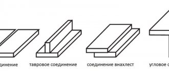
Types of welds
- By position in space
- lower - located in a horizontal plane or in a plane located at an angle of 60-120 degrees to the horizontal plane;
- vertical – located in a vertical plane at an angle of 60-120 degrees to the horizontal;
- ceiling - located in a plane at an angle of 120-180 degrees to the horizontal;
- horizontal - located in a vertical plane horizontally.
- with reinforcement (convex);
- without enhancement (normal);
- weakened (concave).
By number of layers:
- single-layer;
- multilayer.
- continuous (solid) - without gaps along the length of the seam;
- intermittent - with intervals along the length of the seam.
The types of welded joints and the shape of the edges are shown in Fig. 1.
Welding technology
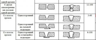
To obtain penetration over the entire section, depending on the type of welded joint and the thickness of the elements being connected, the edges are separated. Edge cutting for welding is carried out by mechanical processing and gas cutting. The type of connection, the shape of the edges, the welding method and the dimensions of the seam are provided for by the relevant GOSTs and are indicated in the drawing of this design. To reduce deformation in the structure, tack joints are performed before welding. The recommended number of passes when welding structures, depending on the thickness of the metal, is indicated in Table 1.
Fig.1. Types of welded joints: a – stacked, b – corner; c – tee; g – overlap; 1 – with flanged edges; 2 – without cutting edges; 3 – B-shaped cutting; 4 – x-shaped cutting; 5 – U-shaped cutting; 6 – K-shaped edge preparation
Table 1
| Arc welding mode is a combination of factors that ensure the production of a weld of good quality and specified dimensions. Such factors include the type and polarity of the welding current, its magnitude, type and brand of electrode, its diameter, arc voltage, position of the seam in space, and welding speed. The type of welding current - direct or alternating - and its polarity depends on the brand and thickness of the metal being welded; these data are given in tables with the characteristics of various brands of electrodes. The type and brand of electrode can also be selected using these tables. The diameter of the electrode, depending on the thickness of the parts being welded, can be selected according to the table. 2. Table 2. Electrode diameter depending on the thickness of the metal being welded | 3…5 | 4…10 | 12…24 | 30…60 | |
| Electrode diameter, mm | 2…3 | 3…4 | 4…5 | 5…6 | 6…8 |
When welding multilayer seams, the first seam is welded with an electrode with a diameter of no more than 4 mm, and with an electrode diameter larger than this, there may be a lack of penetration of the root of the seam.
The diameter of the electrode when welding vertical seams is no more than 5 mm, ceiling seams - no more than 4 mm, regardless of the thickness of the metal being welded. When choosing the diameter of the electrode for welding corner and T-joints, the leg of the weld is taken into account. The diameter of the electrode at the weld leg is 3...5-3...4 mm, at the weld leg 6...8-4...5 mm.
The amount of welding current depending on the diameter of the electrode is printed on the packaging of the electrodes.
For welding in the lower position, the value of the welding current can be determined by the formula:
Ist = (40…60)d,
where Iw is the welding current value, A; 40...60 - coefficient depending on the type and diameter of the electrode; d—electrode diameter, mm.
When welding structural steels:
- for electrodes with a diameter of 3...6 mm, the value of the welding current: Iw = (20 + 6d)d;
- for electrodes with a diameter of less than 3 mm: Isv = 30d,
where Iw is the welding current value, A; d—electrode diameter, mm.
The magnitude of the welding current depends both on the diameter of the electrode and on the length of its working part, the composition of the coating, and its position in the welding space.
The amount of metal deposited during welding depends on the value of the welding current:
Q = αнIсвt,
where Q is the amount of deposited metal, g; αн — deposition coefficient, g/(A•h); Iw - welding current, A; g - welding time, hours.
But with a welding current that is unacceptable for a given diameter of the electrode, the electrode quickly overheats, which leads to a decrease in the quality of the weld and spattering of the metal.
If the welding current is insufficient, the arc is unstable and there may be lack of penetration in the weld.
The arc voltage varies in the range of 16…30 V.
Butt welds Metal thickness, mm 2 3 4 5 6 8 10 12 14 16 18 Number of passes (at the rear of the weld) 1 1 1 1 2 2-3 3-4 4 4-5 5-6 5-6 Fillet welds Metal thickness, mm 2 4 6 8 10 12 14 16 18 20 22 Number of passes (at the rear of the weld) 1 1 1 1 2 2-3 3-4 5 5-6 5-6 6-7Selecting the manual arc welding mode
The welding mode is selected depending on:
- grade and thickness of steel being welded;
- diameter and grade of the welded rod;
- composition of the coating and spatial composition of the seam being performed.
The type and brand of electrode is selected depending on:
- base metal grades;
- required properties of the deposited metal;
- position of the seam in space;
- edge cutting forms;
- kind of current;
- power supply, etc.
The diameter of the electrode is taken depending on the thickness of the metal being welded and the nature of the welded joint (Table 2).
table 2
| Metal thickness, mm | Electrode diameter, mm |
| 1-2 | 1-2 |
| 3 or more | 3 |
| 4 or more | 4 |
| 4-8 | 4 |
| 9-12 | 4-5 |
| 13-15 | 5 |
| 16-20 | 5-6 |
| 28 or more | 6 |
Welding can be performed with a direct current or alternating current arc. DC arc welding can be done with direct (minus on the electrode, plus on the product) or reverse (plus on the electrode, minus on the product) polarity. Reverse polarity is recommended when welding most alloy steels, cast iron, copper, aluminum, and thin carbon steel sheets. The AC arc is less stable. To increase its stability, the open circuit voltage of the current source is required to be at least 55-70V. In addition, electrodes with a special coating are used for welding with alternating current. The amount of molten metal under the influence of the heat of the arc per unit time is the melting productivity and it is directly proportional to the strength of the welding current. The strength of the welding current is selected depending on the diameter of the electrode (Table 3).
Table 3
| No./item | Welding conditions | Current strength, A |
| 1 | Welding in the lower position with electrodes with a diameter of 4-5 mm with a metal thickness of (1.5-3) dе | (40-50)de |
| 2 | The same when welding with electrodes with a diameter of up to 4 and more than 5 mm | (20-68)de |
| 3 | Welding in the lower position, welding cast iron and steels | (25-35)de |
| 4 | Welding metal with a thickness of less than 1.5 dE | Reduce by 10-15% compared to point 1 |
| 5 | Welding metal with a thickness of more than 3 dE | Reduce by 10-15% compared to point 1 |
| 6 | Welding in a vertical plane | Increase by 10-15% compared to the current strength when welding in the lower position |
| 7 | Welding in ceiling position | Reduce by 15-20% compared to the current when welding in the lower position |
The lower current limit for given diameters and brand of electrode is determined by the stability of the arc, and the upper limit is determined by overheating of the electrode during welding.
Also, the welding current can be set depending on the required penetration depth on the basis that on average every 80-100A gives a penetration depth of 1 mm, i.e.
(1)
where n is the thickness of the material (n=3).
The voltage is measured within a narrow range (20-50V), its value is recommended in the electrode data sheets.
When manual arc welding, it is important to maintain a certain arc length (the distance between the end of the electrode and the bottom of the weld pool), which must be
(2)
The multiplier of 0.5-1.1 depends on the welding conditions and the brand of electrode. On reverse polarity, the arc length should not exceed 2.5 mm, and on alternating current - 4 mm. Its increase leads to a violation of the stability of combustion, a decrease in the penetration depth, an increase in losses due to waste and spattering, the formation of a seam with an uneven surface, an increase in the harmful effects of air on the molten metal, etc.
The welding speed is selected depending on the surfacing area along the weld cross-section and is 2-25 m/h. It can be calculated using the formula
(3)
where is the deposition rate, g/(A*hour); J is the welding current, A; j – specific gravity of the weld metal, g/cm; FH – cross-sectional area of surfacing, m2.
the value of the deposition coefficient depends on the welding method and welding materials and for manual arc welding is 8-10 g/(A*hour).
The cross-sectional area of the surfacing is determined from the formula
(4)
where is the cross-sectional area of cutting edges, m2; n is the number of layers that need to be applied to fill the edge groove.
The surfacing thickness in one pass can be approximately taken from Table 4.
We calculate the standard time for welding using the formula
(5)
where t0 is the main time (arc burning time), h; QM is the amount of metal that needs to be deposited, g., which depends on the cross-section and length of the weld, and is determined by the formula
(6)
where F is the deposition area along the weld cross-section, cm; L is the weld length, cm; ρ – density of the deposited metal (for steel – 7.8 g/cm3); αН – deposition coefficient, g/Ah.
Table 4
| Welding method | Single-sided seam | Double-sided seam | ||
| With mandatory clearance and beveled edges | No gap | With mandatory clearance and beveled edges | No gap | |
| Manually, covered with electrodes | — | — | — | — |
| Regular coating | 3 | 2 | 5 | 3 |
| Deep penetration coating | 5 | 4 | 8 | 6 |
studfiles.net
Main settings
The most significant parameters of manual arc welding:
- current;
- voltage;
- polarity;
- electrode diameter;
- speed;
- amplitude of vibrations across the seam.
The type and size of these parameters are selected by the welder before starting work based on recommendations and personal experience.
Current value
This value significantly affects the quality of the resulting seam and the speed of the welding process. There is a direct relationship between the parameters: the amount of current during welding is set according to the diameter of the selected electrode, and the diameter, in turn, depends on the thickness of the elements being welded.
To more accurately calculate the current value, use a formula in which it is directly proportional to the diameter of the electrode. In this case, a correction factor is applied. It is different for different diameters. At what current value is manual arc welding carried out? With a weak current, the stability of the arc is disrupted, the seam will not be completely welded, which causes cracks to appear. An increased current value causes a rapid welding process and leads to increased spatter distribution.
Electrode diameter
The choice of welding mode for manual electric arc welding includes the need to correctly determine the required electrode diameters. Electrodes with a diameter greater than 6 mm are heavy, making it difficult to hold them in the desired direction for a long time. In addition, when using such electrodes, the root of the seam is poorly welded.
If a multi-pass option is used, then the first layer is carried out with a 2-3 mm electrode, and for subsequent layers a larger diameter can be used. This is of great importance when welding critical structures, since a smaller diameter provides better penetration of the root. With one pass, you can immediately use a large-diameter electrode.
When solving the problem of choosing the correct electrode diameter, the type of surfaces to be welded is considered. For example, electrodes of small diameter have proven themselves to be good for welding cast iron products. At the same time, the heat level decreases and a small cross-section bead is formed. If preliminary cutting of the edges has been carried out, then it is possible to use electrodes with a diameter of 3 mm, without focusing too much on the thickness of the parts.
Arc voltage
This parameter depends on the arc length, that is, the distance from the end of the electrode to the metal surface. The arc has different sizes. More arc means more voltage. Melting requires a significant amount of heat. The weld seam becomes wider and the penetration depth is smaller.
The voltage depends on the diameter of the electrode and the current value. It is in the range of 18-45 V. The optimal choice of manual arc welding mode regarding voltage involves welding with a short arc. In this case, the voltage will not exceed a value of 20 V. An important circumstance for obtaining a good seam is the constancy of the selected arc.
Speed
Covered electrode manual arc welding modes include speed setting. To avoid overfilling the bath and, as a result, the occurrence of smudges on the metal, you should select the optimal speed value and maintain it constant throughout the entire process. High speed will lead to insufficient weld penetration, which will cause cracks.
If the movement is too slow, the liquid metal will begin to collect in front of the arc. The seam will be uneven and lack of penetration will appear. To obtain a successful seam, the speed should be 35-40 m/hour. Then the weld pool will be on top of the surface of the edges, without forming a flow down. Its transition to the connection will be smooth, no sagging or undercuts will form.
The seam width decreases as the speed increases.
Polarity
As a rule, constant current is used for welding work. Direct polarity with constant current makes it possible to weld thick parts. To avoid burns when connecting thin metals, reverse polarity is included. AC welding is practically not used because it reduces productivity.
The choice of welding mode for manual arc welding lies, in particular, in the ability to carry out the process with different polarities. In the direct version, the current conductor is connected to the minus terminal, and the metal connection to the plus. The elements of the welded joint begin to melt more intensely than the electrode. This is an advantage when welding thick metal parts.
Reverse polarity is obtained by connecting the electrode to positive and the metal parts to negative. This provides an intense electrode melt that exceeds the melting of parts.
The explanation is quite simple and corresponds to physical laws. Where there is plus, there is more heating. Accordingly, with straight polarity, the parts being welded heat up higher. It becomes possible to connect large products. Using this type of polarity on thin parts will cause burns and the seam will be of poor quality. Therefore, to connect thin parts, reverse polarity is provided.
Features for vertical placement
Welding in a vertical position is more difficult compared to the horizontal version. Therefore, the choice of arc welding modes in this case is especially important.
How is the welding current adjusted in a vertical position? The first requirement relates to the arc - it must be short. The volume of the weld pool should not be large. To reduce it, electrodes with a small diameter should be used, and the current should be set 10-15% less than when welding is carried out in a horizontal position at the bottom.