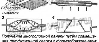
History of appearance
The history of friction stir welding (FSW) began in 1991. This was an innovative development of the British Welding Institute (TWI). A few years later, the technology was used in the construction of aircraft and ships.
The first companies to put the new technology into production were the Norwegian Marine Aluminum and the American Boeing. At their enterprises they used welding equipment from the ESAB concern, which specializes in developments in the field of rotary friction welding (FW).
Since 2003, the company has been continuously researching the possibilities of friction stir welding. For example, methods have been developed for welding aluminum alloys and their modifications used in the construction of aircraft, ships and railway containers.
In the aircraft industry, an opportunity was found to replace rivet joints with welded ones. Moreover, the speed of welding by the FSW method significantly exceeds the speed of electric arc. A weld seam 6 meters long can be formed in one minute, while the welding speed in the usual way reaches only 0.8-2 m/min with a part thickness of 0.5 cm.
The essence of the process
The joining of metals occurs due to heating in the welding zone using the friction method. The main welding tool for friction stir welding is a metal rod consisting of two halves: a collar and a shoulder.
With its protruding part, the rotating rod is immersed in the material, causing intense heating. Its supply is limited by the shoulder, preventing it from passing through the part being welded. In the heating zone, the material significantly increases its plasticity and, pressed by the shoulder, forms a single mass.
The next step is to move the rod along the welded zone. Moving forward, the collar mixes the heated metal mass, which, after cooling, forms a strong connection.
Areas of use
FSW is often used in many manufacturing fields. In rocket and aircraft construction, this technology is used to manufacture various panels and fuselage. As for shipbuilding, FSW in this area is used for welding structures of small ships. It allows you to make very strong connections. Welded seams after the FSW technique can withstand significant loads and are durable.
Friction welding joins metal alloys, which are not in a molten state, but in a solid state. For this purpose, special equipment is used, consisting of a profiled base, a collar and a tip with a metal profile, which moves along the joint of the workpiece. Then a large amount of thermal energy is released and the surfaces are subsequently joined.
Of course, everyone needs to see this process with their own eyes. This technique has many advantages that distinguish it from many other welding technologies.
Specialists in many fields of activity fell in love with STP because it is very convenient and easy to use. In addition, this method allows you to save time on preparatory activities.
What affects the quality of STP
Friction stir welding is a constantly evolving process. But now we can identify several parameters that affect the quality of the connection:
- The force generated by the tool.
- Welding head feed speed.
- Burt size.
- Circumferential speed of rotation of the rod.
- Tilt angle.
- Rod feed force.
Manipulation of welding characteristics allows the joining of dissimilar metals to be achieved. For example, aluminum and lithium. Lithium, due to its low density and high strength, can act as an alloying component of aluminum alloy parts, which makes it possible to use this technology in the aerospace industry.
Friction stir welding can easily replace forging, stamping, and casting when they are used to produce parts from difficult-to-match metals. For example, steels with austenite and pearlite structures, aluminum or bronze steels.
In what areas is it used?
Industries such as the automotive industry are constantly working on how to increase the strength properties of a product while reducing its weight. In this regard, there is a continuous introduction of new materials that were previously unknown due to the complexity of processing. Increasingly, power elements such as subframes, and sometimes entire bodies, are made of aluminum or its combination with other materials.
Thus, in 2012, Honda used additive technologies and friction stir welding to produce subframes for its cars. They introduced a combination of steel and aluminum.
When producing welded aluminum body elements, burning of metal sheets may occur. STP does not have this drawback. In addition to the fact that electricity consumption is reduced by 1.5-2 times, the costs of consumables, such as welding wire and shielding gases, are reduced.
In addition to automobile production, STP is used in the following areas:
- Construction production: aluminum support trusses, bridge spans.
- Railway transport: frames, wheeled bogies, wagons.
- Shipbuilding: bulkheads, structural elements.
- Aircraft construction: fuel tanks, fuselage parts.
- Food industry: various containers for liquid products (milk, beer).
- Production of electrical equipment: electric motor housings, parabolic antennas.
In addition to aluminum alloys, friction stir welding is used to produce copper compounds, for example, in the production of copper containers for the disposal of spent radioactive fuel.
Advantages of STP
The study of FSW made it possible to select welding modes when joining different groups of alloys. Despite the fact that FSW was initially developed to work with metals with low melting points, such as aluminum (660 °C), it was later used to join nickel (1455 °C), titanium (1670 °C), iron (1538 °C ).
Research shows that the weld obtained in this way is completely consistent in its structure with the metal of the parts being welded and has higher strength indicators, lower labor intensity and low residual deformation.
A correctly selected welding mode guarantees compliance of the weld material and the metal being welded according to the following indicators:
- fatigue strength:
- bending and tensile strength;
- impact strength.
Types of FSW welding
This technology appeared at the end of the last century. At the moment, there are the following subspecies:
- Linear technique . With this option, the elements being processed rub against their surfaces until the conditions for a strong connection are formed. The movements during linear welding are reciprocating.
- Radial technique . This type of welding is often used for processing pipe structures. At the joint sections of the pipes there is a special ring, the rotation of which allows you to create the necessary temperature for joining the surfaces.
- Pin welding is often used in repairs . To do this, first create a hole into which a special pin is driven. After this, the part begins to rotate, thermal energy is generated, and plasticization of the coating occurs.
Advantages over other types of welding
STP has many advantages. Among them:
- Non-toxic. Unlike other varieties, there is no burning electric arc, due to which the molten metal evaporates in the welding zone.
- Increasing the speed of seam formation, thereby reducing production cycle time.
- Reduce energy costs by half.
- No need for further processing of the weld. The friction stir welding tool forms a perfect seam during operation and does not require stripping.
- There is no need for additional consumables (welding wire, technical gases, fluxes).
- Possibility of obtaining metal joints that are inaccessible to other types of welding.
- There is no need for special preparation of welding edges, with the exception of cleaning and degreasing.
- Obtaining a homogeneous weld structure without pores, as a result of which quality control, which is regulated for friction stir welding by GOST R ISO 857-1-2009, becomes easier.
Friction stir welding
New method of Friction Stir Welding (FSW) is by the effective method of receipt of high-quality connections of constructions of different geometry. In the article advantages of the method and influence of basic parameters of process on quality of the weld-fabricated guy-sutures are shown, examples of the executed works are made.
Friction stir welding (FSW) is a relatively new method for producing permanent joints of materials (patented by The Welding Institute in UK (TWI), (Great Britain)) in 1991 [1]. There is an earlier domestic author's certificate from the USSR for this welding method [2].
Research carried out in recent years has shown that FSW is an effective way to obtain high-quality connections of structures of various geometries, including sheet materials, spatial profile structures, pipes, restore worn parts, modify and improve the structure of materials, heal cracks and casting defects. Possessing wide technological capabilities for obtaining permanent connections between parts of assemblies, it can be used as an alternative to rivet connections, contact, seam electric arc, electron beam and laser welding, and welding of dissimilar materials. Thus, FSW becomes a universal technology that has great prospects in various industries [3]. According to the world's leading experts, this process is revolutionary in the field of welding sheet materials made of light alloys (aluminum and magnesium). This technology is considered key to the creation of fifth-generation aircraft. The thickness of sheet materials welded by FSW has reached 110 mm for aluminum alloys, and 45 mm for steel and nickel alloys.
It is necessary to note the following key advantages of STP
- Metallurgical and manufacturing: solid phase welding;
- low deformations of welded products;
- high dimensional stability and repeatability of the process;
- there is no “burnout” of alloying elements;
- high strength properties of the weld;
- fine-grained recrystallized weld structure;
- absence of shrinkage cracks;
- high welding speed;
- no additional heat treatment of the seam is required;
- wide range of materials to be welded.
- no protective gas environments required;
- low energy consumption (2.5% of the energy consumed in laser welding, 10% of the energy consumed in arc welding);
FSW is widely used in many industries. In aircraft rocket engineering for welding critical fuselage structures, tanks, panels for various purposes (NASA, Lockheed-Martin Corp., Boeing, Airbus Integrated Company, Wisconsin Center for Space Automation & Robotics, Oak Ridge National Laboratory, MTS Systems, State Research and Production Space Center named after M.V. Khrunicheva, etc.). In shipbuilding, FSW is used for welding the hulls of small ships, for example, the military boat Littoral Combat Ship is welded using the technology of Friction Stir Link, Inc.. FSW is the basic technology of Hitachi Rail Systems in the production of A-train railway cars and the Japanese high-speed train (Shinkansen) . I have experience in pipeline welding. Specialized equipment for FSW is produced by MTS Systems Corporation, Nova-tech engineering inc.. Friction Stir Link, Inc. (USA), Danish Stir Welding Technology (DanStir) (Denmark), ESAB (Sweden), Osaka East Urban Area, Osaka Cast and Hitachi (Japan), TWI (England), etc.
Work on FSW is carried out and supervised by The Welding Institute in UK (TWI) (UK), NASA, Lockheed-Martin Corp., Boeing, Wisconsin Center for Space Automation & Robotics, Oak Ridge National Laboratory MTS Systems Corporation, Thompson Friction Welding (USA) , Imhof Hartchrom GmbH and Klaus Raiser GmbH (Germany), Hidetoshi Fujii and JWPI Research Center at Osaka University (Japan), Shanghai puda friction welder co., ltd. (China) and other corporations and companies.
The expanding use of friction welding is due to the high quality of the resulting welded joints. Mixing metal in the solid phase under conditions of “warm” deformation sometimes creates microstructures that are stronger than the base material. Typically, the tensile and fatigue strength of the weld is 90% of the base material at the level achieved by the use of expensive electron beam, diffusion and laser welding. Friction welding can be performed in various positions (vertical, horizontal, inclined, bottom up, etc.) since gravity does not play a role in this case. Provides the ability to weld dissimilar materials, thermoplastic plastics and composite materials. When performing welding operations, no preliminary cleaning of working surfaces is required, there is no spattering of molten metal, and there is no need for filler materials. It is important that with special equipment and tools, friction welding can be performed on conventional metal-cutting equipment, universal milling machines and CNC machines, as well as using robotic systems. All other things being equal, compared to traditional arc and contact welding processes, FSW has energy consumption 2...5 times less. These factors determine that the use of STP increases annually by 15...20%.
Currently, Russian organizations have accumulated experience in friction stir welding of various aluminum alloys. Such studies in laboratory conditions were carried out at the Federal State Unitary Enterprise Central Research Institute of CM "Prometey", Federal State Unitary Enterprise "VI-AM", MSTU named after. N.E. Bauman, State Research and Production Space Center named after M.V. Khrunichev. FSUE NPO Tekhnomash, OJSC VNIIALMAZ, CJSC Sespel, etc. They confirmed the high efficiency of STP. At this stage, the main task is to create and organize the production of universal and special equipment and tools. Unfortunately, industrial equipment for FSW is not produced in our country.
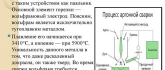
Friction stir welding is a process of joining materials in a solid state, in which a special rotating tool, structurally consisting of a flat or profiled base (collar) and a tip with a different profile (pin) located on it, moves along the joint surfaces of the parts being welded (Fig. 1) . The friction of the collar and pin in contact with the material being welded causes heat generation, due to which the material softens. The friction process during FSW is accompanied by plastic deformation of thin near-contact layers in which internal friction occurs. The main functions of the pin are to mix and transfer material by extruding it between the surface of the tool and non-softened material, and the collar is to create excess pressure in the welding zone. The pressure of the tool shoulder in the joint zone causes plastic deformation and flow of the plasticized metal, mixed with a profiled tip. Thus, the connection is carried out under extrusion conditions with forging of the material at high rates of relative deformation.
Fig. 1 Scheme of friction stir welding
The friction forces and the stress state of the deformed volume of the material depend on the patterns of changes in the physical and mechanical properties of the materials being welded during the FSW process, determined by such factors as temperature, degree and rate of deformation, tool geometry and technological modes.
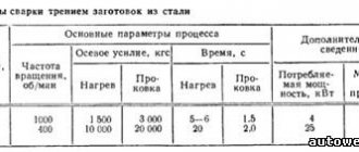
The main parameters of the FSW process are
1. Force acting on the tool during the welding process
It is customary to decompose it into components (Fig. 1) in the Cartesian coordinate system:
| Fx | — | force acting in the direction of welding (along the seam); |
| Fy | — | a force acting perpendicular to the direction of welding in a plane parallel or tangential (when welding curved surfaces) to the surfaces of the joined elements (welding plane); |
| Fz | — | force acting in a direction perpendicular to the welding plane. |
It is obvious that the magnitudes of the acting forces depend on the materials of the workpieces being welded, the temperatures in the welding zone, the welding speed, the geometry of the welding tool and its orientation (inclination) relative to the welding plane. All other things being equal, the force values increase with decreasing temperature and increasing welding speed. High force values can lead to tool destruction.
2. Welding speed, V
St.
Determined by the speed of movement of the tool in the direction of welding. Low welding speeds can lead to overheating of the material, changes in the conditions of thermomechanical action, an increase in the heat-affected zone and, as a result, a decrease in the strength characteristics of the welded joint.
3. Tool rotation speed
Rotation of the tool ensures heating of the material by heat generation during friction and its transfer during the movement of the tool along the seam from the front to the rear part of the welding zone. Increasing the tool rotation speed increases heat generation and intensifies material transfer and mixing. If the material is not sufficiently heated, then free spaces may form behind the pin, leading to discontinuity in the seam; in addition, large forces act on the tool, which can lead to its destruction. On the other hand, an increase in temperature above a certain limit leads to defects caused by overheating of the material (Fig. 2).
Fig. 2 Zones of FSW modes: 1 – high loads on the tool, defects in the form and lack of fusion due to insufficient heating; 2 – area of optimal welding conditions; 3 – difficulty maintaining welding conditions, a promising area of welding modes that provides high productivity (high-speed FSW); 4 – overheating of the metal and deterioration of its structure, formation of scoring and seizure with the tool, deepening of the tool
4. Tool inclination angle, α
To improve the conditions for forming a welded joint, the tool can be inclined relative to the perpendicular to the welding plane. Typically, such an inclination is made at an angle of 1.5...4.5° in the direction of welding, ensuring a lower position of the edge of the collar behind its zone. The inclination of the tool helps to improve the conditions for forging the seam with a shoulder. If the angle of inclination is too small, this can lead to the formation of defects in the form of lack of fusion on the outer surface of the seam, and if the angle of inclination is too large, the continuity of the seam at the root may be disrupted with the formation of a tunnel defect.
5. Tool shoulder immersion depth
Defined as the distance from the surface of the workpiece to the lower position of the end of the collar. Practically important are the depth of penetration of the collar and the position of the end of the pin at the root of the weld. The immersion depth must provide conditions for forging the seam over the entire thickness of the material being welded and preventing the formation of defects. Insufficient penetration of the tool shoulder into the material being welded leads to an increase in the volume that must be filled with plasticized metal when forming a seam, and, as a consequence, to a decrease in excess pressure and the formation of discontinuities in the seams. In addition, an amount of heat is released that is insufficient to ensure the required level of plasticization necessary for high-quality formation of the seam, and defects in the form of lack of penetration are formed on the front surface of the seam.
6. Tool geometry
The quality of friction stir welding and its productivity are largely determined by the geometry of the welding tool. The geometry parameters of the tool, consisting of a pin and a shoulder, must not only ensure the quality of the welded joint, creating the required conditions for thermoplastic deformation and mass transfer, but also its durability, strength, and the minimum force of tool penetration when inserting it into the welded joint. The tool material must have high heat resistance, hardness and heat resistance, wear resistance, and low thermal conductivity. This particularly applies to tool materials intended for welding steels, titanium and nickel alloys, etc. To improve the quality characteristics of tools, surface hardening and coating technologies are sometimes used. Special profile cuts are made on the pin and shoulder surfaces to control the flow of the plasticized material. The shape of the collar can be flat, concave or conical. For FSW welding tools can be used with a rotating shoulder, with a stationary shoulder, reel (Fig. 3), with a conical pin, with a variable pin length, without a pin.
Fig. 3 Scheme of “reel” FSW: 1 – workpiece; 2 – upper shoulder; 3 – force regulation device Fz; 4 – pin; 5 – lower collar
Some typical designs of welding tools are shown in Fig. 4.
Fig.4 Working parts of tools for FSW
During friction stir welding, the welding tool experiences intense heat and force, which limit its service life; changing the shape of the working part of the tool leads to disruption of the stability of the welding process. It should also be noted that the penetration of tool wear particles into the material being welded can adversely affect the quality of the welded joint.
For welding, tools made from the materials listed in Table 1 are used.
Table 1
| Material to be welded | Thickness, mm | Tool material |
| Aluminum alloys | <12 | Tool steels, hard alloys of the WC-Co system |
| >12 | Cobalt-nickel alloys (MP 159)* | |
| Copper and copper alloys | <50 | Nickel alloys, cubic boron nitride (CBN), tungsten alloys |
| Titanium alloys | <6 | Tungsten, tungsten-rhenium alloys |
| Stainless steels | <6 | CBN, tungsten alloys |
| Low carbon steels | <12 | Hard alloys of the WC-Co system, CBN |
| Nickel alloys | <6 | KNB |
| * MP 159 is a multiphase alloy having a unique combination of strength (1600 MPa), toughness (* = 12%), high-temperature strength and heat resistance. The alloy is produced by vacuum induction melting with control of the solidification process. Retains high strength up to a temperature of 650 C. Composition of MP 159: Al – 0.20%; Cr – 19.0%; Co – 35.7%; Fe – 9.0%; Mo – 7.0; Ni – 25.5%; Nb, Cb – 0.60%; Ti – 3.0%. | ||
7. Preheating or cooling
It is advisable to preheat the welding zone for materials with relatively high melting temperatures, such as steels, titanium alloys, etc. in order to reduce the acting forces and increase the durability of the tool, speed up the heating process and increase the welding speed. Typically, induction heating is used for these purposes.
Cooling of the welding zone is performed for aluminum and magnesium alloys, primarily to reduce grain growth. Cooling is performed by air flow. In addition, FSW can be performed in water.
Figures 5 and 6 show characteristic cyclograms of STP.
Fig.5 Typical cyclogram of friction welding, reflecting changes in operating parameters: 1 – tool penetration value h; 2 – tool rotation speed n; 3 – welding speed V
Fig.6 Typical cyclogram of friction welding, reflecting the nature of the change in force parameters: A – tool penetration; B – pause; B – movement along the seam; G – tool outlet; 1 – normal (axial) force Fz; 2 – torque value; 4 – resistance force to movement in the welding direction Fx
In most cases, four different zones can be distinguished in the weld zone (Fig. 7): the mixing zone, the thermal-deformation zone, the heat-affected zone and the base material.
Fig.7 Formation of a seam during FSW, indicating the zones in its cross-section: A – base material; B – thermally affected zone; C – zone of thermal deformation influence; D – mixing zone
The mixing zone has fine equiaxed grains. This structure is formed as a result of recrystallization under the action of intense plastic deformations and high temperatures. The macrostructure of the mixing zone sometimes has a so-called “onion-shaped” shape (Fig. 8), which consists of characteristic rings. The mechanism for the formation of such a structure is associated with the extrusion of the material in a narrow space between the tool and the material not softened by heat generation. Many researchers believe that the “onion” structure is a sign of high quality welded joint [4].
Fig. 8 “Onion-shaped” macrostructure of the mixing zone
The thermomechanical influence zones are located on both sides of the mixing zone. Plastic deformation and temperature in these zones are lower than in the mixing zone. The consequence of this is the formation of a structure with areas of small and relatively large grains, since this zone is only partially recrystallized.
In thermally affected zones, grains are large in size, since their material is exposed only to elevated temperatures in the absence of plastic deformation, which is accompanied by grain growth, the material in this zone has the lowest strength properties.
Using FSW it is possible to obtain various types of welded joints (Fig. 9).
Fig. 9 Welded joints obtained by FSW
It should be noted that FSW can be performed with filler material, with additional heating, with the use of inert and alloying media, with mechanical and strengthening treatment of the weld.
Based on FSW, technologies for various purposes have been developed: seam welding, spot welding, surfacing, elimination of material defects and its modification, formation of internal channels, soldering, building up material (additive technology), etc.
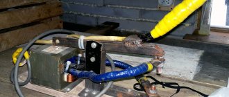
Figures 10...17 show examples of welding performed at OJSC VNIIALMAZ and photos of the installation for FSW.
Fig. 10 Friction stir welding of structural steel samples using a cubic boron nitride tool
Fig. 11 Structural steel specimen bent after friction welding
Fig. 12 3-Model and elements of panels made of aluminum alloy 1163 RDTV, welded by FSW
Fig. 13 Tubular parts from homogeneous and dissimilar materials, welded by FSW
Fig. 14 Welding sheets of aluminum alloy and copper
Fig. 15 Element of a pipe welded by FSW
Fig. 16 Samples of titanium alloy VT20 and steel 12Х18Н10Т, welded by spot FSW
Fig.17 Installation for high-speed friction stir welding
Literature
- W. M. Thomas et al., 1991. US Patent No. 5,460.31 7.
- A. S. USSR 1195846, Cl. IPC B 23 K.
- Influence of process parameters of friction stir welding on the formation of welds in joints of aluminum alloys with a thickness of 1.8...2.5 mm / Poklyatsky A. G., Ishchenko A. Ya., Podelnikov S. V. // Automatic welding. – 2008. – No. 10. – P. 27-30.
- By Rajiv S. Mishra, Murray W. Mahoney: Friction stir welding and processing, ASM International. ISBN 978-0-87170-848-9. 352 rub.
- Krishnan, K. N. “On the Formation of Onion Rings in Friction Stir Welds.” Materials Science and Engineering A 327, no.2 (April 30, 2002): 246-25 1. doi:10. 1016/S0921-5093 (01)01474-5.
How is the quality of a weld seam checked?
The quality of welding is checked by two types of control. The first involves the destruction of a prototype obtained by joining two parts. The second allows verification without destruction. Methods such as optical control and audiometric examination are used. It helps to determine the presence of pores and heterogeneous inclusions that impair the characteristics of the seam. The results of sound monitoring are a diagram that clearly shows where the acoustic echo deviates from the norm.
Disadvantages of the method
Despite its many advantages, the friction welding method has accompanying disadvantages:
- Lack of mobility. FSW involves the connection of fixed parts that are rigidly fixed in space. This imposes certain properties on friction stir welding equipment, such as immobility.
- Low versatility. Bulky equipment is configured to perform the same type of operations. In this regard, welding fixtures are designed for specific tasks. For example, for welding car sides on a conveyor belt, and for nothing else.
- The weld seam has a radial structure. In this regard, with certain types of deformation or when the part is operating in an aggressive environment, weld fatigue may accumulate.
Principles of Using Friction for Connections
This process means that what one does during its rotation will create thermal energy, as a result of which the materials will join with each other. But not only one of the parts can rotate, but also a special tool for friction stir welding in the form of an insert, which also contributes to the high-quality connection of parts. The surfaces are pressed against each other gradually or using constant pressure.
When welding is completed, settlement occurs and the part quickly stops rotating. The joining zone is characterized by processes such as rubbing of contact surfaces against each other as a result of increased pressure on the parts and an increase in the rotational speed of the material. The fatty films that are on the workpieces in the initial state will be destroyed, after which the boundary friction will change to dry. Certain small protrusions will come into contact and begin to deform.
The entire connection process can be divided into several stages:
- Oxidized films are removed using friction;
- Heating the surface to be welded to a melting state;
- The appearance and destruction of temporary contact;
- The most flexible parts of the material are removed from the joint;
- Completion of the process and formation of a monolithic welded joint.
Advantages of friction joining
STP has quite a lot of advantages, both from the production and metallurgy side, and from the energy, economics and ecology side, let’s look at each of them in more detail:
- With friction welding, it is always possible to achieve a high quality welded joint zone. But this always depends on the experience of the specialist and the correct choice of welding mode. The resulting seam will always have no pores, other defects, and the metal itself in the joint zone will have a homogeneous structure;
- Productivity is at a high level. The thickness of the layer that is heated as a result of friction is small, so the entire welding procedure does not take much time, usually from a few seconds to one minute. This will depend on the material of the parts and their cross-section. Thus, the connection can compete in performance even with electric butt welding;
- Friction stir welding implies improved weld quality characteristics on a permanent basis. If the same joining mode is used for all metals, it will have similar properties to each other. This is the bending angle, temporary resistance indicators, impact strength, as well as other indicators that will differ from one another by only 7-10%. As a result, it is possible to apply selective control of the final quality; it will play a very important role, since cheaper and simpler methods of monitoring connections that will not violate their integrity are largely absent in welding shops;
- Increased energy efficiency. A high level of efficiency provides heat that is generated locally, in limited volumes, this allows reducing energy costs by almost 10 times when compared with butt resistance welding;
- When friction welding, there are no special requirements for preparing and cleaning the surface to be welded. This will save time on the welding process as a whole;
- With a fully automatic welding mode, the result will be of the same quality, and the process itself will not create any difficulties for the specialist;
- There is always the opportunity to weld various types of metals. This applies to both homogeneous alloys and dissimilar metals, which distinguishes FSW from other joining methods, which in such a situation will not bring a positive result;
- During friction, ultraviolet radiation is not emitted, which has a positive effect on the hygiene of the process. There is also no splashing or release of other harmful gases.
Flaws
Despite all the above advantages, welding can also have a downside, which has certain disadvantages:
- The equipment can be inconvenient and cumbersome. This process is not very flexible and involves the use of stationary machines. If we are talking about welding a small workpiece to a massive part, it will become impossible to carry out such an operation using a portable device;
- The process has low versatility. This means that you must always take into account the peculiarity of such a connection, in which one of the parts must necessarily rotate. And the second must have an appropriate plane and be stable. But this cannot be fully called a disadvantage; it is only a specific principle that is characteristic of this method of connection;
- The textured fibers of the part in the welding zone may be subject to deformation. In the joining zone, the fibers are arranged radially and extend to the outer part of the material. Therefore, if the part is used in an aggressive environment or with constant loads, there is a possibility of corrosion or fatigue failure.
Kinds
This friction stir welding method was invented back in 1991. After which its subspecies appeared. These include:
- Linear friction welding. With this method, rotation of parts is not used for connection. This is the main difference between this method and the others. The parts to be joined rub against each other until the required environment for a strong connection is formed. One of the workpieces will perform reciprocating movements, and the pressure will allow the required connection to be achieved.
- Radial welding. This type is appropriate for connecting pipe structures. At the joints of the pipes there is a special ring, which, when rotated, forms the required heat indicator for connecting the surfaces.
- Pin welding. It is mainly used for repair work. First you need to drill a hole and guide a pin made of the appropriate material into it. It then rotates, generating heat and plasticizing the surface, which makes it possible to obtain a strong connection between the workpieces.
Types of STP according to the operating principle
Welding processes that rely on friction can be divided into several types:
- Linear friction. The essence of the method comes down to obtaining a permanent connection not as a result of the action of a rotating tip, but due to the movement of parts relative to each other. By acting on the surface at the point of contact, they create friction and, as a result, high temperature. Under pressure, the adjacent parts melt and a welded joint occurs.
- Radial welding. This method is used for the production of large-diameter containers and railway tanks. It comes down to the fact that the joints of the parts are heated by a rotating ring, dressed on the outside. By frictional force it causes a temperature close to the melting point. An example of an enterprise using this technology is the Cheboksary company for the production of Sespel tanks. Friction stir welding occupies the main share of welding work.
- Pin welding. This type replaces the rivet connection. This type is used for overlapping joints. A rotating pin at the point of contact heats up the parts being welded. The high temperature causes melting and the pin penetrates inside. Once cooled, it creates a strong, permanent connection.
Welding principle
Friction welding of metal is a technological process for manufacturing a welded joint, which is carried out through the use of thermal energy arising on the contact surfaces of the elements being connected. During this process, the elements are pressed against each other with force, and one of the workpieces moves relative to the other.
Typically, rotational friction is applied, during this process one of the workpieces being welded or a tab between the elements rotates. At the point at which the elements are intensely pressed, heat is released and heating occurs.
Due to high temperature and friction, active destruction of oxide films and traces of foreign contaminants occurs. The surfaces of the welded elements are tightly rubbed against each other, during which the destruction of micro protrusions begins. The surface becomes smooth, and due to this, metal atoms can fully interact with each other.
Friction welding is carried out in several stages:
- removal of oxide films;
- heating surfaces to achieve a state of plasticity. During this stage, fragments of crystal lattices are also created and destroyed;
- at the third stage, the rotation stops, crystallization of the contact zone occurs and a welded joint is formed.
After the required melting temperature is reached, the rotation stops with a simultaneous increase in the pressing force.
Types of STP by level of complexity
Welding operations performed using friction can be divided into planar and volumetric. The main difference between these varieties is that in the first case the welding seam is formed in two-dimensional space, and in the second in three-dimensional space.
Thus, for planar joints, the welding equipment manufacturing company ESAB has developed a 2D LEGIO installation. It is a customizable friction stir welding system for a variety of non-ferrous metals. Different size groups of equipment allow you to weld parts of small and large sizes. According to the marking, LEGIO equipment has several layouts that differ in the number of welding heads and the ability to weld in several axial directions.
For welding work with complex positions in space, there are 3D robots. Such devices are installed on automobile conveyors, where welds of a complex configuration are required. One example of such robots is the Rosio installation from ESAB.