Scope of application and features
Processing materials on a lathe involves securing a cylindrical workpiece into a three-jaw chuck. Due to the perpendicular feed of the cutting tool, the specified thickness of the metal is removed. All this allows you to grind the workpiece to the required size.
When performing certain jobs, simply fixing the workpiece in the chuck is not enough. To ensure safety, obtain the required cleanliness and accuracy, additional support of the part by the tailstock is required.
In what cases is it necessary to use a rotating center:
- The length of the workpiece is 5 times the diameter.
- Turning of heavy parts at high speeds (high speed and feed).
- Large thickness of chips removed.
- When finishing will take place on a grinding machine.
Features and benefits of using centers:
- Long service life.
- Resistance to high loads.
- Possibility to increase processing speed.
- Improving equipment performance.
- Versatility - can be used on manual machines and CNC equipment.
- High quality parts.
You might also be wondering how to properly mount a DRO on a lathe?
The disadvantages of the device include radial runout. If, according to technical requirements, this error is unacceptable, finishing is practiced using a fixed center in gentle modes.
Node purpose
The tailstock of a metal lathe is a reliable support for securing the workpiece. In addition, it supports the second edge of the workpiece and ensures its stable rotation. During drilling, it is connected to the support with a grip. A drill of the required diameter is inserted into the quill chuck. In addition to drills, mounting is provided for: dies, taps, reamers, countersinks and other cutting tools. Such a wide range of tools used allows for a wide range of processing operations.
Price
| Type | Lathe | Type of work | Landing | Price, rubles |
| Fixed | JET | MK-3 | 500 | |
| Rotating | JET | MK-2 | 1800 | |
| Rotating | JET | MK-5 | 3000 | |
| Rotating | JET | for medium work | MK-3 | 2000 |
| Rotating | JET | for light work | MK-2 | 2800 |
| Rotating | JET | for heavy work | MK-5 | 3000 |
| Rotating | Tekhosnastka-S BT-5592 | for processing parts with center holes | A-1-3-N | 2050 |
| Rotating | Tekhosnastka-S BT-5598 | for processing parts with center holes | A-1-6-U | 11500 |
Design of rotating centers
The rotating center consists of a shaft and a conical tip. It is the working part that fixes the part. Rotation is ensured by a built-in ball bearing. It increases the efficiency of equipment, reduces friction and heating.
The standard tip angle is 60º. Such equipment is used in most cases when processing is carried out in standard modes. To work with heavy parts, a center with a tip angle of 90º is required.
The diameter of the tapered shank may vary depending on the tool model. To install the device in the tailstock, you will need a Morse taper 5.
Centers for lathes
The design of lathes requires the use of certain equipment. Only if you have the necessary equipment can you make a part with the required accuracy parameters. In this case, you need to purchase special equipment or make a homemade version. It is worth noting that you cannot create everything for precision turning with your own hands.
Turning rotary centers
Fixing workpieces
Turning on a lathe occurs by mounting it in a jaw chuck, which transmits rotation and at the same time holds it in place. Such a device is effective when turning cylindrical bodies. In this case, the cutter is fed perpendicularly, which allows the metal to be machined to the desired diameter.
When considering a metal lathe, keep in mind that many homemade and commercial versions have a structure at the back to support the workpiece and perform other tasks. A homemade type of metal lathe also has a headstock version, which requires special equipment.
Thus, when fixed on two opposite sides on the lathe, the tailstock and the headstock, the workpiece will be in the specified position during even heavy loads.
When considering the tailstock, the following features should be noted:
1.
The device in question is intended only for attaching special equipment. The types of equipment used on a lathe determine the purpose of the tailstock: it can serve both for fixing a cylindrical body and for processing.
2.
To ensure that the workpiece does not change its position at the time of strong feed or at high speeds, the center is used, which determines the purpose of the tailstock.
3.
You can make the center yourself or purchase it at a specialized store. When making it yourself, you need to take into account that the workpiece must be solid solid metal with an increased strength index. This is due to the fastening method: the quill presses the part against the spindle at the end and throughout the entire time the tip is in contact with it, slight friction occurs.
4.
The position of the lathe quill is adjustable only in the longitudinal direction. Given this feature, it is worth remembering that the position of the center must coincide with the axis of rotation of the spindle. Otherwise, rotations will occur with beating.
The device in question can also be used for drilling end holes and solving other technological problems.
Fixation at two ends occurs in the following cases:
1.
An industrial-type metal lathe has adjustable speed. The high rotation speed that is transmitted to the part leads to “wobble” of the part. With precision processing, according to GOST, this phenomenon leads to a fairly large error.
2.
The large length and weight of the workpiece also determines the need to use a tailstock. Under its own weight, the cylindrical body can be deformed and the cutter will “hit” the metal while feeding the cutter.
3.
Depending on the turning mode and spindle speed, excessive cross feed may occur. When processing a part in such a situation, it is quite difficult to make it with high accuracy.
In such cases, fixation should be carried out at both ends.
Types of turning centers
You can fix the necessary tool in the quill yourself. This job will take a few minutes to complete, and you can do it yourself. According to GOST, the following types can be distinguished:
1.
persistent. GOST determines that the tip and shank have almost the same diameter. The device of this design determines that the tip is made of hardened steel or hard alloy in accordance with GOST 13214-79.
2.
the fungal version is somewhat different from the previous one. According to GOST 8742-75, the mushroom tip has a larger diameter with a truncated working cone. According to GOST 8742-75, there are two types of tips that the fungal center has: with a centered roller or with an attachment for it. The mushroom tip allows the device in question to be used for fastening rotating bodies with hollow end holes during processing.
Mushroom turning center
Rotating turning centers
Thrust rotating centers
When turning under high centrifugal force, the most favorable conditions can be achieved by using a center whose design includes a bearing. Such equipment can be different: the mushroom or thrust center also has a bearing. A large selection of turning centers is presented on the website https://meatec.ru/catalog/tokarny-centry/.
The cone angle can be 60 or 90 degrees. The angle is selected depending on the cutting mode.
There are more complex types of equipment for installation in quills, which may have, for example, a device for measuring downforce. It is impossible to make some versions of centers for a lathe with your own hands. Reverse spindle motion does not affect the ability to use the quill.
Varieties
In turning, several types of rotating center are used. According to their purpose, equipment is divided into two types:
- Thrust center - the pointed tip rests against the end of the part. You must first make a centering hole.
- Fungal - has a tip of a larger diameter with a truncated cone. Used for fixing parts with an internal hole (pipes, hollow shafts).
By design:
- With permanent roller (type A).
- With replaceable nozzle (type B).
The use of type B allows you to use one device for processing products with different dimensions. Removable attachments make it easier for the cutter to approach the workpiece. Such equipment is often used when turning shaped parts.
Centers for lathes are made of high-strength alloy steel. Depending on the complexity of the process, they can be regular or enhanced. The latter are used when working with heavy products. Reinforced is durable and resistant to high loads.
Types of rotating centers
Depending on the shape of the fixing part, two types of rotating centers are available:
- with a working cone for fastening workpieces with center holes;
- with mushroom-shaped attachment for workpieces with an internal hole - pipes, hollow shafts, etc.
By design, the equipment is divided into:
- Center with permanent roller (type A)
- Center with replaceable nozzle (type B)
The cone of the center roller is machined at 60° (version 1) or may have an additional groove for a 30° cone (version 2).
Symbol of equipment: Center A-1-4-NP GOST 8742-75
Type A, version 1 with Morse taper 4 of increased accuracy and normal series.
Table of basic equipment parameters
| Rotating machine centers GOST 8742-75 Type A - with permanent center roller Type B - with an attachment on the center roller | ||||||||||
| Center rotating type-version-Morse taper-series | d | D | L 1 row L 2 row | L 1 row L 2 row | D1 | l1 | ||||
| Rotating center A-1-2-N | Rotating center A-2-2-N | Rotating center B-2-N | 22 | 56 | 160 | 90 | 56 | 24 | ||
| Rotating center A-1-3-N | Rotating center A-2-3-N | Rotating center B-3-N | 25 | 63 | 180 | 185 | 94 | 99 | 63 | 26 |
| Rotating center A-1-4-N | Rotating center A-2-4-N | Rotating center B-4-N | 28 | 71 | 210 | 225 | 101 | 116 | 71 | 30 |
| Rotating center A-1-5-N | Rotating center A-2-5-N | Rotating center B-5-N | 32 | 80 | 240 | 260 | 104 | 124 | 80 | 34 |
| Rotating center A-1-4-U | Rotating center A-2-4-U | Rotating center B-4-U | 36 | 75 | 220 | 235 | 111 | 126 | 75 | 36 |
| Rotating center A-1-5-U | Rotating center A-2-5-U | Rotating center B-5-U | 40 | 90 | 250 | 275 | 114 | 139 | 90 | 45 |
| Rotating center A-1-6-U | Rotating center A-2-6-U | Rotating center B-6-U | 56 | 125 | 340 | 360 | 150 | 170 | 125 | 56 |
Specifics of operation
Before starting work, the turner must take into account runout errors. It occurs due to wear of the bearings or tip, or insufficiently rigid fixation. If the requirements do not allow such an error, it is better to use other equipment.
What nuances need to be taken into account when processing in centers:
- The axes of the spindle and center must coincide, otherwise there will be processing errors. When turning parts with a high accuracy class, allowances must be left for finishing.
- The clamping force should securely fix the workpiece, but not interfere with its rotation.
- When working at high speeds, lubricant must be used to reduce tip wear.
Important!
The runout of the rotating center leads to radial runout of the part relative to the axis. Further processing of the same workpiece on another machine may lead to misalignment.
If strong runout is detected, the conical tip must be ground with a special tool, which is attached to the tool holder. After checking with a template, if the result is satisfactory, you can begin metalworking.
Important!
When turning at high speeds, the center tip wears out and the center hole breaks. To extend the life of the equipment, the tip is treated with a protective lubricant.
Turning centers.
Section: LIBRARY OF TECHNICAL LITERATURE Short path https://bibt.ruBook contents Previous Next
To install and secure shaft blanks on the machine, the length of which exceeds the diameter by 5 or more times, turning centers are usually used. The ends of the shafts must have center holes to install them in the centers.
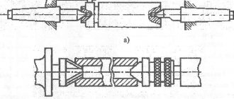
The designs of turning centers are shown in Fig. 46.
The rigid support center (Fig. 46, a) has a working part 1 with an angle of 60° at the apex. The tail part 2 has a small taper (Morse taper from 1 to 6). The center shank 3 has a diameter smaller than the smallest diameter of the tail cone, which eliminates jamming of the cone when the center is knocked out of the socket.
The center shown in Fig. 46, b, is used for installing small-diameter workpieces - up to 4 mm. For such workpieces, instead of center holes, outer conical surfaces are made with an angle of 60°, with which they are installed in hole 1 of the center. Such centers are called inverse.
The half-center, cutout 1 of which makes it possible to completely process the end of the workpiece, is shown in Fig. 46, v. Install the half-center only in the tailstock.
The center with spherical working part 1 is shown in Fig. 46, Center makes it possible to install workpieces with some misalignment of the workpiece axis to the axis of the machine centers.
The grooved working surface of the center shown in Fig. 46, d, makes it possible to process workpieces with a large center hole without a driving chuck.
Rice. 46. Turning centers
A conventional, or rigid, support center is used at a relatively low spindle speed (up to 120 rpm), since friction occurs between the workpiece and the working cone of the center, which can lead to rapid heating and wear of the center.
Work with an increased spindle rotation speed is carried out on wear-resistant centers, in which a layer of hard alloy is fused onto the working cone or a hard alloy tip is soldered in (Fig. 46, e).
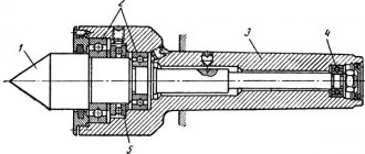
Operation at high rotation speed necessitates the installation of a rotating rear center (Fig. 46, g). The center spindle 1 is installed in bearings 2, 3, 5 located in housing 4.
To reduce friction between the workpiece and the rear center, a center with constant lubrication is used (Fig. 46, h). When installing the shaft, the conical surface of its center hole presses on the slightly protruding end of the plunger 2 with spring 3 and oil from the oiler 1 through channel 6 of the housing 4 and groove 5 flows to the rubbing surfaces.
External surfaces with a large center hole can be machined using the front center with a grooved surface on the work body.
Skip to navigation