Semi-automatic device
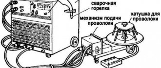
Before you start assembling a semi-automatic device, it is important to clearly understand its structure and operating principle. In simple words, a semi-automatic machine consists of two blocks: a power block (power part) and a feed block (feeding mechanism). Let's talk about them in more detail.
You probably already know that semi-automatic welding uses a special filler wire, which plays the role of an electrode. It is a kind of conductor of current into the welding zone and allows the formation of a seam. If there is wire, then it must somehow be fed into the welding zone. This, of course, can be done manually (literally feeding the rod into the weld pool using your hands), but it is more advisable to use a special feeding mechanism. Usually it is built inside a semi-automatic machine, but in home-made units it is often free-standing.
The power unit operates on the basis of an inverter, which acts as a current source. It is also free-standing in the case of a homemade semi-automatic machine.
These are the main components. In addition to them, you will need a torch, a hose (also known as a welding sleeve), a nozzle and other elements necessary for working with gas.
Electrode wire feeding mechanism
a case from a computer system unit is ideal for this purpose.
. Plus, there is no need to throw away the power supply. It can be adapted to the operation of the broaching mechanism.
To begin with, you need to measure the diameter of the coil of wire or, having outlined it on paper, cut out a circle and insert it into the body. There should be enough space around the reel to accommodate other components (power supply, hoses and wire pulling mechanism).
The wire drawing device is made from a windshield wiper mechanism from a car.
It is necessary to design a frame for it, which will also hold the pressure rollers. The layout must be drawn on thick paper in real scale.
Advice! The connector for connecting the burner hose and the hose with the burner itself can be made with your own hands. But it would be better to buy a ready-made kit that has an affordable price.
The feeder should be installed in the housing so that the connector is located in a convenient location.
In order for the wire to be fed evenly, all components must be fixed exactly opposite each other. The rollers must be centered relative to the hole for the inlet fitting, which is located in the connector for connecting the hose.
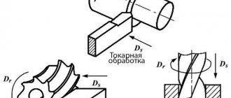
can be used as roller guides .
A small groove is machined on them using a lathe, along which the electrode wire will move. For the mechanism body, you can use 6 mm thick plywood, textolite or durable sheet plastic. All elements are fixed to the base, as shown in the following photo.
A bolt drilled along the axis is used as the primary guide for the wire.
. The result is something like a wire extruder. At the inlet of the fitting, a cambric reinforced with a spring (for rigidity) is put on.
The rods on which the rollers are attached are also spring-loaded. The clamping force is set using a bolt located below, to which the spring is attached.
Advice! If for some reason you do not have the opportunity to make a mechanism for drawing wire with your own hands, then you can buy it in China. 12 V and 24 V mechanisms are available for sale. In this case, since a power supply from a computer is used, you will need a device powered by 12 V.
Base for securing the bobbin
can be made from a small piece of plywood or PCB and a piece of plastic pipe of suitable diameter.
Principle of operation
To understand the operating principle of a standard semi-automatic machine, you do not need to have deep knowledge in the field of physics and chemistry. After all, the principle is quite simple and understandable even for a beginner.
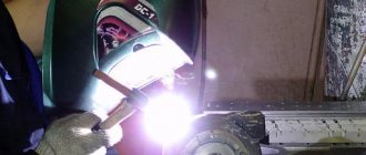
The welder, starting welding, directs the torch to the welding zone. At the same time, the welding wire is fed in a semi-automatic mode (the wire is threaded into the torch, so during the process you will only have one hand occupied, which is very convenient). A jet of shielding gas is supplied along with the wire. A discharge is formed between the wire and the workpiece in the gas mixture, causing the metal to melt. It is then mixed with the molten wire and the welder can begin to form the weld. The technology is simple and straightforward, and all you need to do it is a gas cylinder and a wire. The gas protects the welding zone from oxidation, and the wire helps to form a high-quality seam.
Selection of consumables
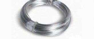
Let's talk a little about the consumables that we mentioned above. When selecting wire, you need to pay attention to two characteristics: diameter and composition. The diameter of the wire should be equal to the thickness of the metal you will be welding. And the composition must match the composition of the same metal.
Now about gas. Various gases can be used for welding, but our homemade machine will be designed for welding with carbon dioxide. You will be able to cook without gas if you replace regular wire with cored wire. Flux cored wire is not entirely metal, its core consists of flux. When the wire melts, the flux is released and forms vapors, which act as protection against oxidation. But we do not recommend using flux-cored wire all the time, since it does not provide high-quality seam formation. This technology is more suitable for hard-to-reach welding than for everyday work.
We believe that the optimal set of consumables for home welding is a gas cylinder with carbon dioxide and ordinary metal wire, selected in accordance with the parameters of the part. By the way, you don’t have to buy huge 40 liter cylinders. There are cylinders of 10 liters and even 5 liters on sale. You can put them in the trunk of your car and take them to your summer cottage yourself, without having to worry about transportation or ordering a cylinder from third-party companies.
Next, we will tell you how to assemble a semi-automatic welding machine with your own hands at home and whether it is worth doing this at all, or is it more advisable to buy a machine in a store. First things first.
Mechanical control circuit
To achieve good quality seam when welding, it is necessary to ensure wire feed at a certain and constant speed. Since the motor from the windshield wiper is responsible for the feed speed of the equipment, a device is needed that can change the speed of rotation of its armature. For this, a ready-made solution is suitable, which can also be purchased in China, and it is called
Below is a diagram from which it becomes clear how the speed controller is connected to the engine. The controller regulator with a digital display is located on the front panel of the case.
Next, you need to install a relay that controls the gas valve
. It will also control the engine start. All these elements must be activated when the start button located on the burner handle is pressed. In this case, the gas supply to the welding site should be ahead (by about 2-3 seconds) of the start of wire feeding. Otherwise, the arc will ignite in the environment of atmospheric air, and not in the environment of the protective gas, as a result of which the electrode wire will melt.
A delay relay for a homemade semi-automatic machine can be assembled based on an 815 transistor and a capacitor
. To get a pause of 2 seconds, a capacitor of 200-2500 uF will be enough.
Advice! Since the power comes from a computer power supply, which produces a voltage of 12 V, instead of making the module yourself, you can use a car relay.
It is placed in any place where it will not interfere with the operation of the moving units, and is connected to the circuit according to the diagram. You can use an air valve from GAZ 24 or buy a special one designed for semi-automatic machines. The valve is responsible for the automatic supply of protective gas to the burner. It turns on after pressing the start button located on the semi-automatic burner. The presence of this element significantly saves gas consumption.
But as already noted, the current-voltage characteristics (CV) of the inverter are not suitable for full-fledged operation of a semiautomatic device. Therefore, in order for a semi-automatic attachment to work in tandem with an inverter, minor changes need to be made to its electrical circuit.
DIY semi-automatic
Below is a video on how to make a semi-automatic welding machine with your own hands. The author provides a fairly detailed description of his homemade semi-automatic machine based on an inverter for MMA welding. The basis of such a homemade semi-automatic machine is a welding inverter for manual arc welding. The author assembled the feeding mechanism literally from scrap materials. At the same time, many components can be bought inexpensively on the Internet and you don’t have to bother making them yourself. It is not practical to make the same welding sleeve for a semi-automatic machine yourself; it is much easier to order it at a low price.
Below is a diagram of semi-automatic welding and a control diagram for a semi-automatic welding machine.
Cart
The cart can be made by yourself. The use of ready-made structures is also permitted. You can make single-level, two-level and three-level products. For convenience, tools and materials that will be needed for work are stored on the upper level. For easy movement, the cart includes wheels with a diameter of at least 5 cm.
Homemade cart with several variations:
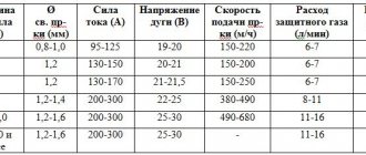
Welding modes in carbon dioxide:
A semi-automatic device differs from a conventional device in its wire feed mechanism. Therefore, such a unit is considered the most complex device. Repair will be necessary if the feed mechanism breaks down.
Another useful manufacturing option
Feasibility of manufacturing
Some may wonder whether it is even worth taking on such a painstaking task and assembling a homemade semi-automatic machine when you can buy it in a store and not waste time. This is a reasonable question. We propose to list in order all the reasons why you should make your own semi-automatic and in which cases it is inappropriate.
Let's start with the price. The cost of a good-quality semiautomatic device that will serve you for years is at least $300-400. And this is not counting all the related components, such as a burner, gas cylinders, wire, etc. Are you ready to shell out a large amount of money for a device that you will not use regularly? In our opinion, assembling a semi-automatic welding machine with your own hands is more logical. It's better to invest in a quality torch, a good mask and filler material.
The savings when making a homemade device is to use an inexpensive inverter. All you need from it is more power, since the device will be used as the “heart” of the future semi-automatic device. For these purposes, you can buy a used inverter for ridiculous money and convert it into a semi-automatic device.
Also, homemade semi-automatic welding machines, the diagrams for which are publicly available on many forums, develop your skills in assembling and making homemade electrical appliances. Surely after the semi-automatic machine you will want to do something else, since this process is quite interesting.
There are several reasons why you should not assemble a homemade semi-automatic welding machine.
The first is the lack of warranty. When you buy a device in a store, you receive a warranty card, with which you can have your semi-automatic machine repaired free of charge at a service center. This way you save not only energy, but also time. Time is the second reason. You are unlikely to be able to assemble a semi-automatic machine in one evening. We'll have to work hard on this.
The last reason is the need for knowledge in the field of electrical engineering. It is logical that if you do not know the basics of electrical engineering, you simply will not be able to assemble any electrical appliance. On the other hand, how to learn this knowledge if you don’t try?
Winding up a welding transformer
We take the OSM-1 transformer (1 kW), disassemble it, put the iron aside, having previously marked it.
We make a new coil frame from PCB 2 mm thick (the original frame is too weak). Cheek size 147×106mm. Size of other parts: 2 pcs. 130×70mm and 2 pcs. 87x89mm. We cut out a window measuring 87x51.5 mm in the cheeks. The coil frame is ready. We are looking for a winding wire with a diameter of 1.8 mm, preferably in reinforced fiberglass insulation. I took such a wire from the stator coils of a diesel generator). You can also use ordinary enamel wire such as PETV, PEV, etc. Fiberglass - in my opinion, the best insulation is obtained.
We begin winding - primary.
The primary contains 164 + 15 + 15 + 15 + 15 turns. Between the layers we make insulation from thin fiberglass. Lay the wire as tightly as possible, otherwise it won’t fit, but I usually didn’t have any problems with this. I took fiberglass from the remains of the same diesel generator. That's it, the primary is ready.
We continue to wind - secondary.
We take an aluminum busbar in glass insulation measuring 2.8x4.75 mm (can be purchased from wrappers). You need about 8 m, but it is better to have a small margin. We begin to wind, laying it as tightly as possible, we wind 19 turns, then we make a loop for the M6 bolt, and again 19 turns. We make the beginnings and ends 30 cm each, for further installation. Here is a small digression, personally, for me to weld large parts at such a voltage, the current was not enough; during operation, I rewound the secondary winding, adding 3 turns per arm, in total I got 22+22. The winding fits snugly, so if you wind it carefully, everything should work out. If you use an enamel wire as a primary material, then you must impregnate it with varnish; I kept the coil in the varnish for 6 hours.
We assemble the transformer, plug it into an outlet and measure the no-load current of about 0.5 A, the voltage on the secondary is from 19 to 26 Volts. If everything is so, then the transformer can be put aside; we no longer need it for now.
Instead of OSM-1 for a power transformer, you can take 4 pieces of TS-270, although the dimensions are slightly different, and I only made 1 welding machine on it, so I don’t remember the data for winding, but it can be calculated.