Information about the manufacturer of the rotary lathe 1512
The developer and manufacturer of the 1512 rotary lathe is the Krasnodar machine-tool plant Sedina , founded in 1911.
In 1915, the first lathe was produced. In 1922, the enterprise received its modern name - in honor of turner G. M. Sedin.
In 1935, the first rotary lathe, model 152, was produced, and by 1937, the priority profile of the plant was determined - machine tool building, and first of all, the production of rotary lathes.
Vertical turning machines produced by the Krasnodar Machine Tool Plant, KSZS
- 1А512МФ3
single-column vertical turning machine with CNC Ø 1250 x 1000 - 1А516МФ3
single-column vertical turning machine with CNC Ø 1600 x 1000 - 1L532
- two-column rotary lathe Ø 3150 x 1600 - 1M557
- two-column rotary lathe Ø 3200 x 1600 - 1286-6
six-spindle vertical lathe Ø 630 x 750 - 1508
— single-column rotary lathe Ø 800 x 800 - 1510
— single-column rotary lathe Ø 1000 x 800 - 1512
— single-column rotary lathe Ø 1250 x 1000 - 1512F3
single-column vertical turning machine with CNC Ø 1250 x 1000 - 1516
— single-column rotary lathe Ø 1600 x 1000 - 1516F1
- single-column rotary lathe with digital indicator Ø 1600 x 1000 - 1516F3
- single-column vertical turning lathe with CNC Ø 1600 x 1000 - 1525
— two-column rotary lathe Ø 2500 x 1600 - 1531M
single-column rotary lathe Ø 1250 x 1000 - 1541
— single-column rotary lathe Ø 1600 x 1000 - 1553
two-column rotary lathe Ø 2300 x 1600
Single-column turning lathe 1512. Purpose and scope
The single-column rotary lathe model 1512 is a universal machine and is designed for processing a variety of products made of ferrous and non-ferrous metals in small-scale and mass production.
Model 1512 is the most common among rotary lathes in the former USSR. The machine allows turning parts with a diameter of up to 1250 mm, a height of up to 1 meter and a weight of up to 3200 kg . The machine was exported to many countries around the world.
The design of the 1512 is unified with the design of the 1516 machine and differs only in the dimensions of the faceplate and the power of the electric motor.
The machine can perform cylindrical and conical turning and boring, turning of planes - both internal and external, drilling, countersinking and reaming of central holes, as well as semi-finishing and finishing turning of flat end surfaces.
The machine has two supports :
- vertical with a five-position turret with automatic rotation and locking at each position
- horizontal (side) with four-position tool holder
The technological capabilities of the machine are significantly expanded with the help of a self-centering faceplate supplied upon special order, devices (for thread cutting, processing of conical surfaces, turning shaped surfaces of bodies of revolution along a copier, processing parts on stops) and a device for processing with cooling.
The following operations can be performed on the machines:
- turning cylindrical and conical surfaces;
- boring of cylindrical and conical surfaces;
- turning flat end surfaces using vertical and lateral supports.
In addition, a vertical support can be used to grind flat end surfaces while maintaining a stepwise constant cutting speed in finishing and semi-finishing modes; drilling, countersinking and reaming; Grooving and parting.
When using special devices and devices that are supplied with the machines upon special order for an additional fee, the machines can produce:
- processing of parts according to specified dimensions (on stops);
- cutting threads, turning and boring conical surfaces;
- processing of shaped surfaces of bodies of rotation using a copier (electrocopier);
- processing of parts with cooling.
In the usual version, the machines are supplied with a vertical turret support, which has a mechanical rotation and clamping of the turret head, and a side support.
In addition, upon special order, for an additional fee, a machine with a self-centering faceplate with manual clamping of the product can be supplied.
All accessories can be mounted on the machine at the same time, with the exception of cooling, which cannot be installed simultaneously with the self-centering faceplate.
Due to the fact that the installation of fixtures requires significant changes and modifications to the machine, orders for the manufacture of fixtures for previously supplied machines cannot be fulfilled. Accessories are supplied only with the machine.
The significant power of the main drive electric motor, the high rigidity of the base parts and the sufficient strength of all elements of the kinematic chain, combined with wide ranges of control of the faceplate speeds and feed rates, allow the machines to perform highly productive work at high-speed cutting conditions.
Main technical characteristics of screw-cutting lathe 1512
Manufacturer: Krasnodar Machine Tool Plant named after Sedin.
The main parameters of the machine are in accordance with GOST 44-93. Rotary lathes. Basic parameters and dimensions. Standards of accuracy and rigidity.
- Machine accuracy class N according to GOST 8-77.
- The largest diameter of the workpiece being processed is Ø 1250 mm
- The highest height of the processed workpiece is Ø 1000 mm
- Faceplate diameter - Ø 1120 mm
- The largest weight of the processed workpiece is 3200 kg
- Faceplate rotation speed - 5..250 rpm, 18 steps
- Electric motor power - 30 kW
- Full weight of the machine - 16.5 tons
Modifications of the rotary-turning machine, single-column 1512
1512.000, 1512-1, 1512-2, 1512.300, 1512.400 - universal single-column turning-boring machine
1512F1, 1512PF1, 1512F1.041, 1512F1.300, 1512F1.323, 1512F1.4 00, 1512F1.423 - rotary lathe with digital display — digital display device
1512F2, 1512F3, 1512F3.271, 1512F3.471, 1512MF4 - rotary lathe with CNC - numerical control device
Purpose and scope
The numbers in the marking have the following interpretation, if we rely on the domestic classifier:
- 1 – assignment to a specific group of equipment. In this case it is turning.
- 5 – machine type. It's a carousel.
- 12 – characteristic describing the dimensions. 1250 millimeters is the maximum part size for processing.
The name “carousel” has its own history. Essentially, the term refers to how the installation is designed. The main parts include the faceplate with clamping elements. Rotation around a vertical axis makes the device similar to the rides of the same name. The lathe type of machine is the closest in properties to its competitors. They differ in a spindle with a traditional horizontal arrangement. The passport confirms this.
The purpose of both types of devices is turning parts with a short length. But it is the carousel variety that has a wide range of advantages.
- High-quality fastening of components and parts.
- Convenient loading of workpieces.
- The spindle is not subject to bending forces.
- Processing may take longer. 1 – parameter of the relationship between height and diameter.
Among the disadvantages, possible difficulties with chip removal are noted. Diametric measurements also turn out to be inconvenient for many.
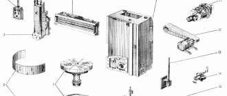
Location of machine components 1512
Location of machine components 1512
List of components of the machine 1512
- Table – 30
- Faceplate guard - 31
- Vertical support - 650
- Control pendant - 990
- Control panel suspension - 99
- Crossbar - 50
- Cross member movement mechanism - 57
- Bed - 10
- Mechanism for manual movement of vertical support - 420
- Vertical support feed box - 40
- Gearbox - 21
- Casing - 25
- Mechanism for transmitting movement to feed - 15
- Lubrication - 34
- Horizontal caliper (side) - 66
- Feed box horizontal caliper (side) - 46
A distinctive feature of the design of the machines is that most assembly units are made as independent products, which facilitates assembly not only during the manufacturing process, but also during repairs.
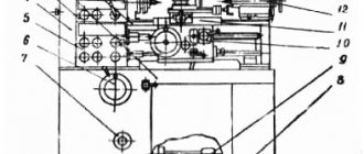
Location of controls for rotary lathe 1512
Location of controls for rotary lathe 1512
List of machine controls 1512
- Handle for fastening the cutting head of the side support
- Screw for fixing the cutting tool arbor in the turret socket
- Vertical support slider fixing screw
- Nuts for fastening the rotary slide of the vertical support
- Handle for connecting the machine to the electrical network
- Crossbar clamp handle
- Buttons for moving the crossbar “up”, “down”
- Square worm for rotating the vertical slide slide
- Vertical support fixing screw
- Flywheel for manual vertical movement of the vertical support slider
- Flywheel for manual horizontal movement of vertical caliper
- Control pendant
- Side caliper slider fixing screw
- Side support fixing screw
- Flywheel for manual horizontal movement of the side slider
- Flywheel for manual vertical movement of the side support
Machine passport 1525. Rotary lathe.
This operating manual “ Machine Passport 1525 ” contains information necessary both for the maintenance personnel of this machine and for the employee directly involved in working on this machine. This manual is an electronic version in PDF format of the original paper version. This documentation contains the Passport and Manual (instructions) for the operation of the 1525 rotary lathe.
CONTENT
TECHNICAL DESCRIPTION
- Purpose and scope
- Machine composition
- Design and operation of the machine and its components
- Lubrication system
USER MANUAL
- Safety instructions
- Installation procedure
- Setup, adjustment and operating modes
- Regulation
- Features of disassembly and assembly during repairs. Machine repair.
PASSPORT
- General information
- Basic technical data and characteristics
- Repair information
- Information about changes to the machine
- Delivery set
- Certificate of acceptance
- Certificate of conservation
download the passport of the rotary lathe 1525 in good quality from the link below.
Control panel for rotary lathe 1512
Control panel for rotary lathe 1512
List of controls on the machine control panel 1512
- "GENERAL STOP" button
- “NO LUBRICATION” warning light in the main drive
- Main drive STOP button
- Main drive START button
- Switch for turning on and off the vertical support brake
- Turret rotation and clamp button
- Switch for setting working feeds and installation movements of the vertical support
- Vertical support feed switch
- Switch for the direction of movement of the vertical support
- Signal light “VERTICAL CALIPER IN OPERATION”
- Light switch on/off
- Signal light “SIDE CALIPER IN OPERATION”
- Side support movement switch
- Side support feed switch
- Switch for setting working feeds and installation movements of the side support
- Switch for turning on and off the brake of side caliper movements
- Switch for faceplate revolutions per minute
- Switch for switching on and off step-constant cutting speed
- Faceplate START button
- Faceplate "STOP" button
- Switch for turning on and off the faceplate jog start
Production of rotary lathes
In the manufacture of rotary machines we use modern components. At the request of the customer, as well as for ease of operation and control, 1512 machines are available with a digital display device (DRO). Such models were designated 1512F1.
All guides are highly polished and, if necessary, scraped by hand. Mechanical components are equipped with modern bearings and ball screws, gears, shafts, couplings and other elements are mounted. We install the lubrication device and hydraulic equipment in agreement with the customer or according to the characteristics specified in the technical documentation.
Systems from domestic or imported manufacturers are installed on numerically controlled machines: Balt-System, SIEMENS, FANUC, HEIDENHAIN and others.
Kinematic diagram of machine 1512
Kinematic diagram of rotary lathe 1512
The kinematic diagrams of machines 1512 and 1516 are similar to each other and differ from each other only in the kinematics of the chain of the feed motion transmission mechanism and the number of teeth of the table gears.
Due to the different number of teeth on the table gears, machines 1512 and 1516 have different speed limits for the faceplate speeds with the same gearbox.
The kinematics of the chains of the feed motion transmission mechanism are different for the machines, but their gear ratios are selected in such a way that the total gear ratio of the kinematic chain from the faceplate to the feed box is the same for both machines. This allows you to use the same feed boxes and obtain the same feed amounts.
Kinematic diagram of a 1512F3 CNC vertical lathe.
Section: LIBRARY OF TECHNICAL LITERATURE Short path https://bibt.ru<<Previous page Book table of contents Next page>>
Kinematics of the machine 1512F3. The main movement (Fig. 55) is carried out from the electric motor M1 (N = 30 kW, n = 1460 min-1) through a V-belt drive with pulleys D = 230 mm and D = 266 mm and a gearbox providing 18 practical and 24 theoretical frequency values rotation of the faceplate as a result of switching electromagnetic couplings M1 - M7 and using a planetary mechanism. Shaft II has three rotation speeds obtained by switching couplings M1, M2, M3; shaft III - six rotation speed values (switched by couplings M4 and M5) and shaft IV - 12 rotation speed values (switched by couplings M6 and M7). To obtain the 12 lowest spindle speed values, turn off the M8 clutch and turn on the M9 and M10 clutches. In this case, wheel z = 63 on axis VII is braked and, through wheel z = 63 on shaft VI, stops wheel z = 87 of the planetary mechanism and, accordingly, its body with wheel z = 108. In this case, the gear ratio of the planetary mechanism is 1/4.
With clutches M9 and M10 turned off and M8 turned on, the planetary mechanism is one whole and its gear ratio is equal to one. When the M8, M9 and M10 clutches are turned on simultaneously, closing two different kinematic chains forming a “lock”, the faceplate is braked (the other gearbox clutches are turned off). Thanks to electromagnetic clutches, speeds are switched on the fly and thus a stepwise constant cutting speed is maintained when machining end surfaces.
Rice. 55. Kinematic diagram of a 1512F3 CNC vertical lathe
The kinematic chain equation for the minimum spindle speed will be as follows:
The threading sensor, necessary for cutting threads with cutters, receives rotation from the output shaft of the gearbox through gears z = 48-64, z = 24-24, z = 21-78. The rotation speeds of the sensor rotor and the faceplate are the same.
The feed movements of the 1512F3 machine come from DC electric motors M2 and M3 (M = 20.4 N*m; nnom = 1000 min-1) with thyristor control. The longitudinal feed rolling screw XII with a pitch Рх.в=10 mm receives movement from the electric motor M2 through a gear transmission z = 52-104, made with minimal lateral clearance. The transmission of rotation from shaft XI to screw XII is carried out by means of conical spring rings, eliminating any gap in the connection.
The maximum working longitudinal feed is determined from the expression
where 60 is the maximum engine speed at working feeds.
The vertical feed rolling screw XVII receives rotation from the M3 electric motor through a gearbox z= 43-40, z = 30-48, z = 32-44, z = 44-44. To regulate the lateral clearance in the gears, there are two parallel kinematic chains; in addition, the individual wheels are split
Minimum working vertical feed
where 0.6 is the minimum engine speed.
Linear inductosyns are used as feedback sensors.
Vertical movement of the cross member of the 1512F3 machine is carried out from a reversible electric motor M5 (N = 2 kW, n = 900 min-1) through worm gears z = 2-34. In the required position, the crossbar is securely fixed by a hydraulic clamping mechanism. The drive of the clamping-unclosing mechanism is carried out by the rod of the double-sided cylinder Ts1. The M11 gear coupling is used to install the cross member parallel to the working surface of the faceplate. Rotating the coupling half by one tooth gives the cross member movement by 0.005 mm.
Skip to navigation
Design of the main components of the rotary lathe 1512
Gearbox of machine 1512
The gearbox is used to ensure rotation of the faceplate, as well as starting, stopping and changing speeds. Rotation is transmitted to the input shaft of the gearbox from the main drive electric motor through a V-belt drive. The gearbox provides the faceplate with 18 speed levels.
The gearbox is controlled remotely from a pendant remote control.
The presence of electromagnetic clutches in the gearbox allows you to switch speeds on the go and thereby ensure the maintenance of a stepwise constant cutting speed when processing end surfaces.
The gearbox has six shafts mounted on rolling bearings in a housing with a parting plane along the shaft axes for ease of assembly.
At higher speeds, the start is carried out in stages in two, three or four stages. The number of acceleration stages increases with increasing speed of the faceplate.
Switching of clutches during stepwise acceleration is carried out automatically (for a detailed description, see Part 2 of the Operating Manual 'Electrical equipment of machine tools').
Changing the speed from 1st to 12th stage is carried out by turning on the corresponding combinations of electromagnetic clutches.
To enable the jog mode of operation of the faceplate, which is used when installing and aligning the part, it is necessary to place the switch on the pendant control panel in the “Jog start” position of the faceplate and press the “Start” button of the faceplate.
There are no special braking devices in the gearbox, and the faceplate is braked by simultaneous activation of three electromagnetic clutches.
Machine table
There are no fundamental design differences between the tables of machines 1516 and 1512. The machine parts are similar and differ from each other only in size.
The table consists of a body with circular guides, a faceplate with a spindle and a faceplate drive.
The table body is a cast iron with a developed system of ribs, giving it greater rigidity.
At the top of the table body there are annular projections that fit into the annular grooves of the faceplate, forming a labyrinth. This prevents lubricant from splashing and protects against chips, cast iron dust, emulsion and other contaminants getting inside the table.
The faceplate is driven from the gearbox through a pair of bevel gears with a circular tooth, then through a cylindrical helical pair: a gear and a ring gear rigidly connected to the faceplate.
Machine feed boxes
The design of the feed boxes of the lateral and vertical supports is the same.
The vertical support feed box is mounted on the right end of the cross member; side caliper feed box - directly to its body.
The feed box body is a box-shaped cast iron with sufficient rigidity. All feed box shafts are mounted on rolling bearings.
The feed boxes are driven from a vertical splined shaft, which receives rotation from the output shaft of the gearbox through the mechanism for transmitting movement to the feed (see Fig. 6).
The feed boxes provide the calipers with 18 working feeds and 18 speeds of installation movements. This is achieved by switching on the appropriate combinations of electromagnetic clutches of the feed boxes (for the switching diagram of electromagnetic clutches, see Part 2 of the Operating Manual 'Electrical equipment of machine tools*).
All gears of the feed boxes are in constant engagement.
A turret head with five slots and holes for attaching a tool is mounted on a cylindrical bushing. Changing the positions of the turret is carried out remotely from a pendant control panel. By pressing the “Turret Head” button, the electric motor for turning the turret head, mounted on the upper end of the slide, is turned on. Rotation from the electric motor is transmitted through gears to the drive shaft.
The main movement (rotation of the faceplate) is transmitted from the electric motor 1 through the V-belt transmission 2 - 3 to shaft I, then through the gearbox, shaft V, bevel gears 25 - 26 and wheels 27-28 is transmitted to the faceplate. The gearbox is equipped with eight electromagnetic clutches, the switching of which allows you to provide the faceplate with 18 rotation speeds ranging from 5 to 250 rpm.
The feeds of the calipers (revolving and side) are borrowed from the faceplate through two independent feed boxes with the same kinematics. Each box is equipped with eight electromagnetic clutches, switching which makes it possible to obtain 16 feed rates for both calipers.
Horizontal feed of turret support . From shaft VIII of the faceplate through gear 28 - 27, bevel gears 26 - 25, 24 - 23, gear 29 - 30 and bevel pairs of wheels 31 and 53, the movement is transmitted to shaft XII of the feed box (shown separately at the top left). From the feed box, the shaft XX of the caliper mechanism receives rotation, and then through gears 52 and a screw pair 65, the turret caliper receives horizontal feed.
Vertical feed of the turret support . From shaft VIII of the faceplate to shaft XXI of the feed box, rotation is carried out along the same chain; Then, through bevel gears 55 - 56, a cylindrical pair of wheels 57, a conical pair 58 and a screw pair 59, the turret caliper receives the feed movement.
Horizontal feed of side support . As before, the movement goes from shaft VIII of the faceplate to shaft XII of the feed box, then through the feed box to shaft XX and then through gears 39 - 41 and screw pair 42, the side caliper receives feed.
Vertical feed of side support . From the faceplate shaft to the feed box shaft XII, the movement proceeds along the same chain, then through the feed box the shaft XXI of the caliper mechanism receives rotation and through the bevel gears 35-36 and the screw pair 43 the side caliper receives feed.
Both supports receive accelerated movement
1512F3 Single-column rotary lathe with CNC. Passport, diagrams, characteristics, description
The developer and manufacturer of the two-column vertical turning lathe 1512F3 is the Krasnodar machine-tool plant Sedina, founded in 1911.
In 1915, the first lathe was produced. In 1922, the enterprise received its modern name - in honor of turner G. M. Sedin.
In 1935, the first rotary lathe, model 152, was produced, and by 1937, the priority profile of the plant was determined - machine tool building, and first of all, the production of rotary lathes.
Currently, the Sedin plant is PJSC Krasnodar Heavy Machine Tool Plant, PJSC Sedin.
Vertical turning machines produced by KSZS
Rotary lathes are used for processing heavy parts of large diameter and relatively short length. Almost all turning operations can be performed on these machines.
The horizontal arrangement of the plane of the round table (faceplate), on which the workpiece is fixed, greatly facilitates its installation and alignment. In addition, the spindle is relieved from bending forces, which ensures higher precision in machining parts. Vertical lathes are manufactured in two types; single-post and double-post. Machines with a faceplate with a diameter of up to 1600 mm are usually single-column, and machines with faceplates of larger diameter are usually double-column.
The P32-3M devices are most widely used as control devices for vertical turning lathes with CNC positioning systems, and the N55-2 devices for continuous systems.
CNC type N55-2, designed for automated control of multi-axis machines:
- the letter N means that the control is continuous, P - positional control F2
- the first digit 5 means the total number of controlled coordinates
- the second digit 5 means the number of simultaneously working coordinates
- the third digit 2 means that the automatic control system is closed in position, unlike a stepper electric drive, the sign of which is 1
The device is made according to the structure of a specialized computer with microprogram control, which makes it possible to provide control functions for both universal and special multi-axis machines that process complex planar and volumetric surfaces.
The machines can be equipped with other models of domestic and foreign control devices, for example from Alcatel (France), Bosch (Germany), etc.
When processing parts on a CNC lathe, the resulting accuracy of the machined surfaces mainly depends on the accuracy of the positioning of the working parts of the machine in a given position, and therefore the scattering field of absolute dimensions changes little with changes in the dimensions of the processed parts. As shown by the results of statistical processing of data from multiple control determinations of the dimensions of parts processed on CNC lathes under production conditions, the averaging of the magnitude of the size dispersion fields for machines 1512F2, 1516F2 and 1525F2 lies in the range of 0.12-0.15 mm when working without entering additional corrections and decreases to 0.08-0.10 mm when performing intermediate measurements and entering correction.
For high-precision machines with contour systems 1512F3, 1516F3 and 1525F3, these data are 0.10..0.12 mm and 0.04..0.06 mm, respectively. In practice, higher data can be obtained during processing, but such results cannot be consistently guaranteed.
Single-column vertical turning lathes models 1512F3 and 1516F3 are universal machines and are designed for processing a variety of products made of ferrous and non-ferrous metals in small-scale and mass production.
The machine can perform cylindrical and conical turning and boring, turning of planes, drilling, countersinking and reaming of holes, as well as semi-finishing and finishing turning of flat end surfaces.
The machine has two supports: a vertical one with a five-position turret with automatic rotation and fixation at each position, and a horizontal (side) one with a four-position tool holder.
The machines are designed for processing various workpieces made of ferrous and non-ferrous metals in single, small-scale and mass production.
The machines are equipped with a numerical program control device type N55-2, which provides automatic control of the upper support and the main movement drive gearbox according to a given program.
The machines can be used to grind and boring surfaces with straight and curved generatrices, drilling, countersinking and reaming of central holes, cutting annular grooves, as well as processing end surfaces.
The machines are made with one upper support, a five-position turret and automated rotation and fixation at each position.
Significant drive power of the main movement, high rigidity of the base parts, sufficient strength of all elements of the kinematic chains, wide ranges of control of the faceplate rotation speeds and caliper feed rates in combination with automatic control allow the machine to carry out high-performance processing of workpieces of complex configurations.
The technological capabilities of the machine are significantly expanded with the help of a self-centering faceplate supplied upon special order, devices (for thread cutting, processing of conical surfaces, turning shaped surfaces of bodies of revolution along a copier, processing parts on stops) and a device for processing with cooling.
The following operations can be performed on the machines:
- turning cylindrical and conical surfaces;
- boring of cylindrical and conical surfaces;
- turning flat end surfaces using vertical and lateral supports.
In addition, a vertical support can be used to grind flat end surfaces while maintaining a stepwise constant cutting speed in finishing and semi-finishing modes; drilling, countersinking and reaming; Grooving and parting.
When using special devices and devices that are supplied with the machines upon special order for an additional fee, the machines can produce:
- processing of parts according to specified dimensions (on stops);
- cutting threads, turning and boring conical surfaces;
- processing of shaped surfaces of bodies of rotation using a copier (electrocopier);
- processing of parts with cooling.
In the usual version, the machines are supplied with a vertical turret support, which has a mechanical rotation and clamping of the turret head, and a side support.
In addition, upon special order, for an additional fee, a machine with a self-centering faceplate with manual clamping of the product can be supplied.
All accessories can be mounted on the machine at the same time, with the exception of cooling, which cannot be installed simultaneously with the self-centering faceplate.
Due to the fact that the installation of fixtures requires significant changes and modifications to the machine, orders for the manufacture of fixtures for previously supplied machines cannot be fulfilled. Accessories are supplied only with the machine.
Design organization - Krasnodar Machine Tool Plant named after. G. M. Sedina.
Dimensions of the working space of the 1512F3 CNC machine
Landing and connecting bases for rotary lathe 1512F3
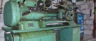
Photo of rotary lathe 1512F3
Kinematic diagram of rotary lathe 1512F3
Kinematic diagram of the rotary lathe 1512F3. View enlarged
The main movement - the rotation of the faceplate - is carried out from the electric motor M1 (Fig. 106) through a V-belt drive with pulleys F233 and F266, a gearbox, shaft V, bevel gears 48/36 and gears 25/125. The kinematic balance equation has the form:
1460 x (230/266)ηiv(48/36) x (25/125) = n,
where iv is the gearbox gear ratio.
From shaft V of the gearbox through bevel gears 36/48, shaft IX, gears 36/54, rotation is transmitted to shaft X, bevel gears 17/17, shaft XI, bevel gears 23/23, rotation is transmitted to shaft XII of the feedbox , by switching the electromagnetic clutches of which the required flow is established. The equation for the kinematic balance of the feed chain has the form:
1ob.pl. x (125/25) x (36/48) x (36/48) x (36/54) x (17/17) x (23/23)isic = S mm,
where is is the gear ratio of the feed box;
ic is the gear ratio of the chain from the feedbox to the corresponding caliper.
The horizontal feed of the turret support is carried out from the output shaft XX of the feed box through a 22/22 gear and a lead screw with a pitch of 8 mm, and for the side support through gears (21/37), (37/37), (37/21) and lead screw with 8 mm pitch. Vertical feed is carried out from the output shaft of the XXI feed box for the turret support through gears (22/22)(22/22)(22/22) and a lead screw with a pitch of 8 mm, and for the side support through gears (20/23) (20/20) and a lead screw with a pitch of 8 mm.
Accelerated movements of the caliper are obtained from a separate electric motor M2. The traverse is raised and lowered by rotating two lead screws with a pitch of 8 mm. The rotation of the turret caliper is carried out by the M3 electric motor through gears (18/34)(34/45) and a 1/25 worm gear. The turret caliper is moved manually by rotating handwheels 3 and 4, and the side caliper by rotating handwheels 1 and 2.
To increase the productivity and accuracy of processing, devices are used for installing workpieces on the machine faceplate without alignment (basic faceplates), devices for processing conical and shaped surfaces, as well as for securing and accurately installing cutting tools.
The 1512FZ machine is equipped with a CNC device of the N55-22 type, which automatically controls the upper (vertical) turret support and the main movement drive according to a given program entered from an eight-track punched paper tape. The control of the machine's executive bodies can also be carried out in the preliminary set mode (manual data entry) using switches and buttons located on the CNC control panel, and in the adjustment mode (from the pendant console).
The CNC ensures operation of the machine in the following modes:
- Full program
- Main program
- Accelerated program
- Frame search
- Exit to a given point
- Frame
- Setup
- Original
CNC parameters:
- Information coding system - ISO - 7 bits
- Contour control in two coordinates, linear and circular interpolation
- Largest interpolation radius 4999.99 mm
- Interpolation accuracy 0.01 mm
- The discreteness of counting movements along both coordinates is 0.01 mm
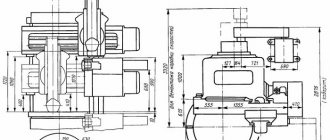
Installation drawing of machine 1512F3
Installation drawing of rotary lathe 1512F3. View enlarged
1512F3 Single-column rotary lathe with CNC. Video.
Parameter name 1512F3 1516F3
| Main settings | ||
| Maximum diameter of the product, mm | 1250 | 1600 |
| Maximum height of the workpiece, mm | 1000 | 1000 |
| Faceplate diameter, mm | 1120 | 1400 |
| Diameter of the centering hole in the faceplate, mm | 150N7 | 260N7 |
| Maximum weight of the installed product, kg | 4000 | 6300 |
| at 5-80 faceplate revolutions per minute | 3200 | 6300 |
| at 100 faceplate revolutions per minute | 3000 | |
| at 125 faceplate revolutions per minute | 2700 | |
| at 160 faceplate revolutions per minute | 1900 | |
| at 200 faceplate revolutions per minute | 1300 | 2400 |
| at 250 faceplate revolutions per minute | 1000 | |
| Vertical support | ||
| Maximum horizontal movement, mm | 775 | 950 |
| Maximum vertical movement, mm | 700 | 700 |
| Maximum angle of rotation of the caliper slider, degrees | 45 | 45 |
| Caliper slider rotation dial division price, min | 1 | 1 |
| Caliper slider rotation scale division value, deg | 1 | 1 |
| Diameter of caliper turret holes, mm | 70A | 70A |
| The largest cross-sectional dimensions of the cutter holder (width x height), mm | 25 x 40 | 25 x 40 |
| Cross member | ||
| Maximum displacement, mm | 660 | 660 |
| Travel speed, mm/min | 400 | 400 |
| Machine mechanics | ||
| Number of faceplate speeds | 18 | 18 |
| Faceplate revolutions per minute | 5..250 | 5..250 |
| Number of caliper feeds | 18 | 18 |
| Caliper working feed speed, mm/rev | 0,01..40 | 0,01..40 |
| Maximum permissible cutting force with a caliper, kgf | 4500 | 4500 |
| Speed of installation movements of the vertical support, mm/min | 3000 | 3000 |
| Maximum permissible torque on the faceplate, N*m | 11000 | 11000 |
| Drive and electrical equipment of the machine | ||
| Type of supply current | AC three-phase | AC three-phase |
| Main motion drive electric motor, kW | 30 | 30 |
| Electric motor for caliper installation movements, kW | 3 | 3 |
| Electric motor for moving the crossbar, kW | 2 | 2 |
| Lubrication motor, kW | 1,5 | 1,5 |
| Electric motor for turning and clamping the turret head, kW | 0,8 | 0,8 |
| Total power of all electric motors on the machine, kW | 38 | 38 |
| Dimensions and weight of the machine | ||
| Machine dimensions (length x width x height), mm | 2920 x 3610 x 5615 | 3170 x 3810 x 5615 |
| Machine weight, kg | 15500 | 19000 |
Useful links on the topic
Catalog directory of rotary lathes
Passports and manuals of rotary lathes
Directory of woodworking machines
Buy a catalog, directory, database: Price list of information publications
stanki-katalog.ru
Characteristics of the electrical equipment of the machine 1512
Electrical circuit of the power supply of the machine 1512
Electrical circuit of the power supply of the rotary lathe 1512
The electrical equipment of machine tools consists of electric motors, electrical controls, limit switches to limit the movement of moving parts of the machine and control equipment.
The machines are equipped with five three-phase asynchronous electric motors with a squirrel-cage rotor:
- main drive motor 1M1;
- oil pump drive motor 1M2;
- cross member movement motor 1M3;
- motor for installation movements of the upper support, installation movements of the side support 4M1 and three single-phase asynchronous capacitor electric motors with a squirrel-cage rotor to drive the lubricator of the lubrication system;
- cross member motor 1M4;
- upper support motor 2M2 and 2M3
The following voltage values are accepted on the machine
- 380V three-phase alternating current, frequency 50 Hz - power supply of power circuits;
- 110V single-phase alternating current - power supply to coils of magnetic starters and single-phase electric motors;
- 36V single-phase alternating current - power supply for the circuit for selecting the direction of travel of the stepper finder;
- 24V - DC power supply for local lighting lamps;
- 24V - DC power supply for control circuits and electromagnetic couplings;
- 90V - DC power supply to the stepper finder coils.
All electrical equipment for controlling the machine is located in the niche of the machine. The machine is controlled from a pendant control panel.
The electrical equipment of the machine performs the following functions:
- Faceplate control:
- start-up in operating mode;
- start in jog mode;
- step change in speed with a rotating faceplate;
- maintaining a stepwise constant cutting speed when turning end surfaces with the upper support (changing the speed of rotation of the faceplate using a cam rack and a limit switch);
- faceplate stop.
Caliper control:
- working feeds (feed selection and switching on);
- installation movements (selection of movement speed and switching on).
Moving the cross member.
Description of electrical equipment operation
The electrical circuit provides for the following operations
- starting and stopping the main drive electric motor and the lubrication system electric motor;
- raising and lowering the cross member.
Main drive motor control
The main drive electric motor is controlled from a pendant control panel using buttons 1Кн2 - “Start” and IKHI - “Stop”.
When you press the 1Kn2 - “Start” button, the main drive starter 1K1 is turned on. At the same time, the 1P1 relay for limiting the idle speed of the main drive electric motor is turned on, which operates with a time delay. If the faceplate is not turned on during this time, the open contact of this relay (circuit 4) will turn off the main drive starter.
The main drive electric motor is turned off by pressing the IKHI - “Stop” button.
When the faceplate is turned on, the IKHI button is blocked by the closing contact of the step finder SHIT. The main drive motor can only be turned off after the faceplate has been turned off and the step finder is in the zero position.
- everything you need to know about the connection diagram
What is a connection diagram?
An electrical diagram is a simple visual representation of the physical connections and physical layout of an electrical system or circuit. It shows how electrical wires are connected to each other and also shows where devices and components can be connected to the system.
When and how to use a wiring diagram
Use wiring diagrams to help design or manufacture a circuit or electronic device. They are also useful for making repairs.
DIY enthusiasts use electrical wiring diagrams, but they are also common in home construction and car repair.
For example, a home builder will want to confirm the physical location of electrical outlets and light fixtures using a wiring diagram to avoid costly mistakes and building code violations.
How to draw a circuit diagram
SmartDraw comes with ready-made electrical connection templates. Customize hundreds of electrical symbols and quickly add them to your electrical circuit. Dedicated control knobs around each symbol allow you to quickly resize or rotate them as needed.
To draw a wire, simply click on the Draw Lines option on the left side of the drawing area. If you right-click on a line, you can change the color or thickness of the line and add or remove arrows as needed. Drag the symbol onto the line and it will insert and snap into place. Once connected, it will stay connected even if you move the wire.
If you need additional symbols, click the arrow next to a visible library to open a drop-down menu and select More. You will be able to search for additional symbols and open any relevant libraries.
Click Set Line Transitions in SmartPanel to show or hide line transitions at intersection points. You can also change the size and shape of your hop lines. Select Show Dimensions to show the length of your wires or the size of your component.
Click here to read SmartDraw's complete tutorial on how to draw circuit diagrams and other electrical diagrams.
How does a wiring diagram differ from a diagram?
A diagram shows the layout and function of an electrical circuit, but does not show the physical layout of wires. A wiring diagram shows how wires are connected, where they should be in an actual device, as well as the physical connections between all of the components.
How does an electrical diagram differ from a graphic diagram?
Unlike a pictorial diagram, a wiring diagram uses abstract or simplified shapes and lines to show components. A pictorial diagram is often a photograph with labels or highly-detailed drawings of the physical components.
Standard Wiring Diagram Symbols
If a line touching another line has a black dot, it means the lines are connected. When unconnected lines are shown intersecting, you will see a line transition.
Most of the symbols used in an electrical diagram look like abstract versions of the real objects they represent. For example, a switch would be a break in a line with a line at an angle to the wire, like a light switch that can be turned on and off. The resistor will be represented by a series of plugs symbolizing current limitation. The antenna is a straight line with three small lines branching off at the end, much like a real antenna.
- conductive wire
- Fuse, cut off when current exceeds a certain value
- Capacitor used to store electrical charge
- Toggle switch stops current when opened
- Push-button switch, instantly passes current when the button is pressed, interrupts the current when released
- A battery stores electrical charge and generates constant voltage
- Resistor, limits current flow
- Ground wire used for protection
- Circuit breaker used to protect a circuit from overcurrent
- Inductor, a coil that generates a magnetic field
- Antenna transmits and receives radio waves
- Surge protector used to protect a circuit from surge voltage
- Lamp generates light when current passes through
- Diode, allows current to flow in one direction, indicated by an arrow or triangle on the wire
- Microphone converts sound into an electrical signal
- Electric motor
- Transformer, changes alternating voltage from high to low or vice versa
- Headphones
- Thermostat
- Electric outlet
- Junction box
Examples of electrical connections
The best way to understand electrical circuits is to look at some example electrical diagrams.
Click on any of these electrical diagrams included in SmartDraw and edit them:
Browse the entire SmartDraw collection of diagram examples and templates
,
Technical characteristics of the rotary lathe 1512
| Parameter name | 1512 | 1516 |
| Main settings | ||
| The largest diameter of the product processed by vertical and lateral supports, mm | 1250 | 1600 |
| Maximum height of the workpiece, mm | 1000 | 1000 |
| Faceplate diameter, mm | 1120 | 1400 |
| Maximum weight of the installed product, kg | ||
| at 5-80 faceplate revolutions per minute | 3200 | 6300 |
| at 100 faceplate revolutions per minute | 3000 | |
| at 125 faceplate revolutions per minute | 2700 | |
| at 160 faceplate revolutions per minute | 1900 | |
| at 200 faceplate revolutions per minute | 1300 | 2400 |
| at 250 faceplate revolutions per minute | 1000 | |
| Vertical support | ||
| Maximum horizontal movement, mm | 775 | 950 |
| Maximum vertical movement, mm | 700 | 700 |
| Price for dividing the horizontal and vertical movement dial, mm | 0,05 | 0,05 |
| Horizontal and vertical movement per one revolution of the dial, mm | 2,5 | 2,5 |
| Maximum angle of rotation of the caliper slider, degrees | 45 | 45 |
| Caliper slider rotation dial division price, min | 1 | 1 |
| Caliper slider rotation scale division value, deg | 1 | 1 |
| Diameter of caliper turret holes, mm | 70A | 70A |
| The largest cross-sectional dimensions of the cutter holder (width x height), mm | 25 x 40 | 25 x 40 |
| Horizontal caliper (side) | ||
| Maximum horizontal movement, mm | 630 | 630 |
| Maximum vertical movement, mm | 1000 | 1000 |
| Price for dividing the horizontal and vertical movement dial, mm | 0,05 | 0,05 |
| Horizontal and vertical movements per one revolution of the dial, mm | 2,5 | 2,5 |
| Cross member | ||
| Maximum displacement, mm | 660 | 660 |
| Travel speed, mm/min | 400 | 400 |
| Switching stops | Available | Available |
| Blocking movement during cutting | Available | Available |
| Machine mechanics | ||
| Number of faceplate speeds | 18 | 18 |
| Faceplate revolutions per minute | 5 — 250 | 5 — 250 |
| Number of caliper feeds | 18 | 18 |
| Vertical and horizontal feeds of calipers, mm/rev | 0,03 — 12,5 | 0,03 — 12,5 |
| Maximum permissible cutting force with two supports, kgf | 4500 | 4500 |
| Speed of installation movements of calipers, mm/min | 5 — 1800 | 5 — 1800 |
| Drive and electrical equipment of the machine | ||
| Type of supply current | AC three-phase | AC three-phase |
| Main drive electric motor: | ||
| power, kWt | 30 | 30 |
| Rotation speed, rpm | 1460 | 1460 |
| Electric motor for installation movements with caliper: | ||
| power, kWt | 3 | 3 |
| Rotation speed, rpm | 1365 | 1365 |
| Electric motor for moving the crossbar: | ||
| power, kWt | 2 | 2 |
| Rotation speed, rpm | 900 | 900 |
| Lubrication motor: | ||
| power, kWt | 1,5 | 1,5 |
| Rotation speed, rpm | 1450 | 1450 |
| Turret head rotation and clamping motor: | ||
| power, kWt | 0,8 | 0,8 |
| Rotation speed, rpm | 1450 | 1450 |
| Dimensions and weight of the machine | ||
| Machine dimensions (length x width x height), mm | 2750 x 2975 x 4100 | 3170 x 3030 x 4100 |
| Machine weight, kg | 16 500 | 20 000 |
Specifications
Full technical specifications are described in the instruction manual.
- The installed workpiece can have a maximum of the following parameters in terms of weight, height and diameter: 4000 kilograms, 1000 and 1250 millimeters, respectively.
- 11200 is the diameter of the platform itself.
- 5-250 rpm – angular speed for the faceplate.
- The tool feed rate is 0.03-12.5 revolutions per minute. In total, this and the previous indicators have up to 18 steps.
- 5-1800 – speed according to installation movements.
- The power of the main movement is 30 kW.
- 16.5 is the total mass for installation.