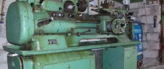
Information about the manufacturer of the OT-5 screw-cutting lathe
The manufacturers of the OT-5 screw-cutting lathe were the Odessa Machine Tool Plant and the Kirovakan Precision Machine Tools Plant in Kirovokan - Vanadzor .
Currently, production of the machines has been discontinued.
Machine tools produced by the Odessa Machine Tool Plant
- 1P611
– universal screw-cutting lathe Ø 250 - 16B05A
- universal screw-cutting lathe Ø 250 - 16B05P
- universal screw-cutting lathe Ø 250, Kirovakan - 16М05А
– universal screw-cutting lathe Ø 250 - 1601
— table lathe Ø 125 - 1604
— universal screw-cutting lathe Ø 200 - OT-4
– screw-cutting lathe Ø 250 - OT-5
– screw-cutting lathe Ø 250
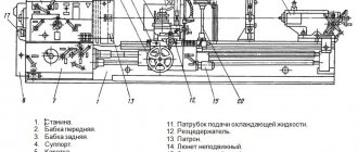
OT-5 Arrangement of components of a screw-cutting lathe
Location of the components of the OT-5 lathe
List of main components of the OT-5 lathe
- Bed - 16B05P.111.000
- Cabinet - OT-5.121.000
- Front headstock - OT-5.221.000
- Guitar – 16B05P.311.000
- Feed box - 16B05P.321.000
- CVT - 16B05P.211.000
- Switch - OT-5.821.000
- Frame - OT-5.131.000
- Lubrication unit - 16B04P.411.000
- Apron - 16B04P.331.000
- Caliper - 16B05P.341.000
- Rear headstock - OT-5.231.000
- Cooling - OT-5.511.000
- Fencing – OT-5.611.000
- Electrical equipment - OT-5.811.000
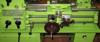
OT-5 Location of controls for a screw-cutting lathe
Location of controls for the OT-5 lathe
List of controls for the OT-5 screw-cutting lathe
- 1. Speed selector knob
- 2. Thread pitch increasing link handle
- 3. Feed drive reverse handle
- 6. Feed and thread switching handle
- 7. Handle for switching feeds and threads
- 8. Handle for turning on the lead screw or lead shaft
- 9. Handle for switching feeds and threads
- 10. Feed and thread switching handle
- 11. Variator speed shift knob
- 13. Handwheel for changing spindle speeds
- 14. Spindle rotation control handle
- 21. Cooling switch
- 23. Introductory machine
- 25. Handle for turning on the apron safety device
- 26. Handwheel for adjusting the amount of traction force
- 28. Handle for turning on the uterine nut
- 29. Button for switching longitudinal and transverse feed of the caliper
- 31. Handwheel for moving the tailstock quill
- 32. Tailstock clamp handle
- 33. Handle for moving the upper carriage
- 34. Tailstock quill clamp handle
- 36. Light switch
- 37. Tool holder clamp handle
- 38. Manual lateral movement handle
- 39. Handwheel for manual longitudinal movement
- 40. Button for turning on the handwheel and longitudinal feed dial
Design features
A special feature is the presence of a variator. It allows you to change the spindle speed. The rotation of the main engine through a V-belt system and a gear coupling transmits the rotation of the spindle to the variator input shaft. The change in speed occurs due to a change in the distance between the conical disks.
By reducing the gap, the discs push the V-belt to the edge and the diameter of the pulley increases. The gear ratio increases - the spindle speed increases. The same design is used on the variator output shaft.
Placing the variator on the frame without connection with the stand and installing the apron on an independent suspension reduces the vibration level. The use of precision bearings and the rigidity of the machine structure ensure precise processing of parts.
The feed box allows you to cut threads in the range of:
- metric (in mm) from 0.2 to 28;
- modular (in mod) from 0.1 to 14;
- inch (threads per inch) from 5 to 96.
Changing the speed of longitudinal and transverse feeds without changing the gears in the guitar.
Dimensions and weight
Overall size: 0.725m x 1.36m x 1.51m.
Weight in kg – 765.
Location of components
- The cabinet contains inside a lubrication mechanism, a main drive, a variator, and a box with electrical equipment. The cabinet is mounted on a frame with a level adjustment mechanism.
- The bed is fixed in the upper part of the cabinet. It houses the headstock, tailstock and apron.
- The headstock includes the spindle assembly, guitar and feed box.
- The apron is equipped with a support with a tool holder, a mechanism for longitudinal and transverse feeds, and a protective shield.
- The tailstock moves along the frame guides and is secured with bolts.
Control structure
The controls are located on the front of the machine and are grouped where the mechanisms they control are located.
The variator is controlled:
- The variator speed shift knob (switches the spindle speed ranges).
- The flywheel changes the spindle speed (the spindle speed is smoothly controlled by moving the sliding disk of the planetary gear).
- Spindle rotation control handle (switches the direction of spindle rotation).
On the front side of the headstock casing there are switches for controlling speed selection, a link for increasing the thread pitch, reversing the feed drive, switching feeds, turning on the lead screw and roller, and switching feeds.
These elements control the gearbox and the engagement of gears on the lead shaft or lead screw. Control occurs by selecting the required combinations of gear engagement and gear couplings of the gearbox.
Kinematic diagram
The electrical circuit consists of two asynchronous motors powered by a 380 V industrial AC network. It is possible to power a step-down transformer from a 220 V network.
Provides 12 V to power the lighting lamp and 110 V to power the circuit controls. These switch buttons, starters and overcurrent protection elements (thermal relays). Electrical equipment is the main weak point of the machine. Requires constant monitoring.
Electrical diagram
Variable speed drive
The variator consists of a two-stage gearbox and the variator itself. The main motor rotates the drive shaft through a gear coupling. There are two conical disks on the shaft. One is rigidly fixed, and the other is spring-loaded and can move along the axis.
These two discs form the drive pulley of the variator. The drive pulley uses a V-belt to rotate another pair of identical disks, forming the driven pulley. They are located on the driven shaft. It transmits rotation to the gears of the range switching box.
Headstock
The front (spindle headstock) is rigidly fixed to a massive frame. The spindle head housing contains:
- spindle - rotates in precision rolling bearings;
- overkill - a set of gears that allows you to expand the range of thread pitch by changing the gear ratio;
- lead screw drive with bit (controls change in feed direction);
- control mechanism;
- mechanism for supplying lubrication to bearings and gears.
Gearbox
The feed box and guitar change the gear ratio to cut threads with different pitches and obtain longitudinal and transverse feeds.
Caliper
The cross-type machine support consists of:
- lower slide – moves longitudinally along the frame guides;
- cross slide – moves in the transverse direction;
- rotary slide – fixed on the cross slide and set to the required angle according to the scale marked on the cross slide. Used for making cones;
- tool holder – rotatable to 4 positions with locking.
Apron
Designed to provide longitudinal and transverse feed of the caliper. Equipped with a mechanism for blocking the simultaneous activation of the lead screw and the lead shaft.
OT-5 Kinematic diagram of a screw-cutting lathe
Kinematic diagram of the screw-cutting lathe OT-5
The kinematic diagram of the machine allows the following operations:
- the main movement is spindle rotation
- feed movement - cutter movement
- rotation of the lubrication pump
Technical characteristics and operating principle
Lathe Features:
- normal accuracy of turning parts;
- the presence of additional supports allows you to sharpen long parts;
- the largest size of the workpiece is 100 cm, above the support – 60 cm;
- maximum workpiece weight – 5000 kg;
- the equipment operates using 4 electric motors of different power;
- cooling and lubrication are carried out using two pumps;
- the caliper can move both along and across in accelerated mode;
- Changing gears allows you to precisely adjust the size of thread pitches.
The main working moment is cutting the part while it is rotating in the chuck or centers. The cutting tool can be moved using the auxiliary feed motion.
Cross feed regulates the processing depth. The cutter configuration determines the shape of the part.
OT-5 Variator for screw-cutting lathe
Variator of screw-cutting lathe from-5
CVT (continuously variable gearbox)
The variator consists of the variator itself and a two-stage gearbox (range shift box).
The first (drive) shaft 2 of the variator is driven into rotation by a flanged electric motor through a gear coupling half. The second half of the coupling is made integral with shaft 2, on which a stationary (in the axial direction) disk 4 and a spring-loaded sliding disk 3 are installed, forming the variator drive pulley. From this pulley, rotation is transmitted through a wide V-belt to shaft 7 through the driven variator pulley, consisting of a fixed disk 5 and a controlled sliding disk 6.
In addition to the driven pulley, gears 8 and 9 are located on shaft 7. Gear 9 is equipped with an outer and inner ring gear and a half-coupling. Gear 8, moving along the splines along shaft 7, switches the speed ranges of the variator output shaft. The drive pulley of the V-belt drive, connecting the variator to the headstock, is mounted on this shaft. To tension the transmission, the housing 11 of the variator gearbox can be rotated on the glass 10, mounted on the housing 1 of the variator. The housing 11 is rotated using the coupling nut 21, after which the housing is secured with screws to the glass 10.
The control mechanism for the variator and gearbox is located on top of the variator body. Handwheel 12 controls the movement of sliding disk 6, handle 16 serves to switch gears in the gearbox. A planetary gear 20—19—18—17 connects the handwheel 12 with a disk 13, on which a ring 14 with a dial 15 is installed. There are two spindle speed scales on the dial, one for directly turning on the spindle, the second for turning on the spindle through overdrive.
To read the scales, two pairs of indicator strokes are used, printed on a transparent shield located above the dial. When switching variator speeds, the shield moves together with handle 16. For counting, use the pair of index strokes that is currently in the upper position.
DIP-300 universal screw-cutting lathe. Purpose and scope
The universal screw-cutting lathe model DIP-300 (according to the classification ENIMS 1d63) is the first Soviet machine with a gearbox and a processing diameter over the bed of 615 mm, like all other DIPs (, , ,), developed and produced at the Moscow machine-tool plant Krasny Proletary from 1930 to 1950s.
The DIP-300 lathe is designed to perform a wide variety of work on centers, collet or jaw chucks for ferrous and non-ferrous metals, including turning cones, as well as for cutting metric, modular, and inch threads.
The DIP-300 (1d63a) lathe is capable of processing relatively large workpieces with a diameter of up to 615 mm and a length of 1500 or 3000 mm.
The front end of the spindle is threaded M120 x 6, the internal Morse taper is 5, the hole in the spindle is 70 mm, the diameter of the processed rod is 68 mm.
The spindle of the DIP-300 (1d63a) machine is mounted on double-row roller bearings at the front and in a tapered roller bearing at the rear. The axial load on the spindle is carried by a thrust ball bearing.
The spindle receives 18 stages of forward and reverse rotation frequencies from a six-shaft gearbox in the headstock of the machine. Setting the desired speed is carried out by three handles on the front wall of the headstock.
Starting, stopping and activation of accelerated reverse motion is carried out by a friction plate clutch. The clutch is controlled by handles on the frame at the headstock and on the apron.
The motion is supplied to the input shaft of the gearbox through a belt drive from an asynchronous electric motor with a power of 10 kW.
The feed box receives movement from the gearbox through the guitar - replaceable gears with an angle. The headstock includes mechanisms that make it possible to change the direction of movement of the caliper and speed up this movement (increase the thread pitch) by 4 and 16 times.
To produce high-precision threads, the lead screw can be connected through the guitar's replacement gears in addition to the feed mechanism.
The caliper receives feeds along the running roller: longitudinal from 0.10 to 1.6 mm and transverse from 0.04 to 0.59 mm per spindle revolution.
The support apron of the DIP-300 (1d63a) lathe is equipped with a falling worm mechanism, which makes it possible to automatically turn on the feed from the lead screw when cutting threads in both directions and at the same time protects the machine from damage in case of overload. Disconnection is carried out with an accuracy of 0.02 mm from the stop on the frame.
History of the screw-cutting lathe DIP-300
In 1930, a decision was made to develop a new standard lathe, abbreviated as TS. Somewhat later it was renamed “ Let’s Catch Up and Overtake
, according to the main slogan of the first five-year plan, where 200 is the height of the centers above the frame.
from the German company VDF
was chosen as a prototype . In April 1932, preparations began for the release of the first batch of DIP-200 machines.
On April 25, 1932, the first Soviet universal screw-cutting lathe with a gearbox, DIP-200, was assembled and tested. By the end of 1932, 25 DIPs were produced.
IN 1934
year, the Moscow machine tool plant “Krasny Proletary” mastered the production of heavy universal screw-cutting lathes, , .
IN 1944
year, the production of these machines was transferred to the Tbilisi Machine Tool Plant, founded in 1944. Kirov and Yeisk Machine Tool Plant.
IN 1956
The Ryazan Machine Tool Plant produced the first industrial batch of machines of the DIP-300 series - model - RMC 1400, 2800.
IN 1968
year, the next generation of the series was launched into production - the model, .
WITH 1973
beginning of serial production of lathes: , , , , .
Tbilisi Machine Tool Plant named after. Kirov produced machines: , 1M63D, 1M63DF101.
IN 1992
year, the serial production of the machine began - the latest model of the DIP-300 series.
OT-5 Spindle head of a screw-cutting lathe
Spindle head of screw-cutting lathe OT-5
The headstock housing contains:
- spindle
- overkill
- drive of threads and feeds with bit
- control mechanism
The headstock take-up pulley 8 is mounted on a bushing 11, coaxial with the spindle 4. To the left of the pulley there is a direct spindle coupling 10, and to the right there are gear wheels 2, 6, 7, 11.
The machine spindle rotates in precision rolling bearings.
A double-row roller bearing and two angular contact ball bearings are installed in the front spindle support, and a radial ball bearing is installed in the rear support.
The rear support of the spindle and the left support of the sleeve 11 of the pulley 8 are located in the cup 9. When replacing drive belts, this cup must be removed.
The gear ratio of the headstock is 1/8. The control of the headstock 6, 7 and the direct clutch 10 is carried out with one handle. Next to the selection gear 11 on the spindle 4 there is a gear 3 for driving threads and feeds. The gear wheel 1, located on the first shaft 12 of the drive of threads and feeds, can be connected either to the gear wheel 11, or to the gear wheel 3 sitting on the spindle. This makes it possible to increase the thread pitch when enumeration is turned on.
Changing the direction of feed or cut thread is carried out by a snaffle consisting of a double gear wheel 13, a sliding gear wheel 15 and a parasitic wheel 16. The wheel 15 is seated on the splines of the output shaft 14, onto the end of which one of the replacement wheels of the guitar is put on.
The control handles for the headstock mechanisms are located on the front wall of the headstock. A cast casing is attached to the headstock body 5 in front, in which control buttons for the main electric motor are installed.
Lubrication of the headstock mechanisms is centralized, from a lubrication unit.
Adjusting spindle bearings in the OT5 machine
Layout of bearings for a screw-cutting lathe from-5
Spindle bearings for screw-cutting lathe from-5
The spindle of the machine from-5 is mounted on 4 bearings:
- 22. Front bearing No. 4-3182111 GOST 7634-56 double-row radial roller, accuracy class 4
- 24.25. Bearing No. 4-46111 GOST 831-62 angular contact ball, accuracy class 4
- 32. Rear bearing No. 4-308 GOST 8338-57 radial ball, accuracy class 4
Adjusting spindle bearings
The front end of the spindle of a screw-cutting lathe from-5
To adjust the radial clearance of a double-row roller bearing of the front spindle support, you must:
- Press in the stop screw 7 (Fig. 26).
- Loosen flange 5 from the fastening and move it to the right.
- Move safety ring 6 to the right
- Remove two half rings 4.
- Grind half rings 4 to the size determined by the formula:
A = B - δ mm,
Where
B—thickness of the removed half-rings 4 before grinding, mm;
δ is the magnitude of the required displacement of the inner ring of the bearing δ relative to the spindle journal 8.
The displacement value δ is determined by the formula:
δ = 15(Δо - Δ + 0.01) mm,,
Where
Δо - initial radial clearance (before adjustment), mm; Δ is the required radial clearance of the bearing, mm.
Screw-cutting lathes mod. from-5 are supplied with radial clearance Δ = 0.003 to 0.005 mm.
- Install half rings 4.
- Return safety ring 6 and locking screw 7 to their previous position.
- Using nut 2, move the inner ring of bearing 3 in the axial direction until it stops relative to the spindle journal 8.
- After selecting the gap, lock nut 2 with screws 1
- Install and secure flange 5.
- Check the actual radial clearance obtained. If necessary, repeat the adjustment. All dimensions should be measured to the nearest 0.001 mm.
Technical characteristics of bearing No. 3182111
Bearing 3182111 is a double row radial roller bearing, with short cylindrical rollers, with a flangeless outer ring (as a result of which the set of rolling elements on the cage is able to move and create a “floating” support), with a tapered seat bore (1:12), groove and holes for adding lubricant.
The main place of operation of such bearings is machines for various applications, units where high radial loads and speeds are applied. This standard size, like most roller bearings in this series, is currently produced only with high precision. The bearing has always been produced at the Moscow GPZ-1 plant, but now, unfortunately, it has been discontinued and you can buy it directly only from companies that sell bearings from storage, surplus stock, used, and cleaned. You can find products of 2, 4, 5 and 6 accuracy classes. The designation to the right of the number is most often L (brass separator, old). The price of bearings greatly depends on their accuracy and safety class, from 300 to 2300 rubles.
Imported bearings of this size are designated NN3011K (the presence of the letter K in the number is mandatory, as it indicates a tapered fit). Products of different price categories are supplied to Russia: the most expensive and reliable are FAG, SKF, KOYO, IBC, the cheaper ones are NACHI and NSK. An even cheaper option is products from Eastern European manufacturers - ZKL and FLT, which are most often sold in illiquid quality, sometimes even used. The estimated price of the highest quality and most expensive bearings of this type is about 275 euros.
Dimensions and characteristics of bearing 3182111 (NN3011K)
- Inner diameter (d): – 55 mm;
- Outer diameter (D): – 90 mm;
- Width (H): – 26 mm;
- Weight: – 0.623 kg;
- Roller dimensions: - 8x8 mm;
- Number of rollers: - 44 pcs;
- Dynamic load capacity: - 70.5 kN;
- Static load capacity: - 97.5 kN;
- Maximum rated speed: - 11000 rpm.
Bearing diagram 3182111 (NN3011K) lathe from-5
Photo of bearing 3182111
Technical characteristics of bearing No. 46111
Bearing 46111 is a single row angular contact ball bearing.
The type of load perceived is combined radial-axial. For rigid fixation of the shafts of machines that require high precision processing of parts, they are installed in pairs. In this case, bearings are selected with high degrees of accuracy (T or 2 and 4). The bearing is one-piece. The contact angle is 26° (for the 36000 series this angle is 12°. This type is produced at the Saratov 3 GPP (JSC SPZ), which is part of the European Bearing Corporation. The following modifications are produced: 6-46111E5, 4-46111E5, 6- 46111L, 4-46111L, T-46111L For installation in units with less responsibility, bearings produced at the Samara SPZ-4 plant according to the 6th accuracy class are suitable (they cost much less than Saratov ones).
The international designation for this type is 7011A.
Bearing dimensions and characteristics 46111 (7011A):
- Inner diameter (d): – 55 mm;
- Outer diameter (D): – 90 mm;
- Width (height) (H): – 18 mm;
- Weight: – 0.444 kg;
- Ball diameter: – 10.319 mm;
- Number of balls in the bearing: – 18 pcs.;
- Outer ring flange diameter: – 79.6 mm;
- Inner ring flange diameter: – 67.2 mm;
- Dynamic load capacity: – 32.6 kN;
- Static load capacity: – 21.1 kN;
- Rated speed: – 10000 rpm.
Bearing diagram 46111 (7011A) lathe from-5
Description of the design of the main components of the 1M65 screw-cutting lathe
bed
The bed is the basic assembly unit on which all other assembly units and mechanisms of the machine are mounted.
On the top of the frame there are three prismatic guides, of which the front and rear are the base of the carriage, and the middle one is the base of the tailstock.
Inside the frame there are inclined hatches for removing chips and coolant in the direction opposite to the workplace.
Under the left head part of the frame there are niches, in one of which the main drive electric motor is mounted, and in the other - an electric cooling pump with a coolant reservoir. The trough for collecting coolant is made monolithic with the frame body.
On the right side of the frame, on the front wall, a bracket is mounted with supports for the lead screw and lead shaft built into it.
To prevent sagging of the lead screw and the lead shaft, the machine with RMC = 5000 mm has two suspensions.
Headstock
Spindle head of screw-cutting lathe 1m65
Spindle head of screw-cutting lathe 1m65
The front headstock is installed on the left head part of the frame, fixed with pins and secured with bolts.
The following are mounted in the spindle head housing:
- electromagnetic clutch for spindle braking
- spindle unit
- step increase link 8 times
- mechanism for changing the direction of movement of the carriage or threading
- spindle speed adjustment mechanism
- forks for moving gear blocks
- shift knobs and other parts
- Lubrication system
- electrical cabinet
The spindle is mounted on three rolling bearings, of which the front and rear are adjustable.
Tailstock
The rear headstock moves along the frame guides from the manual gearbox by rotating the roller.
A rotating spindle is built into the headstock quill, the front support bearings of which are adjusted using nuts.
The tailstock spindle has a slot for the legs of the tail cutting tool.
Caliper
The support of the cross design has longitudinal movement along with the carriage along the frame guides, and transverse movement along the carriage guides.
Both movements are carried out mechanically using a cross switch and manually by rotating the flywheel and carriage handle.
The cutting slide, carrying a four-position tool holder, moves manually and mechanically along the guides of the rotating part, which can be rotated around its axis at any angle.
The carriage of machines with a digital display device is equipped with a linear displacement transducer, which is connected to the transverse displacement screw using a bellows coupling.
The lateral movement can be counted using the dial and the DRO display.
Apron
The machine apron is of a closed type with a removable front cover. The movement of the caliper group is transmitted by the apron mechanism from the drive shaft or lead screw.
Due to the presence of four electromagnetic clutches in the apron, control of the mechanical movement of the caliper group is concentrated in one handle, and the direction of activation of the handle coincides with the direction of feed.
It is possible to enable rapid movement of the caliper in the direction of tilting the control handle.
Thanks to the overrunning clutch built into the apron, high speed can be activated when the feed is on. The rapid speed electric motor is installed on the apron.
A safety clutch mechanism is mounted in the apron, which prevents the machine from breaking due to overload.
Gearbox
Closed feed box with removable front cover.
The feed box mechanism allows you to get the first row of feeds and all the threads cut on the machine, without having to change the settings of the replacement gears.
To obtain the second row of feeds, replaceable wheels are installed: a = 42, b = c = 126.
Machine equipment
The machine includes a four-jaw non-self-centering chuck with a diameter of 1000 mm.
For processing non-rigid parts, the machine is equipped with two steady rests - movable and fixed.
The movable rest is mounted on the carriage and supports the part directly near the cutter. The breadcrumb coverage diameter is provided in the range from 70 to 250 mm.
The stationary steady rest is installed on the frame guides anywhere and secured with a bolt using a clamp.
It is equipped with crackers and rollers, which are installed depending on the processing conditions.
The diameter of coverage of the workpiece in the stationary steady rest is provided in the range from 70 to 380 mm.
OT-5 Feed box for screw-cutting lathe
Feed box for screw-cutting lathe OT-5
The feed box of the machine (Fig. 12) in combination with the guitar allows you to set the required gear ratios for cutting threads with different pitches and obtaining different longitudinal and transverse feeds.
The feed box contains the following mechanisms:
- Main row mechanism (gears 3, 4, 1, 2, 5, 8, 6, 7)
- Multiplying mechanism (gears 9, 10, 19, 15, 16, 17, 18)
- Row shift mechanism (gears 21, 22, 3, 4)
- Mechanism for switching the transmission of motion to the drive shaft or to the lead screw (coupling half 14)
- Mechanism for direct engagement of the lead screw (coupling halves 12, 14, 18, 20)
- Switching mechanism (not shown in figure)
The main series mechanism makes it possible to obtain four gear ratios proportional to the four pitches of metric or modular threads.
By multiplying these ratios by the multiplying gear ratios (1/4, 1/2, 1, 2) and by the row shifting gear ratios (1.1 1/4), metric and modular threads can be cut while constantly tuning the guitar.
The switching mechanisms are located on the plate under the feed box cover. The shift handles are located on the front cover.
DIP-50 Universal screw-cutting lathe. Purpose, scope
The universal screw-cutting lathe model DIP-50 (1D65) replaced the outdated model of the machine of the same series 165.
The screw-cutting lathe model DIP-50 (1D65) is designed for processing parts of medium and large sizes, in conditions of single and small-scale production. The machine can perform external and internal turning, including turning cones, boring, drilling and cutting threads - metric, modular, inch and pitch).
Operating principle and design features of the machine
The technical characteristics and rigidity of the design of the machine bed, carriage, and spindle allow full use of the capabilities of working at high cutting speeds using cutters made of high-speed steel or equipped with carbide plates when processing parts made of ferrous and non-ferrous metals.
The machine support has a mechanical movement of the upper part, which allows turning long cones. Turning of short tapers is also carried out by moving the upper part of the support.
Changing the feed rates and adjusting the pitch of the thread being cut is carried out by switching the gears of the feed box and adjusting the set of interchangeable gears.
The support has rapid movement in the longitudinal and transverse directions, which is carried out by an individual electric motor.
The machine is designed for processing ferrous and non-ferrous metals at high cutting speeds with cutters made of high-speed steel and hard alloys.
The closed feed box provides cutting of standard threads. Precise threads are cut using replaceable gears, bypassing the feed box.
Changing the spindle speed and caliper feed speed is carried out by switching the gears of the gearbox and feedbox using handles.
The tailstock is moved and the quill is extended manually by rotating the handwheels.
Machine accuracy class N. Machined surface roughness V 6.
The technical characteristics and rigidity of the machines allow full use of the capabilities of high-speed and carbide tools when processing both ferrous and non-ferrous metals.
Type of climatic modification - UHL4 according to GOST 15150-69.
Accuracy class - N according to GOST 8-82E.
Technical characteristics of the OT-5 machine
| Parameter name | 16B05P | 16B04P | OT-5 |
| Basic machine parameters | |||
| Accuracy class | P | P | P |
| The largest diameter of the workpiece above the bed, mm | 250 | 200 | 250 |
| The largest diameter of the workpiece above the support, mm | 145 | 115 | 145 |
| Maximum length of the workpiece at centers (RMC), mm | 500 | 350 | 500 |
| Height of centers above flat bed guides, mm | 135 | 108 | 135 |
| The greatest distance from the axis of the centers to the edge of the tool holder, mm | 135 | 110 | 135 |
| Height of the cutter installed in the tool holder, mm | 16 | 12 | 16 |
| Maximum height of the cutter holder, mm | 20 | 17 | 20 |
| Spindle | |||
| Spindle hole diameter, mm | 26,5 | 24 | 26 |
| The largest diameter of the rod passing through the hole in the spindle, mm | 25 | 23,5 | 25 |
| The largest diameter of the rod passing through the hole in the collet, mm | 16 | 16 | |
| Spindle center according to GOST 13214-67 | Morse 4 | Morse 4 | Morse 4 |
| Spindle end according to GOST 12593-72 | 4K | 4K | 4K |
| Number of speed steps for direct spindle rotation | b/s regulation | b/s regulation | b/s regulation |
| Spindle direct rotation frequency, rpm | 35..3500, 30..3000 | 35..3500, 30..3000 | 30..3000 |
| Spindle braking | There is | There is | There is |
| Handle lock | |||
| Caliper. Submissions | |||
| Maximum lateral movement of the caliper, mm | 160 | 135 | |
| Transverse movement of the caliper by one division of the dial, mm | 0,02 | 0,02 | 0,02 |
| Number of longitudinal feeds of the caliper | 28 | 28 | 28 |
| Number of cross feeds | 28 | 28 | 28 |
| Limits of longitudinal caliper feeds, mm/rev | 0,02..0,35 | 0,02..0,35 | 0,02..0,35 |
| Transverse caliper feed limits, mm/rev | 0,01..0,175 | 0,01..0,175 | 0,01..0,175 |
| Steps of cut metric threads, mm | 0,2..28 | 0,2..28 | |
| Steps of cut modular threads, mod | 0,1..14 | 0,1..14 | |
| Steps of cut inch threads, threads per inch | 5..96 | 5..96 | |
| Maximum movement of the upper (incisor) slide, mm | 110 | 80 | 110 |
| Movement of the cutting slide by one division of the dial, mm | 0,02 | 0,02 | 0,02 |
| Maximum angle of rotation of the cutting slide, degrees | ±45° | ±45° | ±45° |
| Tailstock | |||
| Morse taper tailstock | Morse 3 | Morse 3 | Morse 3 |
| Maximum movement of the quill, mm | 85 | 70 | 85 |
| Movement of the quill by one division of the dial, mm | 0,02 | 0,02 | 0,02 |
| Electrical equipment | |||
| Main drive electric motor, kW | 1,5 | 1,1 | 1,5 |
| Coolant pump electric motor, kW | 0,12 | 0,12 | 0,12 |
| Dimensions and weight of the machine | |||
| Machine dimensions (length width height), mm | 1510 x 725 x 1360 | 1310 x 690 x 1360 | 1510 x 725 x 1360 |
| Machine weight, kg | 705 | 660 | 720 |
- Special lightweight screw-cutting lathe with increased precision OT-5. Operating manual OT-5 000.000 RE, 1975
- Acherkan N.S. Metal-cutting machines, Volume 1, 1965
- Denezhny P.M., Stiskin G.M., Thor I.E. Turning, 1972. (1k62)
- Denezhny P.M., Stiskin G.M., Thor I.E. Turning, 1979. (16k20)
- Batov V.P. Lathes., 1978
- Modzelevsky A. A., Muschinkin A. A., Kedrov S. S., Sobol A. M., Zavgorodniy Yu. P., Lathes, 1973
- Tepinkichiev V.K. Metal cutting machines, 1973
- Skhirtladze A.G., Novikov V.Yu. Technological equipment for machine-building industries, 1980
- Chernov N.N. Metal cutting machines, 1988
Bibliography:
Related Links. Additional Information
- Classification and main characteristics of turning
- Selecting the right metalworking machine
- Multi-start thread. Methods for cutting multi-start threads on a lathe
- Graphic signs for lathes
- Friction clutch of a screw-cutting lathe
- Methodology for checking and testing screw-cutting lathes for accuracy
- Directory of lathe manufacturing plants
- Directory of lathes
Home About the company News Articles Price list Contacts Reference information Interesting video KPO woodworking machines Manufacturers
Technical indicators
This machine has relatively small dimensions:
- height – 1.36 m;
- length – 1.51 m;
- width – 0.72 m;
- weight – 765 kg.
The design of the mechanisms allows you to create 3 types of threads: metric, inch and modular. The number of feeds on the machine is 28. The spindle is made with a hole of 2.6 cm, and the number of its revolutions is in the range of 30 - 3000 rpm. The design also provides for spindle braking.
The maximum diameter of the workpiece processed above the bed is up to 25 cm, and above the support – 14.5 cm. The gap between centers is 50 cm. The maximum diameter of the rod is 2.5 cm, and the maximum length of the part being worked on should not exceed half a meter .
Thanks to all the technical capabilities listed above, this device is classified as a machine with increased precision. The dimensions of the machine and the features of its functioning are best suited for small repair and mobile workshops.