The IZH 1I611P lathe, a device produced back in the 60s of the last century, has shown high efficiency over more than half a century of history. The device is designed to perform turning and screw-cutting work in the center or chucks. It is easy to process both ferrous and non-ferrous metals.
The technical characteristics of this machine allow it to remain popular for a long time, as it has the ability to accurately process parts.
Additionally, it has proven itself to be reliable and versatile.
Information about the manufacturer of the screw-cutting lathe 1I611P
The manufacturer and developer of the lathe model 1I611P is the Izhevsk machine tool plant Izhmash , founded in 1807.
The history of machine tool building at the Izhevsk Machine-Building Plant begins on July 28, 1930, after the issuance of Order No. 181 on the creation of a machine tool department.
The most popular models of universal lathes produced at different times were “Udmurt”, “Udmurt-2” (161-AM), IZH-250, 1I611P, 1IS611V, 95TS, 250ITVM, 250ITVMF1 and the IT42 CNC lathe.
Machine tools produced by the Izhmash machine-building plant
- 1I611P
- high-precision universal screw-cutting lathe Ø 270 - 1I611PMF3
- high-precision CNC lathe Ø 320 - 1IS611V
– high-precision universal screw-cutting lathe Ø 270 - 95-TV (95TV)
- screw-cutting lathe Ø 250 - 95TS-1 (IS1-1)
- high-precision universal screw-cutting lathe Ø 250 - 161-A, 161-AM (Udmurt-2)
- universal screw-cutting lathe Ø 350 - 250-ITV (IZH 250-ITV)
- high-precision universal screw-cutting lathe Ø 300 - 250-ITP (IZH 250-ITP)
- high-precision universal screw-cutting lathe Ø 300 - 250ITVM (IZH 250ITVM)
- high-precision universal screw-cutting lathe Ø 300 - 250ITVM.01, 250ITVM.03, 250ITVM F1
- high precision screw-cutting lathe Ø 300 - 250ITVM F2
- high precision lathe with operational control system OSU Ø 320 - 1336m
- turret lathe Ø 420, Izhevsk, Kiev - IZH-T-400 (1623)
- universal screw-cutting lathe Ø 400 - IZH-250
- universal screw-cutting lathe Ø 250 - IZH-250P
- high-precision screw-cutting lathe Ø 250 - IT-42
– CNC lathe Ø 320
Overall dimensions of the working space of the machine 1I611P
Overall dimensions of the working space of the machine 1i611p
Spindle of screw-cutting lathe 1i611p
Screw-cutting lathe bed 1i611p
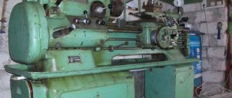
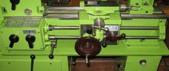
General view of the screw-cutting lathe 1I611P
Photo of screw-cutting lathe 1i611p
Photo of a screw-cutting lathe 1i611p in the museum of the IzhMash plant
Photo of screw-cutting lathe 1i611p
Photo of screw-cutting lathe 1i611p
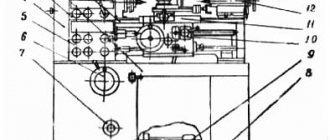
Location of controls for screw-cutting lathe 1i611p
Location of controls for screw-cutting lathe 1i611p
Specification of controls for screw-cutting lathe 1I611P
- Flywheel for preselective selection of spindle speeds;
- Handles for switching feeds and threads;
- Handles for switching feeds and threads;
- Handles for switching feeds and threads;
- Handle for switching the bit and the step increasing link;
- Shift knob;
- Manual longitudinal feed flywheel;
- Manual cross feed handle;
- Handle for securing the cutting head;
- Handle for turning the lead screw on and off;
- Cooling system fixation handle;
- Toggle switch “Lighting”;
- Handle for moving the upper slide;
- Quill clamp handle;
- Handle for securing the tailstock to the frame;
- Feed reversal handle;
- Quill movement flywheel;
- Nut for securing the tailstock to the frame;
- Start and stop handle;
- Safety mechanism adjustment handle;
- Main movement "Table" button;
- Main movement start button;
- Batch switch “Cooling”;
- Batch switch “Network”;
- Spindle speed shift handle.
Table of threads and feeds of lathe 1i611p
Table of threads and feeds of lathe 1i611p
Table of threads and feeds of lathe 1i611p
Table of threads and feeds of lathe 1i611p
Kinematic diagram of screw-cutting lathe 1I611P
Block diagram of the machine 1i611p (to kinematic diagram 2.)
Kinematic diagram of screw-cutting lathe 1i611p
The kinematic diagram of the machine is shown in Fig. 39.
The VII spindle is driven by an electric motor (N = 2.8 kW, n = 1430 rpm) through a gearbox and headstock mechanism. Shaft I of the gearbox receives rotation from the electric motor through a gear coupling M1. Two rotation speeds of 27/39 or 31/36 are transmitted to shaft II; Shaft III receives four rotation speeds through 36/44 or 27/53 gears. 16 rotation speeds can be transmitted to shaft IV through gears 19/61, 31/49, 49/31 or 53/27.
The locking of gear engagement is ensured by a preselective control mechanism (see Fig. 26, c). Rotation from shaft IV of the gearbox is transmitted to shaft V of the headstock through a V-belt drive d1 = 133, d2 = 135. From shaft V, rotation to the spindle can be transmitted directly through the M2 coupling or gear set (30/60) (18/72).
Thus, the spindle can receive 32 rotation speeds (2x2x4 + 2x2x4 = 32). In fact, the operating speeds are lower, since some of them are repeated.
In order to better imagine the kinematic dependencies of the main movement mechanism, we present the calculation of the lowest and highest spindle rotation speed.
Lowest rotation speed:
nmin = 1430 (27/39) (27/53) (19/61) (133/135) (30/60) (18/72) = 20 rpm
Highest rotation speed:
nmax = 1430 (31/36) (36/44) (49/31) (133/135) = 2000 rpm.
Similarly, you can calculate all other spindle speeds.
Rotation to the feed mechanism can be transmitted from the spindle through 48/68 gears, in the case of cutting a normal thread pitch, and through 48/68 gears from shaft V, in the case of cutting an increased thread pitch (increasing pitch link). The pitch of the cut thread can be increased eight times. Next, the rotation in shaft VIII is transmitted to the replacement wheels (a/d) (c/d) through a reversing mechanism and by transmission to gears (34/36) (36/44) or 34/44. From the guitar of interchangeable rings, rotation is transmitted to the XI shaft of the feed box.
The feed box is a standard mechanism with moving blocks and gear couplings.
The setting for threading and feed involves transmitting rotation from shaft XI to shaft XII, then to shaft XIII, XIV, using the appropriate engagement of gear tracks and the position of gear couplings M3, M4 and M5. Rotation from shaft XIV is transmitted to shaft XV of the transmission mechanism rotation onto the drive shaft or lead screw. Rotation to the lead screw XVII with a pitch of t = 6 mm is transmitted when the couplings M6 and M7 are engaged through the shaft XIV and XV or through gears (26/52) (33/55).
Rotation on the XVIII drive shaft is carried out through 48/40 gears with the M7 clutch disconnected.
When configured for cutting precise threads, movement to the lead screw XVII is transmitted directly through shafts X, XI, XIV, XV with the MZ, M5, M6, M7 couplings engaged, bypassing the feedbox mechanism. From the XVIII running shaft, rotation through gears 22/29 and the M8 coupling is transmitted to the XIX shaft of the apron mechanism. Through a 1/24 worm gear, the XX shaft receives rotation. The movement on the rack pair z = 15, m = 2 mm of longitudinal feed is transmitted through gears 15/39, coupling M10, gears 18/66; or through 15/39 gears, M9 coupling, 18/66 gears. The movement to the cross feed lead screw with a pitch t = 3 mm is transmitted through gears (15/39) (39/39) (39/33), M12 coupling, gears (36/18) (29/16) or through gears wheels (15/39) 39/39) (39/33), M11 coupling, gears (36/18) (29/16). The couplings M9, M10, M11, M12 are controlled by mnemonic handle 21 (see, Fig. 38), which enables forward and reverse movement of the caliper with the corresponding feed.
Layout of bearings on a lathe 1I611P
Layout of bearings on a lathe 1I611P
List of bearings on the 1I611P lathe
List of bearings on the 1I611P lathe
Purpose of the machine and features of its design
Despite the fact that the lathe of this model (the full abbreviation looks like this: IZH 1I611P) was developed back in the 60s of the last century, its technical capabilities today allow it to be used for various, including critical, metal work :
- turning, performed in cam or collet chucks, centers;
- milling;
- for grinding external and internal surfaces;
- performed by an end tool fixed in a drill chuck.
The characteristics of the 1I611P lathe allow it to process workpieces of cylindrical and conical shapes, and cut various types of threads: metric, inch, modular.
- The cutting head is fixed according to the backlash-free principle, which ensures its exceptional rigidity and, accordingly, high processing accuracy.
- To cut threads (metric, inch and modular) with various parameters, there is no need to change the gears in the machine’s guitar, which ensures the versatility of its feed box.
- The unit is designed with a welded container in which a coolant tank and all electrical equipment are installed.
- The chip removal system, collected in a volumetric chip collector, has a well-thought-out design.
Controls of the machine 1I611P
- While processing on the 1I611P lathe, the operator can pre-select the spindle rotation speed to be used at the next processing stage (preselective control).
- The 1I611P apron is equipped with a stopping mechanism that protects the feed box from overloads and also allows turning operations to be performed using a hard stop.
- The drive belts, which drive the spindle assembly, can be replaced without disassembling it.
- Precise movement of the caliper in the transverse direction is ensured by a special mechanism - vernier.
- A mechanism can be installed on the transverse carriage of the caliper to allow milling work.
- In cases where the lead screw is used (threading), it is lubricated automatically.
Schematic diagram of the machine (click to enlarge)
- The cast iron from which the 1I611P frame is made has a special composition - chromium-nickel, and its guides are carefully polished and hardened using high-frequency currents.
- The caliper feed control, for which one handle is responsible, is carried out according to a mnemonic principle: the direction of movement of this unit coincides with the direction in which the control handle is tilted.
- To protect the feed mechanism from overload, a special safety device is provided in its design.
- The design of the lathe in question is designed in such a way that there are no components on its rear side that need to be serviced. Thanks to this design feature, you can install the 1I611P machine even close to the wall.
Design of the main components of the screw-cutting lathe 1I611P
Gearbox
Gearbox of screw-cutting lathe 1i611p
The gearbox, installed on the left side of the cabinet, is a four-axis gearbox driven by a flange electric motor. The gearbox has flat guides for moving along the pedestal guides when the belt drive is tensioned and is secured using plates with mounting bolts.
Changing the speed of rotation is carried out by a preselective device, which allows you to select the number of revolutions during operation of the machine. The selection of speeds is made by means of a flywheel, by turning which a certain combination of holes is created in two disks for the fixing fingers of the levers that switch the gear blocks.
The speed switching is carried out as follows: first, the required number of spindle revolutions is set using the flywheel; at the desired moment, switching is carried out using the handle in two stages - first, the handle is pulled towards you until a noticeable force appears, holding the handle in this position, wait until the number of spindle revolutions decreases ( no higher than 100 rpm), then the handle is pulled back all the way, thus turning on the required speed.
When working at low spindle speeds (below 100 rpm), switching on can be done immediately - by moving the handle all the way. If, for some reason (the engine stopped, etc.) after the first attempt, the switching did not occur, you must release the handle and repeat the switching again.
Headstock
Headstock of screw-cutting lathe 1I611P
Headstock of screw-cutting lathe 1i611p
Headstock of screw-cutting lathe 1i611p
There is a pulley in the middle of the headstock on the sleeve. The movement to the spindle from the gearbox is transmitted by four V-belts. The machine spindle receives 12 revolutions from the take-up pulley directly through a gear coupling and 12 through a 1:8 ratio. On the front wall of the headstock (on the right) there is a handle for shifting the overdrive gears and the gear coupling. The control of the overdrive and the gear coupling are interlocked so that their simultaneous activation is impossible. To avoid crushing the ends of the gears, switching gears on the fly is not recommended.
In the headstock body there is a pitch increase link (8:1) and a snaffle, from which rotation is transmitted through the guitar to the feed box.
Spindle bearings for lathe 1I611P
The spindle of the 1I611P machine is mounted on three bearings:
- 13. Rear bearing No. 4-46209 - single-row angular contact ball, accuracy class 4, size 45x85x19
- 14. Rear bearing No. 2-8109 - thrust ball, accuracy class 2, size 45x65x14
- 15. Front bearing No. 4-3182112 - double-row roller, accuracy class 4, size 60x95x26 mm
Spindle bearing adjustment:
Adjustment of machine spindle bearings 1I611P
Adjustment of the radial clearance of the front spindle bearing is carried out as follows:
The outer ring of the bearing is installed in the housing, after which the inner diameter of the ring is measured - D.
The inner ring of the bearing with rollers is installed on the conical neck of the spindle and tensioned using a bushing with a long direction until the diameter along the grooves reaches the value D + (2...3 µm).
After this, the sleeve is removed and the bearing is fixed with nut 133.
The axial clearance in the rear bearings is adjusted using nut 117A through disk 115. To do this, press the front center in the direction of the spindle axis and tighten nut 117A and disk 115 until they touch the bearing, maintaining smooth rotation.
Technical characteristics of bearing No. 46209
Bearing 46209 is a single-row angular contact ball bearing of the main design.
Designed to absorb both types of loads acting in the nodes of mechanisms - both radial and axial. This type is very rarely produced at the leading plant for the production of angular contact bearings - 3 GPZ and only in the form of modification 6-46209L. Bearings of high precision levels can only be purchased from storage. You may also encounter this type (with the same degree of accuracy) produced by GPZ 20 (Kursk) and SPZ-4 (Samara). But the quality of the products from these factories is not so good.
In addition to high-precision equipment and machine tools (most of which, unfortunately, are practically no longer used by modern domestic industry), bearings of this type are used in automotive equipment, for example, this type is installed on the rear axle of the ZIL-133 truck.
Imported bearings of this type are marked 7209A. The brass separator in the number is reflected by the presence of the letter M, and the polyamide separator - the letter D.
Dimensions and characteristics of bearing 46209 (7209):
- Inner diameter (d): – 45 mm;
- Outer diameter (D): – 85 mm;
- Width (height) (H): – 19 mm;
- Weight: – 0.404 kg;
- Ball diameter: – 13.494 mm;
- Number of balls in the bearing: – 13 pcs.;
- Outer ring flange diameter: – 72.6 mm;
- Inner ring flange diameter: – 57.4 mm;
- Dynamic load capacity: – 38.7 kN;
- Static load capacity: – 23.1 kN;
- Rated rotation speed: – 8500 rpm.
Diagram of bearing 46209 (7209) of lathe 1I611P
Technical characteristics of bearing No. 8109
Bearing 8109 is a thrust ball bearing of the main design and is designed to support exclusively axial loads at low speeds.
One of the rings in bearings of this type has an internal diameter 1 mm larger (the one installed in the housing) than the other (mounted on the shaft) and they should never be confused, otherwise the service life of the entire product will be significantly reduced. In the Russian Federation, they are produced or were produced in the recent past at 20 gas processing plants (KZUP, Kursk), SPZ-4 (Samara) and gas processing plant-2 (Moscow). If the bearing has a marking different from the markings of these factories (and the world famous brands KOYO, NACHI, FBJ, SKF), the bearing is most likely Chinese and will not last long.
It is used quite widely in agricultural machinery, all kinds of machines and mechanisms.
Imported bearings (as well as Chinese and GPZ-2) are designated 51109.
Dimensions and characteristics of bearing 8109 (51109)
- Inner diameter (d): – 45 mm;
- Outer diameter (D): – 65 mm;
- Width (height) (H): – 14 mm;
- Weight: – 0.148 kg;
- Ball diameter: – 7.144 mm;
- Number of balls in the bearing: – 22 pcs.;
- Dynamic load capacity: – 24.2 kN;
- Rated speed: – 4500 rpm.
Diagram of bearing 8109 (51109) of drilling machine 1I611P
Technical characteristics of bearing No. 4-3182112
Bearing 3182112 is a double row radial roller bearing, with short cylindrical rollers, with a flangeless outer ring (as a result of which the set of rolling elements on the cage is able to move and create a “floating” support), with a tapered bore (1:12), a groove and holes for adding lubricant.
The main place of operation of such bearings is machines for various applications, units where high radial loads and speeds are applied. This standard size, like most roller bearings in this series, is currently produced only with high precision. The bearing has always been produced at the Moscow plant GPZ-1, but now its production is transferred to Volzhsky, to a branch of the Aviation Bearing Plant at 15 GPZ (all plants are united under the auspices of the European Bearing Corporation). Several modifications are manufactured, differing in accuracy class and separator material. The letter K means the presence of an annular groove and three holes for introducing lubricant, E - a polyamide separator. You can buy bearings with a quality guarantee only from official representatives of the EPK, which are located in many regions of the country, since the vast majority of other companies sell illiquid products that may work well, but more often than not. The estimated price of new factory products is up to 3,800 rubles.
Imported bearings of this size are designated NN3012K (the presence of the letter K in the number is mandatory, as it indicates a tapered fit). Products of different price categories are supplied to Russia: the most expensive and reliable are FAG, SKF, the cheaper ones are NACHI and NSK. An even cheaper option is the products of Eastern European manufacturers - ZKL and FLT, which are most often sold of illiquid quality, sometimes even used, produced in the 80s of the last century. The approximate price of the highest quality and most expensive imported bearings of this type is about 280 euros; they are either in the warehouses of companies or supplied to order.
Dimensions and characteristics of bearing 3182112 (NN3012K)
- Inner diameter (d): – 60 mm;
- Outer diameter (D): – 95 mm;
- Width (H): – 26 mm;
- Weight: – 0.69 kg;
- Roller dimensions: - 8x8 mm;
- Number of rollers: - 48 pcs;
- Dynamic load capacity: - 74.5 kN;
- Static load capacity: - 108 kN;
- Maximum rated speed: - 10000 rpm.
Bearing diagram 3182112 for lathe 1I611
Photo of bearing 3182112 (NN3012K)
Gearbox
Feed box for screw-cutting lathe 1i611p
A closed-type feed box allows, without the use of replaceable gears, to cut metric threads of all standard pitches from 0.2 to 48 mm, inch threads with the number of threads per inch from 24 to 0.5, modular threads with a module of 0.2-30 mm and receive feeds in ranging from 0.02 to 6 mm/rev. The amount of transverse feeds is equal to half of the longitudinal ones.
For cutting high-precision threads, the feed mechanism allows for direct connection of the lead screw to the guitar, bypassing the feed mechanism. Moreover, each step is selected only by the guitar’s replaceable gears.
Guitar
The guitar is mounted on the left side of the feed box. The general gear ratio of the feed chain from the spindle to the 1st drive shaft of the guitar is 1:2.
The guitar's 5:8 gear ratio translates to a metric thread setup. For cutting modular, inch and high-precision threads (bypassing the feedbox mechanism), the guitar has the ability to install replaceable gears.
The manual provides data for setting up the machine for cutting high-precision threads, as well as special threads not listed in the feed mechanism settings table.
Design features
The machine has the following design features:
- Fixation of the cutting head, but without gap (ensuring rigidity and accuracy).
- There is a container with a container for coolant and a cabinet with electrical equipment.
- Chip removal and collection system.
- Preselector control (preliminary selection of spindle speed for the next processing stage).
- Apron with overload protection and rigid stop when turning.
- Vernier mechanism for precise cross feed.
- On the transverse carriage of the caliper there is a mechanism for performing milling work.
- The caliper is controlled by one handle using a mnemonic principle.
- Lack of controls on the back side (can be placed against a wall).
bed
- Made of chromium-nickel cast iron with two flat and two prismatic guides, which are hardened by high-frequency currents and ground. The frame is fixed to a monolithic pipe. There is also a shelf that protects the lead screw from chips and emulsion. Inside the frame there are:
- Main drive electric motor.
- Reducer for changing spindle rotation speeds.
- Mechanisms of the lubrication and coolant supply system.
- Emulsion container.
- Panel with electrical equipment.
Headstock and tailstock
The front headstock contains:
- spindle unit connected to the gearbox by four V-belts;
- a gear coupling transmitting twelve rotation speeds to the spindle;
- overkill - transfers twelve more using a special handle;
- locking mechanism (prevents simultaneous activation of the clutch and overdrive);
- device for changing the pitch of the thread being cut;
- a bit that transmits rotation to the guitar and then to the gearbox.
The tailstock firmly tightens long parts and increases the accuracy of work. On this machine it can be shifted by 10 mm in both directions in relation to the centers.
Gearbox
Manufactured in closed form. Serves to supply movement to the support for cutting metric threads with a pitch of 0.2–48 millimeters without additional gears.
Gearbox
It is a gearbox consisting of four axles with gears. It is connected to the engine using flanges. The tension is regulated by thumbs.
Gearbox
Responsible for the rotation speed of the spindle assembly. It is driven by the main electric motor connected to it through flanges. The gearbox can be moved along flat guides to regulate belt tension. The speed change is carried out by a preselective mechanism controlled by a corresponding flywheel.
Caliper and apron
A support is a mechanism for attaching and moving tools and accessories for processing parts. The design allows the tool holder installed in the upper part to move in any direction. The longitudinal movement is provided by the carriage, and the transverse movement is provided by the slide.
The apron is located at the bottom of the caliper. The device is responsible for the longitudinal and transverse feed of the caliper. Movement is possible in manual and automatic mode. The apron contains:
- four clutches - control the direction of feed;
- drive shaft - produces translational movement of the caliper;
- the lead screw moves the carriage in the longitudinal direction;
- feed control panel;
- A locking device that makes it impossible to turn on the propeller and the drive shaft at the same time;
- Overload protection mechanism.
Spindle
The spindle is a hollow shaft with a conical hole. Rigidly mounted on bearings in the headstock. Has an internal Morse taper for fastening tools (for example: collet clamps). On the outside there is a thread for attaching a faceplate with a chuck.
High-quality fastening of the spindle bearings is important.
Electric scheme
The electrical circuit contains:
- The main drive is a three-phase asynchronous motor with a power of 3 kW.
- Drive motor for the lubrication supply mechanism.
- Coolant pump motor.
- A transformer that produces a voltage of 36 V for the lighting lamp, 60 V for the braking system and 127 V for the control circuits.
- Protection devices and thermal relays.
Features of additional parts
Some components are designed differently from other lathes.
In the headstock:
- the pulley is installed in the center;
- the spindle unit has twenty rotation speeds;
- guitar to expand types of thread cutting;
- bit with devices for increasing the step size.
The tailstock securely clamps the long workpiece. Can be moved 1 cm on both sides from the center. Expands the range of types of parts processing. The tapered ruler on the caliper makes it possible to process tapered parts.
Kinematic diagram
Electrical equipment of screw-cutting lathe 1I611P
Electric motors and equipment are designed to be connected to a network with a voltage of 380 V and a frequency of 50 Hz. The local lighting voltage is 36 V and the control circuit is 110 V. For dynamic braking, the voltage is 60 V DC.
The machine is equipped with three three-phase asynchronous electric motors:
- Main drive electric motor M1, power 3 kW, 1430 rpm, type 4A100S4 asynchronous three-phase
- Electric motor of lubrication pump M2, power 0.08 kW, 1390 rpm, type AOL012-4
- Cooling pump electric motor M3, power 0.125 kW, 2800 rpm, pump PA-22
Electrical circuit of lathe 1i611p (1968)
The electrical circuits of early and later modifications of the machines have minor differences, which are due to the use of more modern components: see the 1968 diagram and the 1975 diagram.
Electrical circuit of lathe 1i611p (1975)
Location of electrical equipment on a lathe 1i611p
List of elements of the electrical circuit of the screw-cutting lathe 1i611p
Description of the operation of the electrical circuit of the machine 1i611p 1975
The electrical part of the machine (Fig. 15-16) is connected to the network using the BC switch. When you press the Kn2 button, the magnetic starter KM is turned on, which turns on the lubrication electric motor M2.
Then, by moving the control roller handle to the upper position, switch VK1 is pressed, turning on the starter KB (forward). The latter will turn on the main drive motor M1. When the roller handle is moved to the lower position, switch VK2 is pressed, which will turn on the starter KN (backward), while the electric motor Ml will be provided with reverse rotation.
When the control roller is installed from the upper or lower position to the neutral position, the time relay PB will turn on through normally closed contacts 3-21, 21-23, 23-25, 25-27. The time relay with its normally open contact will turn on the CT brake starter, and the other closed contact PB with a time delay will open the circuit of this starter. The delay value is adjusted to the time required to completely stop the main drive electric motor Ml, but not more than 2.5 seconds, since setting for a longer time can lead to failure of the selenium rectifier and transformer. Electrodynamic braking occurs by supplying direct current from a selenium rectifier CB to the stator winding of an electric motor. Limit switch VK3 serves to slow down the electric motor M1 at the moment of switching gears of the gearbox on the move. The electric cooling pump is turned on by the HV switch when the lubrication electric motor M2 is running. The lighting is turned on by the VO switch.
Protection and blocking
- Protection of the electrical equipment of the machine from short circuits is provided by fuses Pr1, Pr2. PrZ, Pr4.
- Protection of electric motors M1 and M2 from overload is carried out by thermal relays PT1 and PT2.
- Zero protection of the circuit is provided by the KM starter. The circuit provides for electrical interlocking of magnetic starters in order to exclude the possibility of their simultaneous activation.
Instructions for installation and operation of electrical equipment
When installing, the machine must be reliably grounded, i.e. connected to the general grounding system of the workshop. The grounding bolt and power input are located behind the machine at the bottom of the cabinet.
Before starting electric motors, you should:
- Measure the insulation resistance, measure with a megohmmeter at a voltage of 500 volts. The permissible insulation resistance of the stator windings must be at least 0.5 MOhm. An electric motor with a winding insulation resistance below 0.5 MOhm must be dried.
- Check the correct rotation of the electric motors: when you turn on the handle 19 (Fig. 7), there should be a direct rotation of the spindle upward. If it rotates incorrectly, it is necessary to swap any two phases of the machine's power supply.
To ensure normal operation of the electric motor, the switching frequency should not exceed four per minute, and the reversing frequency should not exceed two per minute.
When operating electric motors, it is necessary to pay attention to their lubrication. Check the ball bearings at least twice a year and replace the old grease with new one. Bearings should be washed with gasoline; the use of kerosene is not allowed. In case of severe wear, the ball bearings must be replaced with new ones.
Electric motors and equipment must be regularly cleaned of dust and dirt with a dry cloth. To avoid corrosion of the insulation layer, it is not allowed to wash the windings of electric motors with gasoline or kerosene.
At least once a decade, you should check the condition of contact connections and wires supplying current to electric motors.
It is also necessary to check the tightness of the ground bolt contact. Monitor the serviceability of magnetic starters, promptly clean burnt contacts with an emery cloth or a velvet file. Contacts must not be lubricated. Worn contacts must be promptly replaced with new ones.
Corrosion on the magnetic circuits of electric devices causes increased humming, so their working surfaces must be periodically lubricated with machine oil and then wiped dry.
It is not recommended to turn off the machine using the BC switch while it is running.
If the electric motor is turned off by the thermal relay, it is necessary to identify the cause and, after a 15-minute break, turn on the thermal relay using the return button. Only after this can you continue working.
Thermal relays are adjustable within 25% of the rated current.
When inspecting or repairing electrical equipment, the BC switch must be turned off.
Note. When operating the machine with frequent starts or reverses, it is necessary to set the current regulator of the thermal relay PT1 to positive to the maximum or to bypass the heating elements.
How to operate the machine
Attention should be paid to safety precautions. Initially, the pump is turned on, and only then, after lubricating the parts, the electrical network is turned on. Failure to comply with this rule may result in a short circuit and is unsafe for the specialist.
Opening hours are not indicated in the passport. The machine is of a professional type, so it can work uninterruptedly for several hours. The main thing is to ensure that the parts are lubricated.
1I611P - universal equipment for industrial purposes. But it is found in home workshops. When choosing a device, carefully check its technical characteristics in practice yourself.
Technical characteristics of screw-cutting lathes 1I611P
| Parameter name | IZH-250P | 1I611P | 250-ITV | 250ITVM.01 |
| Main settings | ||||
| Accuracy class according to GOST 8-82 | N, P | P | IN | IN |
| The largest diameter of the workpiece installed above the bed, mm | 250 | 260 | 300 | 300 |
| The largest diameter of the workpiece processed above the bed, mm | 250 | 250 | 240 | 240 |
| The largest diameter of the workpiece above the support, mm | 125 | 125 | 168 | 168 |
| Maximum workpiece length (RMC), mm | 500 | 500 | 500 | 500 |
| Maximum turning length, mm | 500 | |||
| Center height, mm | 150 | 135 | 150 | 150 |
| Cutter height, mm | 20 x 20 | 16 x 16 | 16 x 16 | 16 x 16 |
| Spidel | ||||
| Diameter of through hole in spindle, mm | 33 | 25 | 25 | 25 |
| Maximum rod diameter, mm | 30 | 24 | 24 | 24 |
| Number of speed steps for direct spindle rotation | 22 | 21 | 18 | 21 |
| Spindle direct rotation frequency, rpm (number of steps) | 16..2000 (22) | 20..2000 (21) | 63..3150 (18) | 25..2500 (21) |
| Size of the internal cone in the spindle (GOST 13214) | Morse 5 | Morse 4 | Morse 4 | Morse 4 |
| Spindle braking | There is | There is | There is | There is |
| Spindle end according to GOST 12593-72 | M68x6 | 4 | 4K | 4 |
| Submissions | ||||
| Maximum stroke length of the carriage, mm | 500 | 500 | 500 | 500 |
| Maximum lateral movement of the caliper, mm | 150 | 180 | 170 | 165 |
| Longitudinal movement of the caliper per one revolution of the dial, mm | 23,5 | 20 | 20 | |
| Price for dividing the longitudinal movement dial of the caliper, mm | 0,1 | 0,1 | 0,1 | 0,1 |
| Dividing value of the caliper transverse movement dial, mm | 0,05 | 0,02 | 0,02 | 0,05 |
| Transverse movement of the caliper per one revolution of the dial, mm | 3 | 3 | 2 | 3 |
| Number of longitudinal feed stages | 25 | 24 | 21 | |
| Limits of longitudinal working feeds, mm/rev | 0,02..2,17 | 0,01..3 (25) | 0,01..1,5 | 0,01..1,8 |
| Number of cross feed stages | 25 | 24 | 21 | |
| Limits of working cross feeds, mm/rev | 0,01..1,08 | 0,005..1,5 | 0,005..0,75 | 0,005..0,9 |
| Speed of fast movements of the caliper, longitudinal, m/min | No | No | No | No |
| Maximum permissible traction force, N (kg) | 5000 (500) | |||
| Number of metric threads to be cut | 33 | 30 | 33 | |
| Limits of pitches of cut metric threads, mm | 0,2..6 | 0,2..48 (33) | 0,2..24 (30) | 0,2..48 (33) |
| Number of inch threads to be cut | 26 | 21 | 26 | |
| Limits of pitches of cut threads, inch, threads per inch | 24..3,5 | 24..0,5 (26) | 24..1 (21) | 24..0,5 (26) |
| Number of modular threads to be cut | 35 | 21 | 25 | |
| Limits of pitches of cut modular threads, modules | 0,2..6 | 0,2..30 (35) | 0,2..6 (21) | 0,2..12 (25) |
| Limits of pitches of cut pitch threads | No | No | No | No |
| Upper Caliper Slide (Cutter Slide) | ||||
| Maximum movement of the slide, mm | 120 | 120 | 120 | |
| Price for dividing the slide movement dial, mm | 0,1 | 0,05 | 0,02 | |
| Movement of the slide per one revolution of the dial, mm | 3 | |||
| Thread indicator | No | No | No | No |
| Blocking | There is | There is | There is | There is |
| Overload protection | There is | There is | There is | There is |
| Switching stops longitudinal / transverse | yes/no | There is | There is | There is |
| High speed | No | No | No | No |
| Tailstock | ||||
| Center in tailstock quill | Morse 3 | Morse 3 | Morse 3 | Morse 3 |
| Maximum movement of the tailstock quill, mm | 90 | 85 | 85 | |
| The price of division of the ruler / dial for moving the tailstock quill, mm | 1/ 0,05 | 1/ 0,05 | ||
| Transverse displacement of the tailstock, mm | ±10 | ±10 | ±10 | ±10 |
| Electrical equipment | ||||
| Number of electric motors on the machine | 3 | 3 | 3 | 3 |
| Main drive electric motor power, kW (rpm) | 2,6/ 3 (1420/ 2800) | 3 (1420) | 3 (1430) | 3 (1410) |
| Main drive motor type | FT-42-4/2 | AOL2-32-4 | AIR100S4PU3 | |
| Lubrication station electric motor power, kW (rpm) | 0,18 (1400) | 0,08 (1390) | 0,09 (2700) | 0,09 (1350) |
| Hydraulic motor type | AOL-012-4 | AOL-012-4 | ||
| Lubrication station type | S48-12M | |||
| Cooling pump electric motor power, kW (rpm) | 0,125 (2800) | 0,15 (2800) | 0,12 (2800) | 0,18 (3000) |
| Cooling pump (pump) | PA-22 | PA-22 | PA-25MS | |
| Dimensions and weight of the machine | ||||
| Machine dimensions (length width height), mm | 2030 x 875 x 1220 | 1770_970_1300 | 1790_810_1400 | |
| Machine weight, kg | 1570 | 1120 | 1180 |
- High precision screw-cutting lathe, model 1I611p. Manual for the machine, Izhmash, 1975
- High precision screw-cutting lathe, model 1I611p. Manual for the machine, Izhmash, 1968
- Acherkan N.S. Metal-cutting machines, Volume 1, 1965
- Batov V.P. Lathes, 1978
- Beletsky D.G. Handbook of a universal turner, 1987
- Denezhny P.M., Stiskin G.M., Thor I.E. Turning, 1972. (1k62)
- Denezhny P.M., Stiskin G.M., Thor I.E. Turning, 1979. (16k20)
- Lokteva S.E. Computer controlled machines, 1986
- Modzelevsky A. A., et al. Lathes, 1973
- Pikus M.Yu. A mechanic's guide to machine repair, 1987
- Skhirtladze A.G., Novikov V.Yu. Technological equipment for machine-building industries, 1980
- Tepinkichiev V.K. Metal cutting machines, 1973
- Chernov N.N. Metal cutting machines, 1988
Bibliography:
Related Links. Additional Information
- Classification and main characteristics of turning
- Selecting the right metalworking machine
- Multi-start thread. Methods for cutting multi-start threads on a lathe
- Graphic signs for lathes
- Friction clutch of a screw-cutting lathe
- Methodology for checking and testing screw-cutting lathes for accuracy
- Manufacturers of lathes
- Manufacturers of metal-cutting machines
- Directory of lathes
Home About the company News Articles Price list Contacts Reference information Interesting video KPO woodworking machines Manufacturers
Purpose and scope
The 1P611 screw-cutting lathe was designed for operation in premises that do not have solid poured foundations under the equipment. It is used in multi-storey industrial premises and installed in mobile workshops, including steamships. The design of the frame dampens vibration. Technological accuracy does not depend on the position of the equipment. The machine operates stably even when the floor tilts.
The purpose of 1P611 is the production of small series and single parts from steel, cast iron, non-ferrous metals and their alloys. The machine performs roughing of workpieces and finishing of parts with high precision and cleanliness.
Surface treatment
The machine performs cutting of cylindrical and conical surfaces, end processing and thread cutting. Cutters and multi-edge tools are used:
- incisors;
- drill;
- countersink;
- taps and dies.
If it is necessary to strengthen the surface and give it a high class of cleanliness, rolling in with a roller, cleaning with a file and sandpaper is possible. To perform these operations, simple devices are used.
Threading
The guitar is set to the correct gear ratio for thread cutting. Each set of gears corresponds to a specific pitch. The shape of the thread is ensured by sharpening the cutter according to a template.
On model 1P611 threads are cut:
- metric;
- modular;
- inch.
Pipe - conical, made using a special tool.
Threads with a diameter of up to 24 mm, located from the end, are cut with a multi-blade bench tool:
- tap for the inner surface, nut type parts;
- die for external thread: bolts, studs.
To cut them, the tool is mounted on the tailstock.
In areas where it is impossible to use a metalworking tool, the thread is cut with a cutter. To remove the tool, a groove is provided in the drawing.
Important!
The cutter is retracted manually. The turner requires high qualifications to perform the operation: at the same time, the handle of the slide rotates, and the revolutions and feed are turned off with a lever on the apron.
Drilling
On a 1P611 screw-cutting lathe, drilling is performed in the axis of rotation of the part at the end on the tailstock side.
- The drill is inserted into the quill cone.
- The tool is brought to the part. The tailstock is fixed motionless.
- Reverse revolutions are activated.
- By rotating the handle, the quill moves and the drill cuts into the part.
When processing thin long shafts, a steady rest is installed for rigidity. Drilling large holes can take place in 2 stages: first a drill of a smaller diameter, then the required one.
Segment
On the 1P611 model there is no transverse mechanical feed of the cutter. The slide is moved manually using a handle. The cutter is aligned with the cutting edge exactly along the axis of the part. The spindle rotates and the cutting tool is brought in. Cutting with a straight cutter is done in reverse rotation.
Reaming holes
Holes are developed in short parts of large diameter, such as washers, rings, after drilling.
- The cutter is attached to the cutter holder with a stem along the axis of the part.
- Rotation starts.
- The part is processed by moving the caliper along the guides.
Important!
Thin parts are processed manually. With a mechanical feed, there is a high probability that you will not have time to stop the caliper and the tool will crash into the cams.
Countersinking
Long workpieces such as a shaft are clamped at one end in the cams. A steady rest is placed on the tailstock side to prevent beating. A countersink is installed in the quill. It cuts into the center of the end when rotating to a specified depth. Configuration – type, holes for centering, determined by the shape of the countersink.