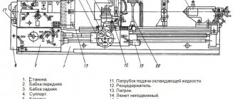
Information about the manufacturer of the educational screw-cutting lathe TV-7M
The manufacturer of the educational screw-cutting lathe TV-7m is the Rostov plant of small-sized machine tools MAGSO, KomTeh-Plus , founded in 1956.
The machines produced by this company are well known on the Russian market and a number of CIS countries, thanks to the first models of screw-cutting lathes TVSh, TVSh-2, TVSh-3, TV-4, TV-6, TV-7. Model TV-7M, deservedly enjoying the reputation of high-quality and reliable equipment. An important feature of the machine is its efficiency and low operating costs.
Machines produced by the Rostov plant of small-sized machine tools MAGSO
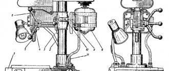
- NS-16 - tabletop drilling machine Ø 16
- NGF-110Sh3 - low power milling machine 0.6 kW, table size 100x400 mm
- NGF-110Sh4 - low power milling machine 0.75 kW, table size 100x400 mm
- SNVSH - tabletop drilling machine Ø 16
- SNVSH-2 - tabletop drilling machine Ø 16
- TV-4
- educational screw-cutting lathe Ø 200, RMC 350 mm - TV-6
- educational screw-cutting lathe Ø 200, RMC 350 mm - TV-6M
- educational screw-cutting lathe Ø 200, RMC 350 mm Dubno - TV-7
- educational screw-cutting lathe Ø 220, RMC 330 mm - TV-7M - educational screw-cutting lathe Ø 220 mm, RMC 275 mm
- TV-9 - educational screw-cutting lathe Ø 220 mm, RMC 525 mm
- TV-11 - educational screw-cutting lathe with frequency converter Ø 240, RMC 750 mm
Features of installation of the TV-7M machine and its first launch
Installation of the TV-7M educational turning and screw-cutting unit should be carried out on a table or a manufactured stand with a height of no less than 660 mm and no higher than 680 mm from the floor level. The height must be maintained in accordance with the relevant ergonomic requirements.
The cabinet can be made of wood, but to ensure sufficient rigidity of the base, metal corners and sheet metal are best suited. Before fixing the screw-cutting machine, it must be leveled in two planes.
Before using this machine for the first time, you must complete the following mandatory steps:
- carefully read the operating manual of the machine, study its design and safety rules during operation;
- clean non-paintable surfaces of the unit with napkins or rags soaked in solvent to remove the anti-corrosion coating;
- check the presence of grounding; if it is missing, then it must be done in accordance with the rules;
- fill the lubrication and oil filling points;
- check the position of all handles of the lathe control system (they must be in the neutral position);
- connect the power cable to the terminals of the terminal block.
At the initial stage, within 30–40 hours of operation of screw-cutting turning equipment, it is not recommended to perform turning operations at maximum spindle speed.
TV-7M table-top screw-cutting lathe for training. Purpose, scope
TV-7M screw-cutting lathe TV-7 model in production
.
The TV-7M machine is a desktop universal screw-cutting lathe and is intended for training in the profession of a turner, as well as performing all kinds of turning work with a part weight of 5 kg, including:
- grooving and boring of cylindrical and conical surfaces
- drilling
- segment
- thread cutting
- trimming ends
Operating principle and design features of the machine
The TV-7M universal screw-cutting lathe was designed more than 35 years ago and is currently being produced.
The TV-7M again acquired a 6-speed gearbox, which was removed from its predecessor, the TV-7 machine, in order to simplify the design.
the TV-7M screw-cutting lathe is mounted on three angular contact bearings - two in the front and one in the rear supports. The diameter of the hole for processing the rod is 18 mm
The front end of the spindle is threaded M45 x 4.5 for the intermediate flange GOST 3889 version 1. Standard chuck Ø100, Ø125 mm with the largest diameter of the clamped part Ø90 and Ø110 mm, respectively.
The feed box provides 8 mechanical feeds and 6 metric thread sizes without rearranging the guitar gears.
The traditional visual layout of the machine in combination with a proven kinematic diagram allows you to confidently provide turning with accuracy class “H” over a long service life.
Compared to small-sized machines offered on the market, it is easy to operate, reliable and durable.
The TV-7M machine differs from lathes and TV-9 and TV-11 in the center-to-center distance, RMC:
- TV-7M - RMC 275 mm
- TV-9 - RMC 525 mm
- TV-11 - RMC 750 mm
Model features
The universal training and production screw-cutting lathe KOMTECH TV-7M is designed for teaching the profession of a turner, as well as for performing all types of turning operations with a part weight of up to 5 kg, including:
- grooving and boring of cylindrical and conical surfaces;
- drilling;
- segment;
- thread cutting;
- trimming ends.
The traditional visual layout of the machine in combination with a proven kinematic diagram allows you to confidently provide turning operations over a long service life.
An important feature of the TV-7M machine is its efficiency and low operating costs.
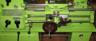
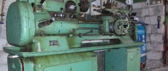
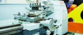
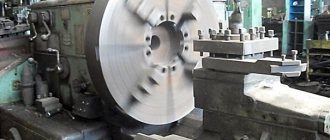
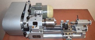
General view of the TV-7M screw-cutting lathe
Photo of screw-cutting lathe TV-7m
Photo of screw-cutting lathe TV-7m
Photo of screw-cutting lathe TV-7m
Photo of screw-cutting lathe TV-7m
Purpose of the TV-7M installation and its main components
The TV-7M screw-cutting machine is designed for training novice turners to process metal, plastic and wooden blanks and obtain cylindrical, conical and spherical shapes from them. With this equipment you can:
- make and bore surfaces;
- cut internal and external threads;
- drill;
- cutting and trimming ends.
The base of the TV-7M screw-cutting lathe consists of two stands with a pallet between them. In the front base cabinet, as a rule, a reduction box and an electric drive are installed on a common slide. The rear cabinet contains the electrical equipment of the machine, magnetic starters and fuses.
Location of components of the TV-7M screw-cutting lathe
Location of the components of the TV-7M lathe
Specification of components of the screw-cutting lathe TV-7M
- bed
- Headstock
- Tailstock
- Caliper
- Guitar
- Apron
- Gearbox
- Electric motor
- Switch
- Electrical cabinet
- Protective casing
- Protective shields
- Lamp
- Protective screen
Analogs
An analogue of the TV-7 machine is its improved model - TV-7m, manufactured by the above-mentioned plant in a desktop version.
Features:
- main dimensions of the model – 1120x640 mm, 1120x680 mm;
- electric motor performance – 750 W;
- the maximum distance for moving the headstock quill located at the rear is 65 mm;
- The diameter of the manufactured parts when they are fixed above the device body is 220 mm. The same above the caliper – 100 mm;
- length of the processed element installed in the central part – 275 mm;
- processing length of the part installed in the chuck – 250 mm;
- the height of the device serving as a holder for the cutter is 16x16 mm;
- maximum weight of parts to be processed – 5 kg;
- spindle head clearance diameter – 18 mm;
- the number of stages of rotation of the workpiece around the axis of the main shaft is 6.
In order to simplify the design, the TV-7m machine is equipped with several pairs of gears with different gear ratios. They, together with the shafts, convert the torque to a given parameter.
The following operations are performed on it:
- boring and grooving of surfaces of various shapes;
- cutting, drilling, trimming parts;
- trimming, cutting external and internal threads;
- grinding of manufactured parts.
Location of controls for the TV-7M screw-cutting lathe
Location of controls for the TV-7M lathe
Specification of controls for the TV-7M screw-cutting lathe
- Spindle speed setting knobs
- Spindle speed setting knobs
- Feed direction change handle
- Handle for setting the feed rate and thread pitch
- Handle for turning on the lead shaft and lead screw
- Handle for manual movement of the cross slide
- Cutting head mounting handle
- Handle for manual movement of the upper slide
- Tailstock quill fastening handle
- Handle for attaching the tailstock to the bed guides
- Handwheel for moving the tailstock quill
- Rack and pinion on/off button
- Lead screw nut engagement handle
- Longitudinal mechanical feed switch handle
- Handwheel for manual movement of the longitudinal carriage
- Machine emergency shutdown button
- Electric motor reversing handle
- Batch switch for local lighting
- Batch network switch
Equipment management
Since TV-7 was created for use as school or educational equipment, managing its operation does not present any great difficulties. Even from the photo of the device it is clear that it is not difficult to master the operation of such a unit.
TV-7 controls (click to enlarge)
The design of the turning TV-7 has several package-type switches; a button responsible for emergency stop of the work process; a button that starts the rack and pinion gear; flywheel to control the longitudinal movement of the carriage; a second flywheel, with which the tailstock is moved; as well as a number of management bodies responsible for carrying out such operations as:
- turning on the reverse mode of operation of the main engine;
- tension of the belt connecting the electric motor to the gearbox;
- starting the feed of the machine support in the longitudinal direction;
- fixing the tailstock on the bed guides;
- moving the slide in the transverse direction;
- change in feed direction;
- activation of the lead screw and the lead roller;
- changing the rotation speed of the spindle assembly;
- selecting the feed rate and pitch of the thread being cut.
The main purpose of TV-7 is to train young specialists
A review of the design of the unit will be incomplete without mentioning the three handles responsible for:
- turning on the lead screw nut;
- quill fastening;
- fixing the cutting head in the required position.
All of these controls allow you to effectively perform simple turning operations on metal workpieces.
Even from a brief overview of the TV-7 model lathe, it is clear that with the help of this device you can quickly master the basics of turning and the principles of managing metalworking technological operations.
TV-7M machine control
The machine's electric motor is started and stopped using handle 17 (see Fig. 2).
When turning handle 17 up, the engine rotates “Forward”; when turned down, the engine rotates “Backward”. In the middle position of the handle, the engine is turned off.
Depending on the nature of the work performed on the machine, the handles and control levers (see Fig. 2) must be in certain positions.
I. Position of handles and levers when working on thread cutting (mechanical feed with a lead screw):
- On the headstock - the position of the bit handle 3 depending on the direction of feed of the caliper (left or right).
- On the feed box - the position of handle 4 depending on the selected feed amount. Handle 5 “Screw - Shaft” in the left “Screw” position.
- On the apron is the handle of the self-propelled gun 14 in the lower off position “Push away”.
- The rack and pinion gear lever 12 is in the “Pull” position.
- The handle for turning on the uterine nut 13 is in the lower extreme position.
II. Position of handles and levers when working with the drive shaft (mechanical feed):
- On the headstock - the position of the reverse handle 3 depending on the direction of feed of the caliper (left or right).
- On the feed box - the position of handle 4 depending on the selected feed amount. Handle 5 “Screw-Shaft” in the right “Shaft” position.
- On the apron is the self-propelled handle 14 in the “Pull” position.
- The handle for turning on the uterine nut 13 is in the upper position.
- The rack and pinion gear lever 12 is in the “Push away” position.
III. Position of handles and levers for manual longitudinal feed:
- On the headstock - the position of the bit handle 4 is in the middle position.
- On the feed box, the position of the “Screw-Shaft” lever is indifferent.
- On the apron is the self-propelled handle in the off position. The lever of the uterine nut is in the upper position.
IV. The position of the control handles to obtain the required cutting conditions according to Fig. 12.
Mechanics of screw-cutting lathe TV-7M
Mechanics of screw-cutting lathe TV-7M
General idea of the TV-7 machine
The TV-7 screw-cutting lathe was produced in Rostov. According to the passport, it was intended to equip school workshops and vocational schools. Many schoolchildren and students learned turning on these machines.
General form.
Speeds are switched by a reduction gearbox with two modes and belt reversal. There are no levers for this purpose.
On TV-7 you can perform the following work:
- cut threads;
- cut off;
- sharpen;
- drill holes;
- trim the ends.
If you have experience and tools, a turner can perform some other types of work.
Design of the TV-7M screw-cutting lathe
The bed of the TV-7M screw-cutting lathe is cast, cast iron, box-shaped with windows. It has two prismatic and two flat guides.
The front prismatic and rear flat guides are used to move the caliper, and the rear prismatic and front flat guides are used to move the tailstock.
Headstock of screw-cutting lathe TV-7m
Headstock of screw-cutting lathe TV-7m
Drawing of the headstock of the TV-7M lathe
The headstock serves to secure or support the workpiece and impart rotational motion to it.
The headstock is mounted on the left side of the bed. In the TV-7M model machine, the headstock is also a gearbox, so this term will be used in the future.
Rotation to the input shaft 2 of the gearbox is transmitted from the electric motor by a V-belt transmission through pulley 1.
From input shaft 2 to shaft 3, rotation is transmitted by a gear pair with internal gearing 4 and 5.
Gear 6 and block gear 7 are fixedly fixed on shaft 3.
On shaft 8 there are block gears 9 and 10, which move along the shaft splines using handles 1 and 2 (Fig. 2). Handle 1 has three fixed positions, obtained by turning to the right and left.
Handle 2 has two positions.
The triple block gear 9 has the ability to mesh with gear 6 and block gear 7 and thereby transmit rotation to shaft 8 (three different speeds).
Rotation from shaft 8 to spindle 12 is transmitted through block gears 10 and 11.
Thus, the spindle has 6 speed levels (see Table 5) from 60 to 975 rpm.
The spindle transmits the rotation of the workpiece using a three-jaw chuck or a faceplate with a driver, which are screwed onto its threaded part. When machining parts on centers, a center is inserted into the spindle.
The feed movement of the caliper is borrowed from the spindle. Shaft 13 receives rotation through gears 14-15. From shaft 13 the movement is transmitted to the guitar gear - 17.
A device is mounted in the headstock that allows you to change the direction of movement of the caliper - to reverse the feed. Rotation is reversed by moving gear 15 to the left and right extreme positions using handle 3.
In the left extreme position, gear 15 will receive direct rotation directly from the gear block 14 located on the spindle.
In the right extreme position, gear 15 will receive reverse rotation through idler gear 16, which is in constant engagement with the second stage of gear block 14.
On the front side of the headstock housing there is an oil indicator 18. On the reverse side there is a plug 19 for draining the oil.
Guitar screw-cutting lathe TV-7M
The guitar (Fig. 5) serves to transmit rotation from the headstock spindle to the feed box.
The guitar assembly includes a bracket 6, two axles 5 pressed into it, on which the gears rotate freely.
Rotation from gear 1 sitting on the output shaft of the headstock is transmitted to the replacement gear, and then through gears 2-3-4 it is transmitted to the input shaft of the feedbox.
Feed box for screw-cutting lathe TV-7M
The movement from the spindle of the headstock of the machine through the transmission mechanism (guitar) is transmitted to shaft 1 of the feed box (Fig. 6).
When turning handle 4 (Fig. 2), which has three fixed positions, block gear 6 moves along the splines of shaft 5 and its rims alternately engage with gears 2, 3, 4, stationary on shaft 1 (Fig. 6) .
This makes it possible, together with the replacement gears of the guitar, to obtain a metric thread with a pitch of 0.8; 1.0; 1.25; 1.5; 2.0; 2.5 mm and longitudinal mechanical feed of the caliper 0.1; 0.12; 0.15; 0.16; 0.18; 0.20; 0.24; 0.32 mm/rev.
Apron
Using the apron (Fig. 7), you can perform mechanical longitudinal feed of the caliper from the lead roller and from the lead screw, as well as manual longitudinal feed.
Manual feed is carried out by rotating the flywheel 1, mounted on the pinion shaft 4, which engages with gear 3, sitting on the shaft of rack and pinion gear 2.
The rack and pinion meshes with a rack that is rigidly attached to the frame. Mechanical feed from the running roller 10 is carried out by a worm 5 connected to the roller by a sliding key. The worm causes the worm gear 11 to rotate and then through the cam clutch and gears 13, 3 the rotation is transmitted to the rack and pinion gear. To turn on the mechanical feed, you need to turn handle 6 towards yourself, and the claw clutch is turned on.
Support for screw-cutting lathe TV-7M
The support (Fig. is designed to secure and move the cutter. The support has four slides.
Slide 1 moves in the longitudinal direction along the frame guides.
Slide 2 moves along the transverse guides of slide 1 and serves to move the cutter transversely.
Slide 4, carrying a four-position cutting head, has only longitudinal movement along the guides of slide 3, which has the ability to rotate 40° from the average position in one direction or another.
Transverse movement of slide 2 along the guides of lower slide 1 is carried out by screw 6 and nut 5.
Screw 6 is rotated by hand using handle 12.
On top, slide 2 has a recess into which the protrusion of the rotating part of the upper support fits; To secure the rotating part, there are 2 bolts, the heads of which fit into the T-shaped groove of slide 2.
The upper slide 4 of the support can be moved along the guides manually using a handle 7, which rotates the screw 8. The guides of the frame, slides and wedges wear out so much from prolonged operation that a gap may appear between them.
Tailstock of screw-cutting lathe TV-7M
The tailstock serves to support the second end of the workpiece. Housing 1 is located on base 2, which moves along the guides of the machine bed.
The quill 3 is swept longitudinally in the body.
The quill has a conical hole (Morse taper 2) into which a stop center or other tool is inserted; drills, reamers, drill chuck, etc. The quill is moved by handwheel 4, which rotates screw 5.
Specifications
| The largest diameter of the workpiece, installed: - above the frame, mm - above the support, mm | 220100 |
| Maximum length of the workpiece, mm | 275 |
| Maximum length of the workpiece in the chuck, mm | 250 |
| Diameter of through hole in spindle, mm | 18 |
| Center in spindle, Morse | 3 |
| Pitch value of processed metric threads, mm | 0,8; 1.0; 1.25; 1.5; 2.0; 2,5 |
| Number of spindle speed steps | 6 |
| Spindle speed limits, min-1 rpm | 60/105/185/315/555/975 |
| Electric motor, kW/V | 0,75/380 |
| The value of longitudinal working feeds of the caliper, mm/rev | 0,1 ÷ 0,32 |
| Movement per dial division, mm—longitudinal—transverse | 0,250,025 |
| Quill center in Morse tailstock | 2 |
| Value of longitudinal working feeds of the caliper, mm | — 0,1; 0,12; 0,16; 0,20; 0,24; 0,32 |
| Largest cross-section of the cutter holder, mmwidthheight | 1616 |
| Quill center in tailstock, Morse | 2 |
| Overall dimensions of the machine, mm, no more | 1144x585x735 |
| Machine weight, kg, no more | 210±5% |
Lubrication system
A list of lubrication points is given in Table 7.
Lubrication of the main components of the machine
Careful attention to machine lubrication is a guarantee of trouble-free operation of the machine and its durability.
To lubricate the machine, industrial oil I-20 L, GOST 20799-75 and solid oil Zh, GOST 1033-79 should be used.
Headstock
The headstock gears and bearings are lubricated by splashing oil from an oil bath. Oil is added with the top cover removed.
The oil level in the headstock should be in the middle of the oil indicator eye.
Gearbox
To lubricate the feedbox mechanism, there is a tray for filling oil in its upper part. From the tray, oil is supplied to the gears and rubbing surfaces by wicks. While the machine is operating, there should always be a small amount of oil in the trough.
There is a drain plug at the bottom to drain accumulated oil.
Apron
The apron mechanism is lubricated manually through a hole in the lower carriage of the caliper.
The guides of the caliper bed, tailstock, lead screws and lead screw bearings are lubricated by hand.
To lubricate the lead screw and the lead roller, it is necessary to remove the protective shields installed on the apron body.
Lathe lubrication system
Timely lubrication of all working units of turning equipment is the key to long-term and trouble-free operation of the machine. In the lubrication system of the TV-7M training and production unit, industrial oil I-20A and Zh grade grease should be used.
The headstock bearings and gears are automatically lubricated by spraying oil from a special oil bath located in the unit housing. Oily liquid is poured into the bath when the top cover is removed. Lubricant control in the headstock is carried out using a special level indicator eye. The level should not be lower than the middle of the eye. The oil change is carried out for the first time after 10 days of operation, subsequent ones - every 40 days.
The feed box has a special place for filling with oil at the top of the unit. From this place, oil reaches the surfaces of rubbing parts and gears through a wick feed. When turning workpieces, there should always be some oil in this tray.
The accumulated grease in the lower part is drained using a drain plug. As a rule, you need to add lubricating fluid to the trough once every 5 days. The waste must be drained from the assembly body for the first time after 10 days, and subsequent times every 20 days.
The apron, caliper and tailstock mechanisms are lubricated by hand at least once per work shift. Lubrication of bearings, guides, as well as rollers and screws on the frame must be done manually at least once a month. The guitar must be lubricated by hand once a month of use.
Adjustment of the TV-7M machine
Eliminating axial play in the bearings of the front spindle support
Elimination of axial play in the bearings of the front spindle support is carried out using nut 1, which is secured against self-unscrewing by screw 2 (Fig. 13).
If spindle vibration occurs during operation of the machine, it is necessary to check the tightness of nut 1. If tightening the nut does not eliminate spindle vibration, this indicates that the bearings of the front spindle support are worn out and the machine requires repair.
The gap in the bearings of the front spindle support is eliminated by grinding the ends of the compensation ring 3.
Belt tension
To extend the service life of the V-belt drive and make fuller use of the electric motor's power, it is necessary to monitor the belt tension and tighten it in a timely manner.
To tension the belt (1) (Fig. 14) of the V-belt transmission from the electric motor (2) to the headstock, it is necessary to create tension on the belt using screw 3.
TV-7 machine. Screw-cutting lathe. Training
The TV-7 educational lathe is a special school equipment and is intended for labor training and career guidance for secondary school students.
The machine allows you to perform basic turning operations:
- Grooving and boring of cylindrical and conical surfaces
- End trimming
- segment
- Drilling
- Thread cutting
Machine care
Switching the handles for changing the speed and reverse feeds of the headstock, as well as the handles of the feed box, must be done with the engine turned off after the machine has completely stopped. If the required pair of gears or gear clutch does not engage, it is necessary to hold the chuck with your hand, turn the spindle and engage the gears or clutch (with the electric motor turned off).
When changing gears during a period of incomplete stop of the spindle, sharp impacts of toothed couplings and gears occur, as a result of which they quickly wear out and become unusable.
Before screwing the chuck onto the spindle, you need to thoroughly clean the threads on the spindle and in the chuck.
Contaminated threads cause the chuck to jam on the spindle and can damage the spindle.
It is necessary to carefully monitor the condition of the caliper seals, since over time small chips accumulate in them, which can cause scoring on the bed guides. The seals must be washed with kerosene.
The bed guides require very careful care. Under no circumstances should you allow a dirty mark to remain on the guides when the caliper moves. The layer of oil on the bed guides must always be clean when the caliper moves.
If a dirty mark appears, you should immediately thoroughly rinse the guides with kerosene.
A dirty mark is formed by tiny particles of metal that get between the rubbing surfaces of the caliper and the frame and, when the caliper moves, form scratches on the guides.
Particular attention must be paid to not overload the machine. An overloaded machine will experience increased noise during operation, belt slipping, overheating of the spindle bearings and overheating of the electric motor.
When turning parts in the centers, the quill should be extended a small amount; this will protect it from premature wear and provide a more durable fastening of the part.
Recommendations for the manufacture and use of holders for taps and dies and stops for the longitudinal movement of the caliper when working with manual feeds (see Appendix 3).
Machine repair
When operating the machine in accordance with the requirements and recommendations set out in the relevant sections, and observing the recommended schedule of planned repairs (see Table 9), its overhaul cycle (working period until the first major overhaul) is 7 years when working in two shifts.
Technical characteristics of the TV-7M machine
* The TV-11 screw-cutting lathe is no longer produced by the plant
| Parameter name | TV-7M | TV-9 | TV-11* |
| Basic machine parameters | |||
| Accuracy class | N | N | N |
| The largest diameter of the workpiece above the bed, mm | 220 | 220 | 240 |
| The largest diameter of the workpiece above the support, mm | 100 | 100 | 110 |
| Height of centers above flat bed guides, mm | 120 | 120 | 130 |
| Maximum length of the workpiece at centers (RMC), mm | 275 | 525 | 750 |
| Maximum length of the workpiece in the chuck, mm | 250 | 500 | |
| Maximum height of the cutter holder, mm | 16 x 16 | 16 x 16 | 16 x 16 |
| Maximum mass of workpiece processed, kg | 5 | 10 | |
| Spindle | |||
| Threaded end of spindle, mm | M45 x 4.5 | M45 x 4.5 | M45 x 4.5 |
| Diameter of standard cartridge, mm | 125 | 125 | 125 |
| Diameter of through hole in spindle, mm | 18 | 18 | 18 |
| Morse taper spindle | №3 | №3 | №3 |
| Number of speed steps for direct spindle rotation | 6 | 6 | b/s |
| Spindle direct rotation frequency, rpm | 60, 105, 185, 315, 555, 975 | 60, 105, 185, 315, 555, 975 | 40..2000 |
| Spindle braking | No | No | |
| Handle lock | No | No | |
| Caliper. Submissions | |||
| Maximum longitudinal movement of the caliper, mm | |||
| Longitudinal movement of the caliper by one dial division, mm | 0,25 | 0,25 | 0,25 |
| Maximum lateral movement of the caliper, mm | |||
| Transverse movement of the caliper by one division of the dial, mm | 0,025 | 0,025 | 0,025 |
| Maximum movement of the upper (incisor) slide, mm | 85 | 85 | 85 |
| Movement of the cutting slide by one division of the dial, mm | 0,025 | 0,025 | 0,025 |
| Angle of rotation of the cutting slide, degrees | ±40° | ±40° | ±40° |
| Number of stages of longitudinal feed of the caliper | 6 | 6 | |
| Limits of longitudinal working feeds of the caliper, mm/rev | 0,1; 0,12; 0,16; 0,20; 0,24; 0,32 | 0,1; 0,12; 0,16; 0,20; 0,24; 0,32 | 0,04..0,31 |
| Limits of working cross feeds of the caliper, mm/rev | No | No | No |
| Number of metric threads to be cut | 6 | 6 | |
| Limits of pitches of cut metric threads, mm | 0,8; 1,0; 1,25; 1,5; 2,0; 2,5 | 0,8; 1,0; 1,25; 1,5; 2,0; 2,5 | 0,8..2,5 |
| Limits of pitches of cut inch threads | No | No | No |
| Limits of pitches of cut modular threads | No | No | No |
| Limits of pitches of cut pitch threads | No | No | No |
| Tailstock | |||
| Morse taper tailstock | №2 | №2 | №2 |
| Maximum movement of the quill, mm | 65 | 65 | 65 |
| Electrical equipment | |||
| Main drive electric motor, kW | 0,75 | 1,1 / 380 | 1,1 / 380 |
| Dimensions and weight of the machine | |||
| Machine dimensions (length width height), mm | 1120 x 640 x 680 | 1405 x 620 x 730 | 1600 x 650 x 690 |
| Machine weight, kg | 220 | 230 | 245 |
- Screw-cutting lathe (training) TV-7M. Passport, 1993
- Acherkan N.S. Metal-cutting machines, Volume 1, 1965
- Batov V.P. Lathes, 1978
- Beletsky D.G. Handbook of a universal turner, 1987
- Denezhny P.M., Stiskin G.M., Thor I.E. Turning, 1972. (1k62)
- Denezhny P.M., Stiskin G.M., Thor I.E. Turning, 1979. (16k20)
- Lokteva S.E. Computer controlled machines, 1986
- Modzelevsky A. A., et al. Lathes, 1973
- Pikus M.Yu. A mechanic's guide to machine repair, 1987
- Skhirtladze A.G., Novikov V.Yu. Technological equipment for machine-building industries, 1980
- Tepinkichiev V.K. Metal cutting machines, 1973
- Chernov N.N. Metal cutting machines, 1988
Bibliography:
Related Links. Additional Information
- Classification and main characteristics of turning
- Selecting the right metalworking machine
- Multi-start thread. Methods for cutting multi-start threads on a lathe
- Graphic signs for lathes
- Friction clutch of a screw-cutting lathe
- Lathe repair technology. Repair of bed and support guides
- Lathe repair technology. Repair of headstock and tailstock
- Lathe spindle repair
- Methodology for checking and testing screw-cutting lathes for accuracy
- Directory of lathes
- Manufacturers of lathes
Home About the company News Articles Price list Contacts Reference information Interesting video KPO woodworking machines Manufacturers
School lathe TV-7M
PURPOSE: Designed for training in the profession of a turner, which is why it is called “school”, but at the same time it is suitable for performing all types of turning operations with a part weight of no more than 5 kg, including:
- grooving and boring of cylindrical and conical surfaces;
- segment;
- thread cutting;
- trimming ends;
- drilling
PECULIARITIES:
- The traditional visual layout of the machine in combination with a proven kinematic diagram allows you to confidently provide turning with accuracy class “H” over a long service life.
- The machine is easy to use, reliable, durable;
- Economical and low operating costs.
Specifications
| PARAMETER | MEANING |
| The largest diameter of the workpiece installed in the chuck, mm | 110 for cartridge D 125; 90 for chuck D 100 |
| Smallest diameter of the workpiece installed in the chuck, mm | 5 |
| Maximum processing diameter above the bed, mm | 220 |
| Maximum machining diameter above the support, mm | 100 |
| Maximum length of the workpiece in centers, mm | 275 |
| Maximum length of the workpiece in the chuck, mm | 250 |
| Diameter of cylindrical hole in spindle, mm | 18 |
| Spindle taper | Morse 3 |
| Pitch of cut metric thread (number of steps), mm | 0,8; 1;1.25; 1.5; 2; 2,5 |
| Number of spindle speeds | 6 |
| Spindle speed range, rpm | 60/105/185/315/555/975 |
| Overall dimensions (LxBxH), mm | 1144x585x735 |
| Weight, kg | 210 |
| Main drive drive power, kW | 0,75 |
| Supply voltage, V | 380 (50Hz) |
| Largest cross-sectional dimensions of a rectangular cutter holder, mm | 16×16 |
| Longitudinal movement of the caliper per dial division, mm | 0,25 |
| Transverse movement of the caliper per dial division, mm | 0,025 |
| Transverse movement of the caliper per one revolution of the dial, mm | 2 |
| Longitudinal movement of the caliper per one revolution of the dial, mm | 20 |
| Center in tailstock quill | Morse 2 |
| Maximum movement of the quill, mm | 65 |
| Dividing value of the quill movement scale, mm | 0,025 |
| Values of longitudinal working feeds of the caliper, mm | 0,1; 0,12; 0,16; 0,20; 0,24; 0,32 |
| The amount of transverse displacement of the tailstock, mm | ± 5 |
| Distance between centers, mm | 275 |
| Center height, mm | 120 |
| Accuracy class | N |
CONTENTS OF DELIVERY:
- TV-7 Lathe assembly
- Accessories, tools and documentation included in the kit and the cost of the machine: Installed on the machine: SGS-1-3 TU 16.535.747-75 Local lighting lamp 1 pc.
- TV-7.11.000 Protective casing 1 pc.
- TV-7.05.311 Replaceable gear 1 pc.
- TV-6.19.000 Protective screen 1 pc.