Home » Reviews » Review of screw-cutting lathe 16V20P
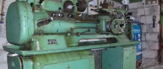
Like the 16V20 screw-cutting lathe, the 16V20P machine is produced by the Astrakhan Machine Tool Plant. This is a universal technological metal-cutting equipment used where metalworking is required. The machine is used both in mass production and in small-scale production for finishing and semi-finishing work. The 16V20P machine is distinguished from the 16V20 machine by its accuracy class. The 16V20P screw-cutting lathe belongs to the high-precision class according to GOST 8-82.
Information about the manufacturer of the screw-cutting lathe 16B20p
Manufacturer of universal lathes 16B20p - Moscow Machine Tool Plant named after. A.I. Efremova , founded in 1857.
The first universal screw-cutting lathes with a gearbox for the first time in the USSR began to be produced at the Moscow Machine Tool Building named after. A.I. Efremov in 1932 and received the names DIP-200, DIP-300, DIP-400, DIP-500 ( DIP
- Catch up and Overtake), where 200, 300, 400, 500 is the height of the centers above the frame.
As the design of the machines improved, the plant produced more and more modern models - 1A62, 1K62, 16K20, MK6056.
Machine tools produced by the Moscow Machine Tool Plant Krasny Proletary, KP
- 1A62
- universal screw-cutting lathe Ø 400 - 1K62
- universal screw-cutting lathe Ø 400 - 1K62B
- universal screw-cutting lathe with increased accuracy Ø 400 - 1K282
- eight-spindle vertical lathe Ø 250 - 1K620
- universal screw-cutting lathe with variator Ø 400 - 1K625
- lightweight screw-cutting lathe with an increased line of centers Ø 500 - 16A20F3
– CNC lathe Ø 400 - 16B20P
- high-precision screw-cutting lathe Ø 400 - 16K20
– universal screw-cutting lathe Ø 400 - 16K20M
- mechanized screw-cutting lathe Ø 400 - 16K20P
- high-precision screw-cutting lathe Ø 400 - 16K20F3
– CNC lathe Ø 400 - 16K20F3S32
– CNC lathe Ø 400 - 16K20T1
- lathe with operational control Ø 500 - 16K25
- lightweight screw-cutting lathe with an increased line of centers Ø 500 - 162
— universal screw-cutting lathe Ø 420 - 1730
— semi-automatic multi-cutting lathe Ø 410 - DIP-40 (1D64)
- universal screw-cutting lathe Ø 800 - DIP-50 (1D65)
- universal screw-cutting lathe Ø 1000 - DIP-200
– universal screw-cutting lathe Ø 400 - DIP-300
– universal screw-cutting lathe Ø 630 - DIP-400
– universal screw-cutting lathe Ø 800 - DIP-500
– universal screw-cutting lathe Ø 1000 - MK6046, MK6047, MK6048
- universal screw-cutting lathe Ø 500 - MK6056, MK6057, MK6058
- universal screw-cutting lathe Ø 500 - MK-3002
- table lathe Ø 220
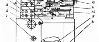
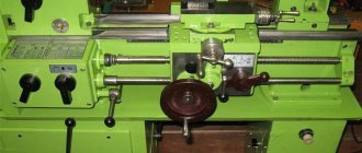
Location of controls for screw-cutting lathe 16B20P
Location of controls for screw-cutting lathe 16B20p
List of controls for screw-cutting lathe 16B20P
- Spindle speed setting handle
- Spindle speed setting handle
- Handle for setting normal and increased pitch and dividing into multi-start threads
- Handle for setting right or left thread
- Handle for selecting thread type and type of work (threading or feeding)
- Feed or thread setting handle
- Feed or thread setting handle
- Handwheel for manual longitudinal movement of the caliper carriage
- Lead screw nut on/off handle
- Longitudinal feed dial clamp handwheel
- Button for disengaging the rack and pinion gear when cutting threads
- Caliper lateral movement handle
- Button for turning on the mechanical movement of the upper support (cutting slide)
- Clamp handle against turning the lead screw to move the upper support (cutting slide)
- Upper slide (cutter slide) feed handle
- Handle for rotating, indexing and clamping the cutting head
- Handle for turning on, stopping and reversing the spindle
- Mnemonic caliper group handle
- Button for rapid movement of apron and caliper
- Tailstock quill clamp handle
- Tailstock clamp handle on bed guides
- Handwheel for moving the tailstock quill
- Lead screw activation button directly
- Power switch
- Button for turning on the electric motor at speed 1
- Button for turning on the electric motor at speed II
- Push-button station for starting and stopping the main electric motor
- Feed and thread switch
- Coolant pump switch
- Main motor ammeter
- Machine stop
- Push
- Left handle for turning on, stopping and reversing the spindle
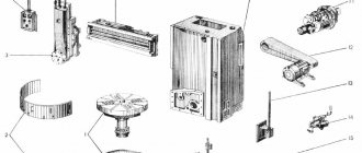
List of components of the screw-cutting lathe 16B20P
- RMC bed 1400 mm - 16B20P-010
- RMTs bed 1000 mm - 16B20P-011
- RMTs bed 710 mm - 16B20P-012
- Left leg - 16B20P-013
- Right leg - 16B20P-014
- Spindle head - 16B20P-020 (Gamet bearing supports)
- Gearbox - 16B20P-024
- Tailstock - 16B20P-030
- Caliper with mechanical feed - 16B20P-040
- Caliper without mechanical feed - 16B20P-044 (only for a machine with RMC 1400 mm)
- Tool holder - 16B20P-043
- Mechanical feed carriage - 16B20P-050
- Carriage without mechanical feed - 16B20P-051 (only for a machine with RMC 1400 mm)
- Apron - 16B20P-060
- Feed box - 16B20P-070
- Gearbox - 16B20P-080
- Setting table for replacement gears (guitar) - 16B20P-081
- Drive cartridge - 16B20P-090
- Adapter flange for three-jaw chuck Ø250 mm - 16B20P-095
- Tool
- High speed drive
- Lead screw RMC 1400 mm - 16B20P-152
- Lead screw RMC 1000 mm - 16B20P-153
- Lead screw RMC 710 mm - 16B20P-154
- Main drive pulleys - 16B20P-160 (only for a machine with RMC 710 and 1400, Nshp = 16..1600)
- Main drive pulleys - 16B20P-161 (only for a machine with RMC 1400, Nshp = 12.5..1250)
- Main drive pulleys - 16B20P-162 (only for the machine with Nshp = 20..2000)
- Main drive pulleys - 16B20P-163 (only for a machine with RMC 1000, with Nshp = 16..1600)
- Electrical equipment - 16B20P-180
- Table of speeds and feeds - 16B20P-225 (for a machine with Nshp = 16..1600)
- Table of speeds and feeds - 16B20P-226 (for a machine with RMC 1400, Nshp = 12.5..1250)
- Table of speeds and feeds - 16B20P-227 (for a machine with Nshp = 20..2000)
- Centralized lubrication - 16B20P-240
- Cooling - 16B20P-250
- Cooling - 16B20P-261
- Limbs and mechanism for disabling the front propeller handle - 16B20P-52
- Left spindle control handle - 16B20P-071
Kinematic diagram of screw-cutting lathe 16B20P
Kinematic diagram of a screw-cutting lathe 16B20p
The kinematic diagram is given to understand the connections and interactions of the main elements of the machine. The numbers of teeth (g) of the gears are indicated on the callouts (the asterisk indicates the number of starts of the worm).
The number I indicates a support with mechanical movement of the cutting slide
Movement is transmitted to the spindle in the following sequence:
- Two-speed electric motor 695 / 1400 rpm. Motor speed is selected using buttons
- Flat drive gearbox
- 6 speed gearbox
- Flat drive to spindle headstock
Setting the spindle speed in the spindle head is done by handle 1, which moves blocks 18-19-21-25-26.
Structural diagram
The passport of the screw-cutting lathe 16b20p-061 describes its design. For rigidity, the machine bed is box-shaped and mounted on a base. The frame has ground guides that are hardened. Chips accumulate in a special cavity in the base. There is also an open container for coolant.
The precision bearings on which the machine spindle rests are not adjustable. At the output end of the spindle there is a flange with a fixed 3-jaw chuck.
The input end of the spindle, through a replaceable set of gears and a drive shaft or screw, transmits rotation to the feed box. It moves the support with the tool holder during turning of workpieces or making threads.
There are scales with sights on the caliper. They facilitate visual control of the movement of the slide during the cutting process. The tool holder securely fixes four cutters.
The apron is equipped with end stops with switches for confident stopping of the caliper feed mechanism. There are other locks and cutting zone guards available to guarantee safe operation of the machine.
When using a 16b20p lathe, it is important to monitor its condition - general and main structural elements. This greatly affects the accuracy of the operations performed and the surface quality of the parts. The guides of the caliper and frame require special attention.
Electrical diagram
The electrical circuit of the 16b20p-070 lathe is necessary for correct power connection when starting up the equipment, its operation and repair.
Description of the design of the screw-cutting lathe 16B20P
bed
The machine bed is cast; a rapid-speed electric motor is installed in a niche at the right end. The bed is installed on two hollow pedestals. The left one houses the main drive electric motor, the right one houses the electric cooling pump with an emulsion tank and the electric lubrication pump with a tank.
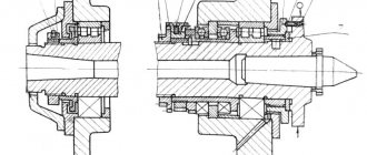
Front (spindle) headstock of screw-cutting lathe 16B20P
The position of the spindle axis relative to the frame guides is adjusted using set screws.
The spindle head contains:
- Pitch increasing link with gear ratios 1:1, 1:4, 1:16
- Spindle unit
- Gear mechanism for cutting right-hand and left-hand threads
The spindle assembly is mounted on special cone-roller bearings of the Gamet type (Gamet Bearings is an English manufacturer of precision bearings for equipment).
The gearbox for 6 spindle revolutions is removed from the spindle head and is mounted inside the left cabinet of the machine.
The gearbox contains:
- Gear mechanism (reducer)
- Starting and braking electromagnetic clutches
- Selective gearbox control mechanism
Main movement mechanism of screw-cutting lathe 16B20p
Gearbox
The feed box is mounted on the left side of the frame.
The feed box mechanism with replaceable guitar gears makes it possible to cut the entire main series of threads provided for by GOST.
Using the pitch increasing link, you can obtain threads with a pitch increased by 4 and 16 times
When specially tuning a guitar, small threads are cut in increments of 0.2 mm.
Feed selection is made by three handles mounted on the box.
- The left handle (6) selects a thread from the main row
- The right handle (7) moves the gear wheels of the multiplying mechanism
- The middle handle (5) selects the type of threads and work
An overrunning clutch is mounted on the right side of the box to obtain accelerated movements of the carriage and caliper.
Feed mechanism of screw-cutting lathe 16B20p
Setting up a 16B20p machine for cutting threads (table of threads)
Apron
The apron is equipped with four fine-toothed couplings that provide forward and reverse movement of the carriage and support in forward and reverse directions
The movements of the carriage and the lower part of the support are controlled by a mnemonic handle.
When working against stops or accidental overloads, the safety device of the apron, directly acting on the control mechanism, moves the fine-toothed clutches to the neutral position.
The ball locking device prevents the simultaneous activation of the uterine nut and longitudinal and transverse movements.
Caliper
The cross-design support has manual and mechanical longitudinal movement along the frame guides (carriage) and transverse movement along the carriage guides.
The upper support with a tool holder also has mechanical movement for turning short cones (the length of the cone generatrix is no more than 140 mm.
Specifications
Universal screw-cutting lathe for metal TV-320: description, technical characteristics, diagrams
One of the main features of the 16U04P screw-cutting lathe is stepless control of the spindle speed in forward and reverse directions, which is ensured by the use of a V-belt variator. Among the positive characteristics, the values of the maximum turning diameter and quill overhang are usually noted, and as a disadvantage, they indicate the small size of the spindle through hole. Main technical characteristics of 16U04P (linear dimensions in mm):
- height: center-to-center axis above the frame - 108, turning above the guides - 100, turning above the carriage - 59;
- center distance - 350;
- through hole in the spindle - Ø 20;
- quill stroke - 70;
- spindle speed range - 70÷3500 rpm;
- main drive power - 800 W.
- machine/stand weight - 360/390 kg;
In the 16U04P passports available for viewing, only one center-to-center distance size is indicated - 350 mm. However, it is absolutely known that the plant produced an extended modification of the lathe with an RMC of 450 mm.
Technical characteristics of the lathe 16B20P
| Parameter name | 16B20P | 16K20P |
| Basic machine parameters | ||
| Accuracy class according to GOST 8-82 | P | P |
| The largest diameter of the workpiece installed above the bed, mm | 400 | 400 |
| Height of the center axis above the flat guides of the frame, mm | 215 | 215 |
| The largest diameter of the workpiece processed above the support, mm | 220 | 220 |
| Maximum length of the part installed in the centers (RMC), mm | 1000 | 710, 1000 |
| The greatest distance from the axis of the centers to the edge of the tool holder, mm | 225 | 225 |
| The largest diameter of the drill when drilling steel parts, mm | 25 | |
| The largest mass of the part processed in the centers, kg | 460..1300 | |
| Maximum mass of the part processed in the chuck, kg | 200 | |
| Spindle | ||
| Spindle hole diameter, mm | 52 | 52 |
| The largest diameter of the rod passing through the hole in the spindle, mm | 50 | 50 |
| Spindle rotation speed in the forward direction (depending on the set of main motor pulleys), rpm | 16..1600 12,5..1250 100..2000 | 12,5..1600 |
| Spindle rotation speed in reverse direction, rpm | 19..1900 | |
| Number of forward spindle speeds | 22 | 22 |
| Number of spindle reverse speeds | 11 | |
| Spindle end according to GOST 12593-72 | 6K | 6K |
| Tapered spindle bore according to GOST 2847-67 | Morse 6 | Morse 6 |
| Spindle flange diameter, mm | 170 | 170 |
| Maximum torque on the spindle, Nm | 1000 | |
| Caliper. Submissions | ||
| Maximum length of longitudinal movement, mm | 930 | 645, 935 |
| Maximum length of transverse movement, mm | 250 | 300 |
| Speed of fast longitudinal movements, m/min | 4,0 | 3,8 |
| Speed of fast transverse movements, m/min | 2,0 | 1,9 |
| Maximum permissible speed of movement when working on stops, mm/min | 250 | |
| Minimum permissible speed of movement of the carriage (support), mm/min | 10 | |
| Price for dividing the longitudinal movement dial, mm | 1 | 1 |
| Transverse movement dial division price, mm | 0,05 | 0,05 |
| Longitudinal feed range, mm/rev | 0,05..2,8 | 0,05..2,8 |
| Transverse feed range, mm/rev | 0,025..1,4 | 0,025..1,4 |
| Number of feeds longitudinal/transverse | 22/24 | 22/24 |
| Limits of metric thread pitches, mm | 0,5..112 | 0,5..112 |
| Limits of pitches of inch threads, threads/inch | 56..0,25 | 56..0,5 |
| Limits of modular thread pitches, module | 0,5..112 | 0,5..112 |
| Limits of pitch thread pitches, diametric pitch | 56..0,25 | 56..0,5 |
| The greatest force allowed by the feed mechanism on the cutter is longitudinal, N | 5884 | |
| The greatest force allowed by the feed mechanism on the cutter is transverse, N | 3530 | |
| Cutting slide | ||
| Maximum length of movement of the cutting slide, mm | 150 | 150 |
| Movement of the cutting slide by one division of the dial, mm | 0,05 | 0,05 |
| Scale of rotation angle of the cutting slide, deg | ±90° | ±90° |
| Scale division of the tool slide rotation scale, deg | 1° | 1° |
| The largest cross-section of the cutter holder, mm | 25 x 25 | 25 x 25 |
| Height from the supporting surface of the cutter to the axis of the centers (cutter height), mm | 25 | 25 |
| Number of cutters in the cutting head | 4 | 4 |
| Tailstock | ||
| Quill diameter, mm | ||
| Tailstock quill hole cone according to GOST 2847-67 | Morse 5 | Morse 5 |
| Maximum movement of the quill, mm | 200 | 150 |
| Movement of the quill by one division of the dial, mm | 5 | 0,1 |
| The amount of lateral displacement of the headstock body, mm | ±15 | ±15 |
| Electrical equipment | ||
| Main drive electric motor, kW | 4,1/ 6,6 | 11 |
| Electric motor for fast movement drive, kW | 0,6 | 0,12 |
| Lubrication pump drive electric motor, kW | 0,27 | |
| Coolant pump electric motor, kW | 0,125 | 0,125 |
| Dimensions and weight of the machine | ||
| Machine dimensions (length width height) RMC=1000, mm | 2595 x 1405 x 1115 | 2795 x 1190 x 1500 |
| Machine weight, kg | 2050 | 3010 |
* the price of a restored machine is indicated (since these machine models are no longer produced)
Equipment Specifications
The screw cutting machine has a wide range of technical features:
- The power of the electric motor ensures the functioning of the main drive and reaches 7.5 kW. And the drive itself, responsible for moving the caliper, has a power of 0.37 kW. The electric motor for the lubrication mechanism is 0.12 kW;
- the maximum length of the workpiece to be turned is 1.46 meters, and the maximum dimensions of the product fixed at the centers of the machine are 1.5 meters;
- Automatic transmission;
- thread cutting is carried out by the worker selecting a step, which he sets based on the type of workpiece;
- the maximum cross-section of the workpiece turned above the bed should not be more than 40 centimeters, and above the support - 21 centimeters;
- the number of revolutions of the spindle device in forward motion is from 25 to 2500 rpm, and in reverse motion – from 25 to 1250 rpm;
- in forward movement, the spindle device has 21 speed levels, and in reverse – 18;
- the machine is driven by a 2-speed electric motor together with a gearbox and a bulkhead that programs 12 speed levels of the spindle mechanism in any of the 2 ranges;
- transverse feeds vary from 0.025 to 1.4 mm, and longitudinal feeds - from 0.05 to 2.8 mm per rotation;
- The range of movement of the caliper along the screw is 75 centimeters (lengthwise) and 22 centimeters (crosswise). The maximum distance of its movement along the roller is 50 centimeters;
- Rolling bearings create rigid and high-precision support;
- the guides of the carriages and the rolling pairs of the screws have impulse lubrication;
- feed drive provides stepless feed adjustment;
- loading and unloading of parts is carried out manually.
These technical parameters enable the car to enjoy popularity even 50 years from the date of its release. The letters “K” and “P” in the name of the machine indicate that there is a copying mechanism and an increased degree of accuracy, respectively. The screw cutting machine is capable of operating from a mains voltage of 220, 380, 400, 415 and 440 V. It is characterized by a modern ergonomic structure and is easy to operate and control.
Dimensions and weight of the machine
The screw cutting machine is small in size and weight for a machine with similar functionality:
- width – 1110 millimeters;
- height – 1505 millimeters;
- length – 2270 millimeters;
- weight – 2 tons.
Purpose and scope
The 16b16kp machine is intended for performing various turning operations in centers, collets or in a 3 or 4-jaw chuck, for cutting various threads with a die or tap. Unlike most other brands, such a machine is intended for more thorough turning, and therefore is not recommended for roughing. It is usually installed in small repair shops. After processing on a lathe, the products are distinguished by excellent surface cleanliness.