Information about the manufacturer of the educational screw-cutting lathe TV-6
The manufacturer of the screw-cutting lathe model TV-6 is the Rostov plant of small-sized machine tools MAGSO , founded in 1956.
ComTech Financial and Industrial Group , which has existed in the machine tool equipment market for several years and has priority in the production of small-sized metal-cutting machines: lathes, milling, vibrating, sharpening, drilling, which equip schools, vocational schools, colleges, institutes, repair and installation organizations of all regions of Russia.
Machines produced by the Rostov plant of small-sized machine tools MAGSO
- NS-16 - tabletop drilling machine Ø 16
- NGF-110Sh3 - low power milling machine 0.6 kW, table size 100x400 mm
- NGF-110Sh4 - low power milling machine 0.75 kW, table size 100x400 mm
- SNVSH - tabletop drilling machine Ø 16
- SNVSH-2 - tabletop drilling machine Ø 16
- TV-4
- educational screw-cutting lathe Ø 200, RMC 350 mm - TV-6
- educational screw-cutting lathe Ø 200, RMC 350 mm - TV-6M
- educational screw-cutting lathe Ø 200, RMC 350 mm Dubno - TV-7
- educational screw-cutting lathe Ø 220, RMC 330 mm - TV-7M - educational screw-cutting lathe Ø 220 mm, RMC 275 mm
- TV-9 - educational screw-cutting lathe Ø 220 mm, RMC 525 mm
- TV-11 - educational screw-cutting lathe with frequency converter Ø 240, RMC 750 mm
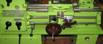
TV-6 (TV6) educational screw-cutting lathe. Purpose, scope
The TV-6 school screw-cutting lathe replaced the TV-4
and was replaced by a more advanced model
TV-6M .
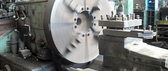
The TV-6 machine is an educational universal screw-cutting lathe and is intended for all kinds of turning work in workshops of schools for polytechnic training and cold metal cutting.
Operating principle and design features of the machine
The educational screw-cutting lathe TV-6 , despite its simplified design, has all the components of an “adult” screw-cutting lathe: gearbox, guitar, feed box, drive shaft and lead screw, caliper with mechanical feed.
The TV-6 machine has 6 spindle speeds by switching gears in the headstock box, 3 caliper feed speeds , and can cut 3 metric threads without rearranging the gears in the guitar.
The end of the spindle of the TV-6 has an M36x4 thread, therefore, to install a lathe or driving chuck on the spindle, an intermediate flange (also called a plan washer) is required (see the article Lathe chucks). The standard chuck for the TV-6 machine is Ø100 mm.
The TV-6 machine is driven by an asynchronous electric motor ~380V. Through a V-belt drive and single-stage pulleys, the movement is transmitted to the input shaft of the gearbox. Inside the gearbox, movement is transmitted through gears to the spindle. The spindle, depending on the position of the handles on the headstock, rotates at one of 6 speeds. The direction of spindle rotation is determined by the motor.
From the spindle, through the gears, the movement is transmitted to the output shaft of the gearbox, then to the guitar, and from it to the input shaft of the gearbox.
At the output of the feed box there is a lead shaft and a lead screw, which rotate alternately at one of 3 speeds. The lead screw is turned on when cutting threads. The speed and direction of rotation of the lead screw is set by the handles on the feed box and determines one of 3 metric threads (the lead screw can be used in longitudinal feed mode, but is not used so as not to wear it out), the lead shaft makes it possible to obtain one of 3 longitudinal feeds of the caliper. The feed speed and direction are set by the handles on the front wall of the feed box.
The lead screw and lead shaft pass through the caliper apron, which converts the rotational movement of the lead screw or lead shaft into forward longitudinal movement of the caliper. Transverse mechanical movement of the support in the TV-6 machine is not provided.
Gearbox lubrication by spraying oil from the oil bath at the bottom of the headstock onto the gears. The feed box is lubricated with a wick from a tray, which is filled with oil once per shift. The apron, caliper, guitar, tailstock and bed are lubricated by hand once per shift.
The machine allows you to perform the following types of turning work:
- Grooving and boring of cylindrical and conical surfaces
- End trimming
- segment
- Metric thread cutting
- Drilling and a number of other works
Design
TV 6 lathe includes the following parts:
- mode control unit;
- cabinets located in front and behind;
- screen for protection;
- trough for the supply of lubricating fluid;
- front and rear stock;
- machine apron;
- supporting frame;
- electrical components;
- guitar;
- protective casing.
The mode control unit is driven by gears of the transmission unit and contains:
- 2 shafts;
- 5 gears with different characteristics;
- block gears;
- travel roller;
- couplings;
- a circle-shaped nut;
- switch handle;
- drain cover.
The handle on the front side of the adjustment unit makes it possible to set the indicators of the thread created on the part.
The handle, which is located on the feed unit panel, allows you to turn on the drive roller. It is not possible to turn on the screw and the drive shaft at the same time. A similar limitation is present in machines used in production. Lubrication of all parts of the feed box (gears, contacting parts) is carried out thanks to the oil fluid, which is supplied from the trough through special wicks.
The cabinet located at the front is shaped like the letter “P”. Its rigidity is enhanced by special ribs located at the top and bottom. The electric drive of the machine is mounted at the back, and at the front there is a button that controls the reverse activation. A similar device has a cabinet located at the back. A panel with electrical equipment is installed on it.
The tailstock, which has a Morse taper mounting hole, contains:
- main part;
- hub body;
- connecting screws;
- quill;
- key screw;
- a flywheel that controls the movement of the quill;
- handles for securing the quill and tailstock.
The tailstock makes it possible to move the quill by 6.5 cm.
The supporting frame of the machine, through which all parts of the structure are combined and maintain their original location, has a box-like appearance and has several windows. There are 2 guide prisms on it. The frame itself is supported by a pair of pedestals.
One of the most important parts of the TV 6 machine is the apron, consisting of:
- 4 gears (2 worm and rack each);
- control handles;
- flywheel controlling manual feed;
- uterine nut;
- a stroke roller designed for longitudinal feed of the support element;
- shaft
The support element of the TV 6M machine includes 4 carriages. This part of the device is intended to fix the cutter and move it when processing the part. The cutter holder in which the tool is secured is located on the fourth carriage. It can move longitudinally along the guides of the third carriage. The 3rd carriage, fixed to the second, is considered to be rotating, and the second is fixed to the first, moving transversely.
To transfer torque from the gearbox to the feed box, a special unit called a guitar is used. The main part of the guitar is the bracket with the gears installed. Gears cannot be changed; therefore, the gear index provided by the guitar is considered constant and equal to one fourth.
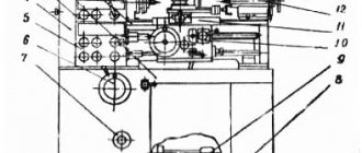
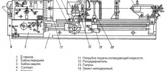
Location of the components of the TV6 screw-cutting lathe
Location of the components of the TV6 screw-cutting lathe
Specification of components of the TV6 screw-cutting lathe
- Handle for switching the speed of rotation of the drive shaft and lead screw
- Handle for switching the speed of rotation of the drive shaft and lead screw
- Guitar gear shift knob
- Spindle speed switch handles
- Spindle speed switch handles
- Caliper cross feed handle
- Tool holder fastening handle
- Upper slide handle
- Quill mounting handle
- Tailstock mounting handle
- Quill feed flywheel
- Mechanical feed control handles
- Mechanical feed control handles
- Button
- Caliper movement flywheel
- Buttons to turn the motor on and off
Location of controls for the TV-6 screw-cutting lathe
Location of controls for the TV-6 screw-cutting lathe
Specification of controls for the TV-6 screw-cutting lathe
- Spindle speed setting knobs
- Spindle speed setting knobs
- Handle for setting the cutting of right and left threads and changing the direction of feeds
- Handle for setting the feed rate and thread pitch
- Drive roller shift handle
- Reversible button to start and stop the machine
- Guard to the cartridge
- Protective screen
- Cutting head mounting handle
- Local lighting lamp K-1M
- Handle for manual movement of the cross slide
- Handle for moving the upper (incisor) slide
- Tailstock quill fastening handle
- Handle for attaching the tailstock to the bed guides
- Tailstock quill movement flywheel
- Rack and pinion on/off button
- Flywheel for manual movement of the longitudinal carriage
- Lead screw nut engagement handle
- Mechanical feed limit handle
- Shield guard for lead screw and shaft
- Transformer OSZR-0.063-83UHL3 TU 16-671.041-84
Table of controls for the TV-6 screw-cutting lathe
Table of symbols for the TV-6 screw-cutting lathe
TV-6 machine control
Starting and stopping the machine’s electric motor is done by pressing the “Start” and “Stop” buttons.
Depending on the nature of the work on the machine, the handles and control levers must be in certain positions (see Fig. 3).
I. Position of handles and levers when working on thread cutting (mechanical feed by lead screw)
- On the headstock - the position of the bit handle 3 depending on the direction of feed of the caliper - left or right.
- On the feed box - the position of the feed box lever 4 depending on the selected feed amount. Lever 5: “Screw-shaft” in the right “Screw” position.
- On the apron is the handle of the self-propelled gun 8 in the lower off position “Push away”.
- The rack and pinion gear lever 7 is in the “Pull” position.
- The handle for turning on the uterine nut 9 is in the lower extreme position.
II. Position of handles and levers when working with the drive shaft (mechanical feed)
- On the headstock - the position of the bit handle 3 depending on the direction of feed of the caliper (left or right).
- On the feed box - the position of the feed box lever 4 depending on the selected feed amount. Lever 5 “Shaft-screw” - in the left extreme position “Shaft”.
- On the apron is the self-propelled handle 8 in the “Pull” position.
- The handle for turning on the uterine nut 9 is in the upper position.
- The rack and pinion gear lever 7 is in the “Push away” position.
III. Position of handles and levers for manual longitudinal feed
- On the headstock - the position of the bit handle 3 is in the middle position.
- On the feed box, the position of the “Shaft-screw” lever is indifferent.
- On the apron is the self-propelled handle in the off position. The lever of the uterine nut is in the upper position.
IV. The position of the control handles to obtain the required cutting conditions according to Fig. 14
Basic functions of elements
A basic lathe consists of a bed (base) and its guides, a main drive (motor), a support and an apron, a headstock and a tailstock, a pallet, and a feed box.
Features of headstocks
The headstock is necessary to securely fasten the part, as well as supply torque to the workpiece. The part is held in the chuck using a clamp with a special key. This element is located on the left side of the frame and has gears that provide a rotational function. They are also able to change the speed mode thanks to three switches located on the front of the headstock.
The tailstock of a screw-cutting lathe works simultaneously with the front one, but is located on the right side of the base. This element has the same functions, but it does not have complex mechanisms of gears and other things. In this case, it can move along the frame guides in the axial direction.
The tailstock ensures reliable holding of the workpiece in a vertical position. If it is removed from the configuration, the workpiece will experience precession during rotation, which guarantees its instability. It is worth noting that for drilling work, the headstock is an element for feeding the part onto the drill.
Structure of the bed and feed box
For a lathe model TV-6, as for any turning-milling or screw-cutting units, the bed serves as the supporting part or base for all the main elements of the mechanism. However, it must meet certain parameters. Its dimensions are quite compact, and the maximum weight it can withstand is 600 kg, while the weight of the machine itself is only 300 kg.
The functionality of the feed box is to timely switch the speed of the screw and shaft. To carry out such a procedure, there are 2 levers that relate to each element respectively. It also provides access to the gears for lubrication.
Functions of the caliper and its apron
The support apron is one of the main mechanisms of a lathe. With its help, the supply of the cutting tool is ensured. It is based on an element that moves perpendicular to the axis of the workpiece being processed. Additionally, it is equipped with a caliper and apron movement control handles. In practice, the work is as follows:
- using levers on the apron, the cutter is fed to the body of the blank;
- the apron moves parallel to the workpiece axis along the bed guides, removing the required layer of material.
The support in the TV-6 screw-cutting lathe is a kind of cutter holder and allows you to feed the cutting edge perpendicular to the center of the part. It is worth noting that this element operates continuously throughout the entire turning process. If the caliper is in a faulty condition, this significantly reduces the quality of processing. To extend its service life, it is necessary to tighten all bolts tightly, eliminating the occurrence of vibration.
Requirements for guides, motor and pallet
The bed skids are rails along which the support mechanism and tailstock of a TV6 type lathe move. Moreover, the smoother they are, the higher the quality of work. It is worth noting that throughout the entire period of operation of this equipment, there were no cases of malfunction of the guides, since they have a long service life.
The pallet looks like a tabletop, which is located between the bed and the main elements of the machine. It plays the role of a collector of lubricants that enter it during operation. The electric motor is located between the frame and the pallet and is the main element that drives all mechanisms using a belt drive.
In order for the work to be carried out as efficiently as possible, it is necessary to monitor the serviceability of all mechanisms. Lubricate the components and clean the lathe in a timely manner. You must also follow the rules for operating electrical appliances.
Kinematic diagram of the TV-6 screw-cutting lathe
Mechanisms of the TV-6 screw-cutting lathe
Kinematic diagram of the TV-6 screw-cutting lathe
List of bearings for the TV-6 screw-cutting lathe
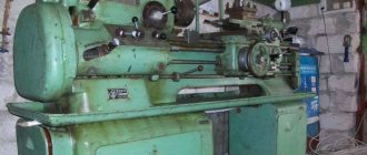
Tabletop lathe TV-9 - technical specifications, passport
Screw-cutting lathes are the basis of modern machining. They make it possible to obtain bodies of revolution of various shapes, with holes, grooves, and recesses. Even small and not the most complex equipment has impressive functionality.
Compared to modern machining turning centers, universal machines have lower productivity, but the accuracy and level of complexity of the work are quite comparable. In this case, the cost will be an order of magnitude less. They are suitable for repair, one-off, small-scale and medium-scale production.
Technical characteristics of the TV-6 machine
| Parameter name | TV-4 | TV-6 | TV-7 |
| Basic machine parameters | |||
| Accuracy class | N | N | N |
| The largest diameter of the workpiece above the bed, mm | 200 | 200 | 220 |
| The largest diameter of the workpiece above the support, mm | 125 | 80 | 100 |
| Height of centers above flat bed guides, mm | 108 | 108 | 120 |
| Maximum length of the workpiece at centers (RMC), mm | 350 | 350 | 330 |
| Maximum length of the workpiece in the chuck, mm | 310 | ||
| Maximum turning length, mm | 300 | 300 | 300 |
| Maximum height of the cutter holder, mm | 10 x 12 | 12 x 12 | 16 x 16 |
| Height from the cutting surface to the center line, mm | 12 | 12 | |
| The greatest distance from the axis of the centers to the edge of the tool holder, mm | 78 | 78 | |
| Spindle | |||
| Threaded end of spindle, mm | M36 x 4 | M36 x 4 | M45 x 4 |
| Diameter of standard cartridge, mm | 100 | 100 | 125 |
| Diameter of through hole in spindle, mm | 16 | 18 | |
| Maximum rod diameter, mm | 15 | 12 | |
| Morse taper spindle | №2 | №3 | №3 |
| Number of speed steps for direct spindle rotation | 6 | 6 | 8 |
| Spindle direct rotation frequency, rpm | 120, 160, 230, 375, 500, 710 | 130, 170, 235, 385, 510, 700 | 60..1000 |
| Number of spindle reverse rotation frequency steps | 6 | 6 | 8 |
| Spindle reverse rotation frequency, rpm | 120, 160, 230, 375, 500, 710 | 130, 170, 235, 385, 510, 700 | 60..1000 |
| Spindle braking | No | No | No |
| Handle lock | No | No | No |
| Caliper. Submissions | |||
| Maximum longitudinal movement of the caliper, mm | 300 | 300 | 260 |
| Longitudinal movement of the caliper by one dial division, mm | 0,5 | 0,25 | 0,25 |
| Maximum lateral movement of the caliper, mm | 100 | 100 | |
| Transverse movement of the caliper by one division of the dial, mm | 0,025 | 0,025 | 0,025 |
| Maximum movement of the cutting slide, mm | 50 | 85 | 85 |
| Movement of the cutting slide by one division of the dial, mm | 0,025 | 0,025 | 0,025 |
| Angle of rotation of the cutting slide, degrees | ±45° | ±40° | ±40° |
| Number of stages of longitudinal feed of the caliper | 3 | 3 | 8 |
| Limits of longitudinal working feeds of the caliper, mm/rev | 0,08; 0,1; 0,12 | 0,08; 0,1; 0,12 | 0,1; 0,12; 0,15; 0,16; 0,18; 0,20; 0,24; 0,32 |
| Limits of working cross feeds of the caliper, mm/rev | No | No | No |
| Number of metric threads to be cut | 3 | 3 | 6 |
| Limits of pitches of cut metric threads, mm | 0,8; 1,0; 1,25 | 0,8; 1,0; 1,25 | 0,8; 1,0; 1,25; 1,5; 2,0; 2,5 |
| Limits of pitches of cut inch threads | No | No | No |
| Limits of pitches of cut modular threads | No | No | No |
| Limits of pitches of cut pitch threads | No | No | No |
| Tailstock | |||
| Morse taper tailstock | №2 | №2 | №2 |
| Maximum movement of the quill, mm | 65 | 65 | 65 |
| Electrical equipment | |||
| Main drive electric motor, kW | 1,0 | 1,1 | 1,1 |
| Dimensions and weight of the machine | |||
| Machine dimensions (length width height), mm | 1440 x 470 x 1020 | 1100 x 470 x 110 | 1050 x 535 x 1200 |
| Machine weight, kg | 280 | 300 | 400 |
- Screw-cutting lathe (training) TV-6. Passport, 1983
- TU 79 RSFSR 507-80
- Acherkan N.S. Metal-cutting machines, Volume 1, 1965
- Batov V.P. Lathes, 1978
- Beletsky D.G. Handbook of a universal turner, 1987
- Denezhny P.M., Stiskin G.M., Thor I.E. Turning, 1972. (1k62)
- Denezhny P.M., Stiskin G.M., Thor I.E. Turning, 1979. (16k20)
- Lokteva S.E. Computer controlled machines, 1986
- Modzelevsky A. A., et al. Lathes, 1973
- Pikus M.Yu. A mechanic's guide to machine repair, 1987
- Skhirtladze A.G., Novikov V.Yu. Technological equipment for machine-building industries, 1980
- Tepinkichiev V.K. Metal cutting machines, 1973
- Chernov N.N. Metal cutting machines, 1988
Bibliography:
Related Links. Additional Information
- Classification and main characteristics of turning
- Selecting the right metalworking machine
- Multi-start thread. Methods for cutting multi-start threads on a lathe
- Graphic signs for lathes
- Friction clutch of a screw-cutting lathe
- Lathe repair technology. Repair of bed and support guides
- Lathe repair technology. Repair of headstock and tailstock
- Lathe spindle repair
- Methodology for checking and testing screw-cutting lathes for accuracy
- Directory of lathes
- Manufacturers of lathes
Home About the company News Articles Price list Contacts Reference information Interesting video KPO woodworking machines Manufacturers
Table-top screw-cutting lathe TV-9
TV-9 universal screw-cutting lathe is designed to perform all types of turning operations on centers, in a chuck, in a collet, and for cutting threads. The machine corresponds to accuracy class N.
The machine allows you to confidently process parts weighing up to 10 kg and a length of up to 500 mm. In this case, metal removal in one pass can be up to 4 mm per diameter. The weight of the machine allows installation on a stand, workbench, or desktop.
The improved characteristics of the TV-9 model have expanded the scope of application of the machine. In addition to educational institutions, it is readily purchased by enterprises of the Ministry of Defense of the Russian Federation, specializing in the production of mobile repair shops.
The machine performs all types of turning operations:
TECHNICAL CHARACTERISTICS OF THE TV9 MACHINE:
| The largest diameter of the workpiece, set: | |
| - above the bed, mm - above the support, mm | 220100 |
| Maximum length of the workpiece, mm | 510 |
| Center height, mm | 120 |
| Diameter of through hole in spindle, mm | 18 |
| Pitch value of processed metric threads, mm | 0,8 — 2,5 |
| Spindle speed limits, rpm. | 60/105/185/315/555/975 |
| Electric motor, kW/V | 1,1 /380 |
| The value of the longitudinal working feeds of the caliper, mm/rev. | 0,04 — 0,31 |
| Spindle radial runout (for class H), µm | 10 |
| Axial runout of the spindle (for class H), µm | 10 |
| Tolerance of coolness of the processed product (for class H), µm | 16 |
| Overall dimensions of the machine, mm, no more | 1350x620x680 |
| Machine weight, kg, no more | 230 ± 5% |