Information about the manufacturer of the screw-cutting lathe 1E61M
Manufacturer of the high-precision screw-cutting lathe 1E61M - Ulyanovsk Machine-Building Plant named after. Volodarsky is a multidisciplinary enterprise that produced cartridges for rifled small arms, automobile spark plugs, screw-cutting machines, lifting equipment, automatic rotary lines, contactless starters, saw chains, traction, drive, roller chains, spare parts for agricultural machinery and consumer goods.
The plant produced universal screw-cutting lathes of the following models: TV-01, TV-01M, 1E61, 1E61M, 1E61MT, 1E61VM, 1E61PM, S1E61VM, S1E61PM, UT16VM, UT16PM, UT16VMT, UT16PMT, UT-320.
Machine tools produced by the Ulyanovsk Machine-Building Plant named after. Volodarsky
- 1E61
- universal screw-cutting lathe with increased precision Ø 320 x 750 - 1E61M
- universal screw-cutting lathe with increased precision Ø 320 x 710 - 1E61MT
- universal high-precision screw-cutting lathe Ø 320 x 710 - 1E61PM, 1E61VM
- universal screw-cutting lathe with increased accuracy Ø 320 x 710 - S1E61PM, S1E61VM
- universal screw-cutting lathe with increased precision, specialized Ø 320 x 710 - UT16PM
- universal screw-cutting lathe with increased precision Ø 320 x 710
1E61M Purpose and scope of screw-cutting lathe
Lathes models 1E61M are created on the basis of the TV-01M machine and belong to the class of light lathes. The beginning of serial production of the 1e61 machine was in 1965. Production of the next model 1E61PM, 1E61VM began in 1975.
The screw-cutting lathe model 1E61M is universal and is designed to perform finishing operations when turning high-precision parts and cutting various threads. Machine accuracy class - P.
Smooth cylindrical surfaces are ground when securing the workpieces in a three-jaw chuck with a through cutter.
Cylindrical boring is the cutting of a pre-drilled or unmachined hole with a boring tool.
Trimming, grooving and cutting are carried out to give the workpiece a certain Shape, size and roughness.
External grooves are machined with slotted cutters. Cutting is carried out using cutting tools.
Machining of external conical surfaces, depending on the length of the conical part and the angle of inclination of the conical surface, can be turned with a wide cutter, turning the slide of the upper longitudinal support, transverse displacement of the tailstock body using a copy-cone ruler.
Hole processing . On a lathe you can drill and process holes (drill, ream, countersink, perform cylindrical and conical boring).
Description of the design of a screw-cutting lathe
1E61M machine is driven by an individual electric motor with a power of 4.5 kW and a speed of 1335 revolutions per minute.
The movement is transmitted to the receiving pulley of the gearbox by a V-belt drive. From the gearbox, six V-belts transmit the movement further to the headstock pulley, and then, using a toothed coupling, to the spindle.
High precision threading is provided by the ability to connect the lead screw directly to the corresponding set of replacement gears on the guitar, bypassing the entire feed chain.
1E61M machine also allows you to cut threads of normal accuracy using a feed box.
The feed chain of the machine has a step increasing link , through which an eightfold increase in the table value of feeds and thread pitches is achieved.
By turning on the step increasing link, you can cut steep threads, cut all kinds of steep spirals, cut multi-start worms and perform a number of special jobs.
The machine apron has a “falling” worm mechanism that automatically turns off longitudinal and transverse feeds when working with fixed stops. At the same time, this mechanism protects the machine from damage due to overload. But when working with a lead screw, it is unacceptable to use a longitudinal stop.
In the middle part of the spindle head there is a wedge drive pulley mounted on two ball bearings. Thus, the spindle is relieved from the tension of the V-belts.
The headstock is automatically lubricated by a separate oil pump. The switching on of the main electric motor and the switching on of the oil pump are interlocked, which eliminates the possibility of the spindle head operating without lubrication.
The supply of cutting fluid to the cutting zone is carried out by an electric pump, which is turned on as needed from a separate switch.
Reversing the main movement of the machine is electrical. The spindle rotation is braked by countercurrent in the electric motor.
The high-slip electric motor used on the machine ensures an increase in the reversing frequency when cutting threads.
The production capabilities of the machine are significantly expanded with the help of a number of additional accessories included with the machine upon special order at an additional cost.
1E61M machine provides high accuracy subject to the following points:
- Do not install the machine near impact machines or machines that cause external vibrations.
- The machine should be installed in a clean, bright room, but at the same time it should be protected from direct sunlight.
- Do not install the machine near heating appliances.
- The room temperature should be maintained within 18-20° C.
Modifications of a screw-cutting lathe of the Ulyanovsk Machine-Building Plant named after. Volodarsky
- TV-01 - 1949, the first model of a series of screw-cutting lathes Ø 340 x 1000 mm
- TV-01M - screw-cutting lathe
- 1E61
- 1955, high-precision screw-cutting lathe, Ø 320 x 750 mm - 1E61M
- 1965, high-precision screw-cutting lathe, Ø 320 x 710 - 1E61MT
- high-precision screw-cutting lathe, Ø 320 x 710 - 1E61MTS - specialized high-precision screw-cutting lathe
- 1E61PM, 1E61VM
- 1975, high-precision screw-cutting lathe, Ø 320 x 710 - 1E61PMa - high-precision screw-cutting lathe, used main drive, Ø 320 x 710
- 1E61PMF3 - high-precision screw-cutting lathe with CNC “FS-2K”, Ø 250 x 630
- S1E61PM, S1E61VM
- specialized high-precision screw-cutting lathe, Ø 320 x 710 - UT16P, UT16V - 1982, high-precision screw-cutting lathe, Ø 320 x 710 mm
- UT16PM, UT16VM
- 1987, high-precision screw-cutting lathe, Ø 320 x 750 mm - UT16PMT, UT16VMT
- 1987, high-precision screw-cutting lathe, used main drive - UT16F3 - 1983, CNC screw-cutting lathe "Luch-2T", Ø 200 x 630 mm
- UT16D - high-precision screw-cutting lathe
B/s main drive - stepless spindle drive on a DC motor or thyristor frequency converter.
Model modifications
The standard model 1E61M was modernized and released in several variations. Each modification of the machine has its own characteristics in terms of operations and quality of work.
1E61M
The addition of the "M" symbol means that the machine has increased accuracy. This modification is used for roughing and finishing machining of workpieces.
1E61MT
This is a high-precision unit that is used exclusively for finishing operations.
1E61MS
Another modification of the standard equipment 1 E61M. It is also used for finishing blanks and for thread cutting.
Dimensions of the working space and connecting bases of the 1E61M screw-cutting lathe
Dimensions of the working space of the lathe 1e61m
Dimensions of the working space of the lathe 1e61m
Screw-cutting lathe bed 1e61m
Rules for setting up equipment and operation, passport
Stable operation of the machine depends on the accuracy of the preliminary settings. For a rigid type of cross-slide connection, you will need to adjust the slide wedge. The action algorithm is as follows:
- Loosen the screw a little.
- Tighten the wedge with another screw so that the movement of the slide remains smooth.
- Tighten the first screw as far as possible.
Be sure to periodically check the tension of the V-belts. They stretch out over time and this affects the safety of the turning mechanism.
The lathe's passport can be downloaded for free from the link - Screw-cutting lathe lathe 1E61M passport
Algorithm for adjusting V-belts:
- remove the front cabinet from all covers;
- tighten the slide using a special technique, running a special screw along the grooves to select the optimal tension level;
- secure the result with nuts.
Then you should adjust the spindle belts of the turning equipment.
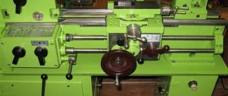
1E61M General view of the universal screw-cutting lathe model
Photo of screw-cutting lathe 1e61m
Photo of screw-cutting lathe 1e61m
Photo of screw-cutting lathe 1e61m
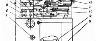
1E61M Location of the main components and controls of the machine
Location of machine controls 1e61m
List of controls for the 1E61M lathe
- Turning on the electric oil pump and connecting to an external power supply
- Switching on the emulsion electric pump
- Stop for starting, stopping and reversing the spindle
- Stop for starting, stopping and reversing the spindle
- Switching spindle speeds
- Enabling headstock override
- Snaffle and mechanism for eightfold increase in thread pitches
- Shifting Norton Cone Gears
- Inclusion of metric and modular, imperial and pitch or precision threads
- Multiplying mechanism for feeds or thread pitches
- Turning on the lead screw or lead shaft
- Handwheel for manual longitudinal movement of the carriage
- Moving the cross slide
- Moving the upper caliper slide
- Fastening the cutting head
- Enabling longitudinal or transverse feeds
- Engaging the lead screw nut
- Turning on and off the falling worm
- Attaching the support carriage to the frame
- Attaching the tailstock to the frame
- Moving the tailstock quill
- Tailstock quill fastening
- Transverse displacement of the tailstock housing
- Automatic stop for longitudinal feed
- Automatic cross feed stop
- Rigid fixation of the lead screw nut
- Turning on local lighting
- Quick removal of the cutter from the workpiece
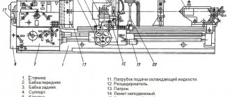
The main components of a lathe and their purpose
The source of movement in the machine is an electric motor, which transmits rotation to the spindle through a gearbox (gearbox), and from the spindle through a set of replaceable gears and a feedbox, rotation is transmitted to the lead screw m (for thread cutting) or to the run shaft N (for other turning operations). operations).
Spindle braking is carried out countercurrently.
The short workpieces are clamped in the jaw chuck, and the right end of the long workpiece is supported by a center located in the tailstock quill.
The tailstock is also used to secure and feed drills and other axial tools.
The support serves to carry out movements of the cutter fixed in the tool holder in the longitudinal and transverse directions.
The apron mechanism converts the rotational movement of the lead shaft or lead screw into the translational movement of the caliper.
Description of design
Here the user must take into account some nuances.
Location of main components
- The main unit is the bed.
Compared to other components, it has minimal weight. The part is mounted on a special platform using appropriate bolts. The bed has two guides. One of them is made in the shape of a “dovetail”, and the second looks like a prism. The support on the frame is held rigidly thanks to such shapes and wedges responsible for adjustment.
- The headstock is usually located on the left.
It is installed inside the grooves in such a way that the user can easily rotate the part a few degrees when the need arises. That is, the center moves relative to the axis without any problems. Then, when processing parts, it is easy to achieve a certain shape.
- The headstock houses the gearbox.
The control levers are located outside. A guitar of replacement gears is mounted in the front. Before cutting the thread, the gears are changed if necessary. The gearbox is the place where you can find the spindle assembly. The spindle itself rotates while maintaining speeds of up to 16-2000 rpm.
The main drive motor of the machine is located in a special cabinet on the left side. Forward and reverse rotation of the spindle is activated at any convenient moment.
- The tailstock is on the right side of the bed.
Various tools are inserted into this part, including the center and dies, taps, and drills.
The tailstock is securely fastened and moves easily along the surface of the bed. The quill stroke is 100 mm.
- An apron through which the shaft and screw pass.
- Caliper.
- Gearbox.
- Electrical cabinet.
- Lubricant and cooling fluid.
- Screen for added protection.
Headstock
The gearbox is involved in the process of transmitting the rotational motion of the spindle pulley. An individual electric motor also takes part here. Type “B” belts ensure the operation of the V-belt drive. The movement goes directly to the spindle through the bust, or bypassing it.
The design contains two rolling bearings. Due to this, the centering property is maintained, the wedge-shaped pulley of the wire does not lose its original position. The orientation is based on the central part of the spindle head. The tension of the V-belts does not have a negative effect on the structure. The spindle does not experience increased loads.
The spindle head has six speed stages in total. The block gears move along splines, which allows you to control the speed and select a specific option.
A separate pump, driven by an electric motor, is responsible for lubricating the headstock. Thanks to the presence of a lock, there is no chance that the system will start in the absence of the appropriate fluid.
1E61M Kinematic diagram of a screw-cutting lathe
Kinematic diagram of a screw-cutting lathe 1e61m
Working movements in the machine
When processing workpieces on the machine, two working movements are carried out:
- the main movement is the rotation of the spindle along with the workpiece
- feed movement:
- longitudinal feed of the cutter fixed in the tool holder support
- cross feed of cutter
- longitudinal (axial) feed of a drill, countersink or reamer fixed in the tailstock quill.
The spindle rotates by an electric motor (M) through a gearbox (P) with 6 speed levels, then through a V-belt drive to the spindle pulley and then through the headstock gears or, bypassing the drive, directly to the spindle.
Changes in spindle rotation speeds are achieved by moving gear blocks 7-8, 9-10, 11-12 of the gearbox along the splined shaft P and switching gears 52-53 of the headstock.
In Fig. Figure 2.3 shows a diagram of the feed movement drive, which is designed to transmit movement from the spindle to the support, as well as to select the feed amount and change its direction.
The feed movement is communicated from the final link of the main movement drive - the spindle - using the gear wheel 57 of the reversing mechanism.
The feed movement drive of the machine (Fig. 2.3) consists of a reversing mechanism, a set of interchangeable gears (C), a feed box (b) with a lead screw (M) and a lead roller (H) and an apron (K).
Longitudinal and transverse movements of the caliper during turning are carried out mechanically using the running roller XI through the mechanism of the feed box and apron or using a lead screw (L) and a split nut.
Manual longitudinal movement of the caliper is carried out by the handwheel (12) through gears 74-75-65 (Fig. 2.2, 2.3).
Transverse movement of the caliper by hand is carried out through screw 85 and nut 86 using handle 13.
The reversing mechanism is designed to change the direction of movement of the lead screw or lead roller, ensuring that the support with the cutter moves from right to left or from left to right.
The feed box , located on the front side of the machine, allows you to quickly change the feed amount by switching the handles.
Design of these models
The layout of the S1E61PM and 1T61M machines is similar to those of the equipment of the screw-cutting turning group. Its features include the following points:
- Bed. A rigid base is used to accurately position all nodes relative to each other. Quite a lot of attention is paid to the accuracy of the positioning of all elements.
- Headstock. To transmit rotation, a pulley is installed connected to the spindle. The main rotation is created by an individual electric motor. It was decided to eliminate the possibility of engine overheating in case of jamming of the mechanism using a V-belt drive. It is also used to change the number of revolutions. The spindle head is characterized by the presence of six gear shift speeds. In this case, the adjustment occurs due to the movement of the gear block. The presence of a large number of rubbing elements determines that a lubricant supply pump is installed to reduce wear. It also operates from the main drive.
- Caliper. Longitudinal and transverse movement of the caliper is carried out mechanically. To do this, a gearbox and an apron with a roller were installed. If necessary, a manual drive, represented by gears and a flywheel, can be used. There is also a quick feed, which is needed to change the position of the caliper.
- Tailstock. It is used to significantly improve cutting accuracy. When installing the required equipment, you can fix the workpiece at the second end, thereby reducing vibration.
- Sleds for moving moving elements. They are manufactured using stainless steel with high strength and reliability. In order for the movement of the main elements to occur without resistance, lubricating fluid is supplied to the slide.
- The control units are represented by various handles and keys, as well as dials.
Stainless steel and cast iron are used in production. The screw-cutting lathe 1E61 has a standard layout, the use of high-quality materials and the precise positioning of all elements has increased the cutting accuracy. The guitar's gears are hidden in the headstock. In addition, the 1E61M screw-cutting lathe has built-in overload protection, which significantly extends the service life of the equipment. The following technical parameters of the 1E61M model must be taken into account:
- Moving the caliper.
- Dimensions.
- Application area.
- Possible operating modes.
Download the passport (operating instructions) of the 1E61VM lathe
The technical characteristics of the models under consideration are practically the same. By taking into account the basic parameters, it is possible to determine what type of processing can be carried out.
1E61M Location of feed box control handles
Location of the feed box control handles of the machine 1e61m
Purpose of the control handles of the feed box of the 1E61M lathe
- Norton cone handle
- Guitar
- Headstock
- Inch and pitch threads
- Metric and modular threads
- Precise threads
- Multiplier feed handle
- Roller
- Lead screw
- Shift knob
- Tuning knob
1E61M Headstock of screw-cutting lathe
Headstock of screw-cutting lathe 1e61m
Spindle bearings
The spindle of the 1e61m screw-cutting lathe is mounted on 3 bearings:
- 5. Front bearing No. 4-3182114 double-row radial roller bearing, 70x110x30
- 2. Bearing No. 5-8110 single thrust ball, 55x78x16
- 1. Rear bearing No. 4-46209E single-row angular contact ball, 45x85x19
Technical characteristics of bearing No. 3182114
Bearing 3182114 is a double row radial roller bearing, with short cylindrical rollers, with a flangeless outer ring (as a result of which the set of rolling elements on the cage is able to move and create a “floating” support), with a tapered seat bore (1:12), groove and holes for adding lubricant.
The main place of operation of such bearings is machines for various applications, units where high radial loads and speeds are applied. This standard size, like most roller bearings in this series, is currently produced only with high precision. The bearing has always been produced at Moscow GPZ-1, but now its production is transferred to Volzhsky, to a branch of the Aviation Bearing Plant at 15 GPZ (all plants are united under the auspices of the European Bearing Corporation). Currently, modification 4-3182114K is being manufactured. Previously, there were much more of them. The letter K means the presence of an annular groove and three holes for introducing lubricant, E - a polyamide separator. You can buy new bearings with a quality guarantee only from official representatives of the EPK (approximate price is about 4800 rubles), but in companies dealing with illiquid assets you can buy cheaper modifications that are no longer produced, however, since these bearings for the most part, highly accurate, you need to be sure that the product was simply stored in a warehouse for a long time, and was not cleaned of rust or was in use.
Imported bearings of this size are designated NN3014K (the presence of the letter K in the number is mandatory, as it indicates a tapered fit). Products of different price categories are supplied to Russia: the most expensive and reliable are FAG, SKF, IBC, the cheaper ones are NACHI. An even cheaper option is products from Eastern European manufacturers - ZKL (Czech Republic) and FLT (Poland), which are most often sold of illiquid quality, sometimes even used, produced in the 80s of the last century. The approximate price of the highest quality and most expensive imported bearings of this type is about 300 - 305 euros (a budget option, for example, NACHI - up to 150 euros when purchased directly), they are in the warehouses of companies located in Moscow, St. Petersburg and some other large cities and are supplied to order.
Dimensions and characteristics of bearing 3182114 (NN3014K)
- Inner diameter (d): – 70 mm;
- Outer diameter (D): – 110 mm;
- Width (H): – 30 mm;
- Weight: – 1.06 kg;
- Roller dimensions: - 9x9 mm;
- Number of rollers: - 50 pcs;
- Dynamic load capacity: - 99.5 kN;
- Static load capacity: - 150 kN;
- Maximum rated speed: - 8000 rpm.
Bearing diagram 3182114 (NN3014K) lathe 1e61m
Photo of bearing 3182114 (NN3014K)
Technical characteristics of bearing No. 8110
Bearing 8110 is a single thrust ball bearing used in units with axial loads and low speeds.
During installation, it should be taken into account that one of the rings that fits onto the shaft has a diameter 1 millimeter smaller than the one that goes into the housing. Misalignment of seats must not be allowed! In the Russian Federation they are produced at SPZ-4 (Samara) and GPZ-2 (Moscow), another plant, Kursk, no longer produces them. A different marking most likely means that the bearing is made in China and there is no guarantee of quality.
Bearing 8110 is used in various centrifuges, gearboxes, supports, jacks and other mechanisms. Installed in the following components of vehicles common in our country:
Imported bearings (as well as Chinese and GPZ-2) are designated 51110.
Dimensions and characteristics of bearing 8110 (51110)
- Inner diameter (d): – 50 mm;
- Outer diameter (D): – 70 mm;
- Width (H): – 14 mm;
- Weight: – 0.162 kg;
- Ball diameter: - 7.144 mm;
- Number of balls: - 24 pcs;
- Dynamic load capacity: - 25.5 kN;
- Static load capacity: - kN;
- Maximum rated speed: - 4300 rpm.
Diagram of bearing 8110 (51110) of lathe 1e61pm
Photo of bearing 8110 (51110)
Technical characteristics of bearing No. 46209
Bearing 46209 is a single-row angular contact ball bearing of the main design.
Type of loads perceived - both radial and axial (up to 150% of the unused permissible radial). When installing these bearings on machines that require high precision processing, they are installed in pairs (a set of double bearings at the factory has the number 446209) for rigid axial fixation. This type is very rarely produced at the leading plant for the production of angular contact bearings - 3 GPZ and only in the form of modification 6-46209L. Bearings of high precision levels can only be purchased from storage. You may also encounter this type (with the same degree of accuracy) produced by GPZ 20 (Kursk) and SPZ-4 (Samara). But the quality of the products from these factories is not so good.
In addition to high-precision equipment and machine tools (most of which, unfortunately, are practically no longer used by modern domestic industry), bearings of this type are used in automotive equipment, for example, this type is installed on the rear axle of the ZIL-133 truck.
Imported bearings of this type are marked 7209A. The brass separator in the number is reflected by the presence of the letter M, and the polyamide separator - the letter D.
Dimensions and characteristics of bearing 46209 (7209A)
- Inner diameter (d): – 45 mm;
- Outer diameter (D): – 85 mm;
- Width (H): – 19 mm;
- Weight: – 0.404 kg;
- Ball diameter: - 13.494 mm;
- Number of balls: - 13 pcs;
- Diameter of the bead of the inner ring of the ring: - 57.4 mm;
- Diameter of the outer ring flange: - 72.6 mm;
- Dynamic load capacity: - 38.7 kN;
- Static load capacity: - 23.1 kN;
- Maximum rated speed: - 8500 rpm.
Diagram of bearing 46209 (7209A) of lathe 1e61pm
Features of disassembling and assembling the 1E61M machine during repair
When disassembling the machine for repairs or other reasons, pay attention to the following:
- Disconnect the machine from the electrical outlet before disassembling it.
- disconnect the injection 3 and drain 13 tubes from the oil system (Fig. 21)
Before removing the spindle head from the machine, you must:
- remove the V-belts from the gearbox pulley
- unscrew the four Ml4 bolts securing the spindle headstock to the bed (two bolts are located inside the housing at the rear of the headstock)
- remove the headstock from the bed
To remove the headstock V-belts, you need to remove the headstock spindle, and then the hub with the pulley sitting on it.
To remove spindle 1 from the headstock housing, it is necessary to remove the top cover 24, the rear covers 12, 13 and the front flange 2. Together with the rear cover, remove the snaffle shaft 8. Unscrew the nut 10 from the end of the spindle, first loosen the screw 11. Then loosen the nut 3 , and by screwing nut 23 onto bushing 25, loosen liner 26, thereby increasing the gap between the spindle and the liner. Do the same with the rear plain bearing. Then unscrew the locking screws of the snaffle gears 15 and the gear 4. Then, using a lead hammer, knock out the spindle with gentle blows.
To remove the pulley with the hub from the headstock housing, it is necessary to remove the rear flange 14, loosen the locking screw 6 and unscrew the nut 7, then remove the snaffle 9. Next, you need to loosen the locking screw 20, unscrew the nut 21, loosen the set screws 19 and 16. After this, use blows knock out hub 18 together with pulley 17 into the end of selector gear 22.
Remove the rubber drain pipe 5 and remove the V-belts. Reassembling the headstock will occur in the reverse order.
Disassembly of the remaining components of the machine, due to the clarity of dismantling, does not require explanation.
Machine adjustment
Spindle bearings for screw-cutting lathe 1e61m
Spindle Bearing Adjustment
The front conical neck of the spindle 1 (Fig. 27) rotates in a special double-row roller bearing 2.
The inner ring of the bearing has a conical hole with a taper of 1:12, which makes it possible to regulate the radial clearance of the spindle. When the radial clearance is correctly adjusted, the spindle should rotate easily by hand (no binding), and there should be no crushing during turning.
The rear journal of the spindle rotates in an angular contact ball bearing 4, working in tandem with a thrust ball bearing 3, which absorbs forces in both directions and radial force.
To preload the angular contact bearing 4 in order to eliminate radial and axial play, use a nut 5, clamped on the spindle with a screw 6.
Adjust the front bearing 2 as follows: loosen the locking screw 8 in the nut 7 placed inside the headstock, tighten the inner ring of the bearing 2 by screwing the nut 7 onto the spindle. Thus, the inner ring of the bearing slides onto the conical neck of the spindle, expands somewhat in the radial direction, and, thereby, eliminating the radial clearance in the front bearing. In this case, the spindle should be easily turned by hand when the search is turned on. After sampling the radial clearance, lock nut 7 with locking screw 8.
If the spindle bearings are replaced with new bearings, it is necessary to carry out appropriate checks of the spindle for accuracy in accordance with GOST 1969-43.
Adjusting the cross slide wedge
A rigid connection of the transverse slide of the caliper with the carriage is achieved by adjusting the wedge of the slide (Fig. 23).
To tighten the wedge, it is necessary to loosen screw 1, and use screw 2 to tighten wedge 3 so that the smooth running of the slide is maintained. After tightening, tighten screw 1 until it stops.
Adjusting the upper caliper wedge
The gap in the guides of the upper slide is selected by screw 1, which with its shoulder fits into the groove of the wedge 2 (Fig. 24).
Adjusting the tension of V-belts
When pulling out the V-belts, they must be tightened. To tension the V-belts that transmit movement from the electric motor to the gearbox, it is necessary to remove the front and rear covers at the front stand of the machine (Fig. 25), loosen nuts 1 and 2, and use screw 3 to tighten the slide with the electric motor along the longitudinal grooves to the required amount of belt tension. Having reached the normal tension of the belts, tighten nuts 1 and 2 as far as possible.
To tension the spindle belts 3 (Fig. 26), it is necessary to open the rear cover of the front cabinet, loosen nut 1, and use nut 2 to tighten the V-belts to the required tension. Having thus reached the normal tension of the belts, tighten nut 1 until it stops.
Safety device
When working on a machine, there are cases when, due to the carelessness of the turner who does not turn off the machine lead screw in time, the apron runs into the feed box and the apron breaks.
In order to prevent accidents for the above reason, the lead screw is connected to the feed box through a shear pin.
We recommend that in the TV-01, 1E61 and 1E61MT models used in your enterprise, you use the proposed coupling design with a shear pin, which will largely guarantee the apron from damage (Fig. 29, 30, 31).
Kinematic diagram
Multi-speed motors are also used to turn on devices, but quite rarely. Single-speed devices remain the main ones for such schemes.
From the engine the movement goes to the gearbox. V-belt transmission takes part in this process. The gearbox contains 6-8 shafts. To these are added gear-shaped wheels. For convenience, Roman numerals are used when numbering shafts. The spindle speed may vary depending on certain conditions. Two friction clutches are responsible for the reverse movement of the same model.
Electrical equipment of the machine
Electrical circuit of lathe 1e61m
The machine is equipped with 3 three-phase squirrel-cage asynchronous electric motors for voltage 220/380 V:
- D1 - main electric motor type AOS 51/4, version Shch-2, power 4.5 kW, 1335 rpm
- D2 - electric lubrication pump type PA-22 with a power of 0.125 kW, 2800 rpm
- D3 - electric coolant supply pump type PA-22 with a power of 0.125 kW, 2800 rpm
The electrical equipment of the machine is mounted at a voltage of 380 V.
If necessary, a machine with electrical equipment for a voltage of 220 V can only be made upon special order.
Main technical characteristics of the 1E61M lathe
| Parameter name | 1E61M | 1E61MT | 1E61PM | UT61PM |
| Basic machine parameters | ||||
| Accuracy class according to GOST 8-82 | P | IN | P | P |
| The largest diameter of the workpiece processed above the bed, mm | 320 | 320 | 320 | 320 |
| The largest diameter of the workpiece processed above the support, mm | 188 | 188 | 170 | 170 |
| Maximum length of the installed RMC part, mm | 710 | 710 | 710 | 750 |
| The greatest distance from the axis of the centers to the edge of the tool holder, mm | 185 | 185 | 175 | 175 |
| Distance from the spindle axis to the bed guides (height of centers), mm | 170 | 170 | 175 | 175 |
| Spindle | ||||
| Spindle hole diameter, mm | 32,5 | 32,5 | 30 | 32 |
| Diameter of the rod passing through the hole in the spindle, mm | 32 | 32 | 25 | |
| Spindle speed, rpm | 35..1600 | 35..1600 | 35,5..1800 | 40..2000 |
| Number of forward/reverse spindle speeds | 12 | 12 | 18 | 18 |
| Center in the spindle according to GOST 13214-67 | Morse 5 | Morse 5 | Morse 5 | Morse 5 |
| Spindle end according to GOST 12595-72 | 5K | 5K | ||
| Spindle braking | There is | There is | There is | There is |
| Spindle lock | There is | There is | There is | There is |
| Spindle overload protection | There is | There is | There is | There is |
| Submissions | ||||
| Maximum stroke length of the support (carriage) - longitudinal movement, mm | 640 | 640 | 710 | 710 |
| Maximum lateral movement of the caliper, mm | 200 | 200 | 230 | 230 |
| Longitudinal movement of the caliper per dial division, mm | 0,2 | 0,2 | 0,1 | 0,1 |
| Transverse movement of the caliper per dial division, mm | 0,02 | 0,02 | 0,02 | 0,02 |
| Maximum movement of the upper support (cutting slide), mm | 140 | 140 | 140 | 140 |
| Movement of the upper caliper by one division of the dial, mm | 0,02 | 0,02 | 0,02 | 0,02 |
| Number of feeds of longitudinal/transverse calipers | 21 | 21 | 40 | |
| Limits of longitudinal feeds, mm | 0,04..1,99 | 0,04..6 | 0,018..1,1 | 0,018..1,1 |
| Transverse feed limits, mm | 0,025..1,24 | 0,012..1,87 | 0,01..0,625 | 0,01..0,625 |
| Number of metric threads to be cut, mm | 22 | 22 | 35 | |
| Number of cut modular threads, mm | 19 | 19 | 31 | |
| Number of cut inch threads, mm | 15 | 15 | 26 | |
| Limits of metric thread pitches, mm | 0,2..30 | 0,2..30 | 0,1..56 | 0,1..56 |
| Limits of modular thread pitches, module | 1..7,5 | 1..7,5 | 0,1..28 | 0,1..28 |
| Limits of pitches of inch threads, threads/inch | 4,0..30 | 4,0..30 | 3,0..30 | 3,0..60 |
| Limits of pitches of pitch threads, pitches | 8..60 | 8..60 | ||
| Speed of rapid movements longitudinal/transverse, m/min | No | No | No | No |
| Height of the cutter installed in the tool holder, mm | 20 | 20 | 20 | 20 |
| Tailstock | ||||
| Maximum movement of the quill, mm | 100 | 100 | 100 | 100 |
| Tailstock dial division price, mm | 1 | 1 | 0,05 | 0,05 |
| Center in quill according to GOST 12595-72 | Morse 3 | Morse 3 | Morse 3 | Morse 3 |
| Transverse displacement of the tailstock, mm | ±5 | ±5 | ±5 | ±5 |
| Drill diameter when drilling steel, mm | 12 | |||
| Drill diameter when drilling cast iron, mm | 15 | |||
| Electrical equipment of the machine | ||||
| Number of electric motors on the machine | 3 | 3 | 3 | 4 |
| Main drive electric motor power, kW | 4,5 | 4,5 | 2,7/ 4,4 | 3,2/ 5,3 |
| Cooling pump electric motor power, kW | 0,125 | 0,125 | 0,12 | 0,12 |
| Lubrication pump electric motor power, kW | 0,125 | 0,125 | 0,08 | 0,09 |
| Fan motor power, kW | No | No | No | 0,18 |
| Dimensions and weight of the machine | ||||
| Machine dimensions (length width height), mm | 2190 x 930 x 1500 | 2191 x 930 x 1500 | 2290 x 1150 x 1365 | 2110 x 1050 x 1395 |
| Machine weight, kg | 1650 | 1650 | 1670 | 1810 |
- Screw-cutting lathe 1e61m with increased precision. Manual for the machine, 1965
- Acherkan N.S. Metal-cutting machines, Volume 1, 1965
- Denezhny P.M., Stiskin G.M., Thor I.E. Turning, 1972. (1k62)
- Denezhny P.M., Stiskin G.M., Thor I.E. Turning, 1979. (16k20)
- Batov V.P. Lathes., 1978
- Modzelevsky A. A., Muschinkin A. A., Kedrov S. S., Sobol A. M., Zavgorodniy Yu. P., Lathes, 1973
- Tepinkichiev V.K. Metal cutting machines, 1973
- Skhirtladze A.G., Novikov V.Yu. Technological equipment for machine-building industries, 1980
- Chernov N.N. Metal cutting machines, 1988
Bibliography:
Related Links. Additional Information
- Classification and main characteristics of turning
- Selecting the right metalworking machine
- Multi-start thread. Methods for cutting multi-start threads on a lathe
- Graphic signs for lathes
- Friction clutch of a screw-cutting lathe
- Methodology for checking and testing screw-cutting lathes for accuracy
- Directory of factories producing metal-cutting machines
- Directory of lathes
Home About the company News Articles Price list Contacts Reference information Interesting video KPO woodworking machines Manufacturers
Specifications
The main parameters that deserve attention are:
- Diameter of the future thread.
- Selected speed modes.
- The length of the part, its compliance with the parameters of the equipment used.
If the dimensions mentioned above correspond to the operating conditions, then you can move on to the stage of setting up the machine itself.
Screw cutting equipment has the following parameters:
- 1650 kilograms is the total weight of the machine, if you do not take into account additional equipment.
- The minimum rotation speed is 35, the maximum can be 1600 rpm.
- Precise parameters associated with limb displacement. Along the longitudinal guide it is 0.2 millimeters, along the transverse guide it is 0.02 millimeters.
- Two cutting heads are installed on the front part. The second is mounted on the area at the back.
- The main holder has a total of up to 4 cutters.
- 32 millimeters is the diameter of the rods used.
- 170 millimeters is the permissible height for the central parts.
- At 125 W, a separate cooling pump motor operates. At 125 W - a motor connected to a lubrication mechanism.
- 4.5 kW is an indicator of the power of the main drive, due to which movement is carried out.
Additionally, the turning unit has a system that prevents damage associated with extreme loads. The mechanism is simply blocked if a dangerous situation arises. Model type 1E61PM works in approximately the same way.