Information about the manufacturer of the rotary lathe 1516
The developer and manufacturer of the 1516 rotary lathe is the Krasnodar machine-tool plant Sedina , founded in 1911.
In 1915, the first lathe was produced. In 1922, the enterprise received its modern name - in honor of turner G. M. Sedin.
In 1935, the first rotary lathe, model 152, was produced, and by 1937, the priority profile of the plant was determined - machine tool building, and first of all, the production of rotary lathes.
Vertical turning machines produced by the Krasnodar Machine Tool Plant, KSZS
- 1А512МФ3
single-column vertical turning machine with CNC Ø 1250 x 1000 - 1А516МФ3
single-column vertical turning machine with CNC Ø 1600 x 1000 - 1L532
- two-column rotary lathe Ø 3150 x 1600 - 1M557
- two-column rotary lathe Ø 3200 x 1600 - 1286-6
six-spindle vertical lathe Ø 630 x 750 - 1508
— single-column rotary lathe Ø 800 x 800 - 1510
— single-column rotary lathe Ø 1000 x 800 - 1512
— single-column rotary lathe Ø 1250 x 1000 - 1512F3
single-column vertical turning machine with CNC Ø 1250 x 1000 - 1516
— single-column rotary lathe Ø 1600 x 1000 - 1516F1
- single-column rotary lathe with digital indicator Ø 1600 x 1000 - 1516F3
- single-column vertical turning lathe with CNC Ø 1600 x 1000 - 1525
— two-column rotary lathe Ø 2500 x 1600 - 1531M
single-column rotary lathe Ø 1250 x 1000 - 1541
— single-column rotary lathe Ø 1600 x 1000 - 1553
two-column rotary lathe Ø 2300 x 1600
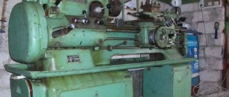
Single-column turning lathe 1516. Purpose and scope
The single-column rotary lathe model 1516 is a universal machine and is designed for processing a variety of products made of ferrous and non-ferrous metals in small-scale and mass production.
Model 1516 is common among rotary lathes in the former USSR. The machine allows turning parts with a diameter of up to 1600 mm, a height of up to 1 meter and a weight of up to 6300 kg . The machine was exported to many countries around the world.
The design of the 1516 machine is unified with the design of the 1512 machine and differs only in the dimensions of the faceplate and the power of the electric motor.
The machine can perform cylindrical and conical turning and boring, turning of planes, drilling, countersinking and reaming of holes, as well as semi-finishing and finishing turning of flat end surfaces.
Operating principle and design features of the machine
The machine has two supports :
- vertical with a five-position turret with automatic rotation and locking at each position
- horizontal (side) with four-position tool holder
The technological capabilities of the machine are significantly expanded with the help of a self-centering faceplate supplied upon special order, devices (for thread cutting, processing of conical surfaces, turning shaped surfaces of bodies of revolution along a copier, processing parts on stops) and a device for processing with cooling.
The following operations can be performed on the machines:
- turning cylindrical and conical surfaces;
- boring of cylindrical and conical surfaces;
- turning flat end surfaces using vertical and lateral supports.
In addition, a vertical support can be used to grind flat end surfaces while maintaining a stepwise constant cutting speed in finishing and semi-finishing modes; drilling, countersinking and reaming; Grooving and parting.
When using special devices and devices that are supplied with the machines upon special order for an additional fee, the machines can produce:
- processing of parts according to specified dimensions (on stops);
- cutting threads, turning and boring conical surfaces;
- processing of shaped surfaces of bodies of rotation using a copier (electrocopier);
- processing of parts with cooling.
In the usual version, the machines are supplied with a vertical turret support, which has a mechanical rotation and clamping of the turret head, and a side support.
In addition, upon special order, for an additional fee, a machine with a self-centering faceplate with manual clamping of the product can be supplied.
All accessories can be mounted on the machine at the same time, with the exception of cooling, which cannot be installed simultaneously with the self-centering faceplate.
Due to the fact that the installation of fixtures requires significant changes and modifications to the machine, orders for the manufacture of fixtures for previously supplied machines cannot be fulfilled. Accessories are supplied only with the machine.
The significant power of the main drive electric motor, the high rigidity of the base parts and the sufficient strength of all elements of the kinematic chain, combined with wide ranges of control of the faceplate speeds and feed rates, allow the machines to perform highly productive work at high-speed cutting conditions.
Main technical characteristics of screw-cutting lathe 1516
Developer: Krasnodar Machine Tool Plant named after Sedin.
Manufacturer: Krasnodar Machine Tool Plant named after Sedin.
The main parameters of the machine are in accordance with GOST 44-93. Rotary lathes. Basic parameters and dimensions. Standards of accuracy and rigidity.
- Machine accuracy class N according to GOST 8-77.
- The largest diameter of the workpiece being processed is Ø 1600 mm
- The highest height of the processed workpiece is Ø 1000 mm
- Diameter of the washer - Ø 1400 mm
- The largest weight of the processed workpiece is 6300 mm
- Faceplate rotation speed - 4..200 rpm, 18 steps
- Electric motor power - 30 kW
- Full weight of the machine – 20 t
Modifications of the rotary-turning machine, single-column 1516
1516.000, 1516-1, 1516-2, 1516.300, 1516.400 - universal single-column rotary lathe
1516F1, 1516PF1, 1516F1.041, 1516F1.300, 1516F1.323, 1516F1.4 00, 1516F1.423 - rotary lathe with digital display — digital display device
1516F2, 1516F3, 1516F3.271, 1516F3.471, 1516MF4 - rotary lathe with CNC - numerical control device
Purpose and scope of application, passport
The universal turning lathe 1516 is capable of processing workpieces made of ferrous and non-ferrous metals, and the main technical characteristics and parameters correspond to GOST 44–93. In addition to its use in domestic enterprises, the machine was exported to dozens of countries around the world.
The single-column design with a faceplate at the bottom and two supports at the top helps reduce the workload on all the main components of the machine. Vertical and horizontal supports allow the following operations on the machine:
- boring holes;
- trimming;
- milling;
- grinding;
- drilling holes of various diameters;
- turning of cylindrical and conical surfaces;
- thread cutting;
- using special tools to create curved surfaces.
Some operations will require additional equipment for the machine. The equipment operates with casting, rolling and forgings.
The lathe's passport can be downloaded for free from the link - Passport of the universal single-column rotary lathe 1516.
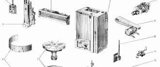
Arrangement of the components of the rotary lathe 1516
Location of machine components 1516
List of components of the machine 1516
- Table – 30
- Faceplate guard - 31
- Vertical support - 650
- Control pendant - 990
- Control panel suspension - 99
- Crossbar - 50
- Cross member movement mechanism - 57
- Bed - 10
- Mechanism for manual movement of vertical support - 420
- Vertical support feed box - 40
- Gearbox - 21
- Casing - 25
- Mechanism for transmitting movement to feed - 15
- Lubrication - 34
- Horizontal caliper (side) - 66
- Feed box horizontal caliper (side) - 46
A distinctive feature of the design of the machines is that most assembly units are made as independent products, which facilitates assembly not only during the manufacturing process, but also during repairs.
Location of components
The supporting structure of the entire machine, on which all the main components of the unit are mounted, including the body - a large, heavy hollow cast frame. The machine must be secured to a thick foundation layer, which will eliminate unnecessary vibration and allow it to support the weight of the unit.
Flat guides are located on the front side of the bed. The caliper and cross member move along these structures. The main drive gearbox is located on the other side of the frame. Devices for moving the crossbar are located on the top of the frame.
The assembly of the entire rotational system is located on the table body. It is based on:
- Faceplate. During the working process, it rests on circular guides, which are located in the upper part of the body. There are T-shaped grooves on the front part of the faceplate. The workpiece being processed is attached to them using additional equipment. The faceplate itself has a built-in workpiece clamping mechanism. The quality of processing and the safety of the entire work process depend on this module.
- Spindle. The upper part is fixed to the center of the faceplate. It rests on the angular contact bearing from below. The function is to transmit, the main movement is from the drive.
- The faceplate drive is designed to transmit, to impart movement to the spindle.
For the vertical arrangement of machine parts there is a stand with a crossbar. The manufacturer has provided for emergency situations, so the stand is made with a safety margin.
A traverse with two calipers moves along the racks, which is easy to fix in the desired position. One of the calipers is a revolving caliper, and the second is a boring caliper. The turret contains a carriage and a slider with a turret head. On the second support there is a slider with a tool holder.
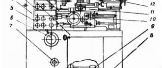
Location of controls for rotary lathe 1516
Location of controls for rotary lathe 1516
List of machine controls 1516
- Handle for fastening the cutting head of the side support
- Screw for fixing the cutting tool arbor in the turret socket
- Vertical support slider fixing screw
- Nuts for fastening the rotary slide of the vertical support
- Handle for connecting the machine to the electrical network
- Crossbar clamp handle
- Buttons for moving the crossbar “up”, “down”
- Square worm for rotating the vertical slide slide
- Vertical support fixing screw
- Flywheel for manual vertical movement of the vertical support slider
- Flywheel for manual horizontal movement of vertical caliper
- Control pendant
- Side caliper slider fixing screw
- Side support fixing screw
- Flywheel for manual horizontal movement of the side slider
- Flywheel for manual vertical movement of the side support
Passport details
Vertical lathe 1516 passport, which contains additional characteristics:
- accuracy class – N according to GOST 8-71;
- remote control of tool selection – Yes;
- remote feed control – Yes;
- T-shaped slots, size - 28H13 mm;
- motion control dials with a division value of 0.05 mm.
Download the passport (operating instructions) of the rotary lathe 1516
Control panel for rotary lathe 1516
Control panel for rotary lathe 1516
List of controls on the machine control panel 1516
- "GENERAL STOP" button
- “NO LUBRICATION” warning light in the main drive
- Main drive STOP button
- Main drive START button
- Switch for turning on and off the vertical support brake
- Turret rotation and clamp button
- Switch for setting working feeds and installation movements of the vertical support
- Vertical support feed switch
- Switch for the direction of movement of the vertical support
- Signal light “VERTICAL CALIPER IN OPERATION”
- Light switch on/off
- Signal light “SIDE CALIPER IN OPERATION”
- Side support movement switch
- Side support feed switch
- Switch for setting working feeds and installation movements of the side support
- Switch for turning on and off the brake of side caliper movements
- Switch for faceplate revolutions per minute
- Switch for switching on and off step-constant cutting speed
- Faceplate START button
- Faceplate "STOP" button
- Switch for turning on and off the faceplate jog start
Kinematic diagram of machine 1516
Kinematic diagram of rotary lathe 1516
The kinematic diagrams of machines 1512 and 1516 are similar to each other and differ from each other only in the kinematics of the chain of the feed motion transmission mechanism and the number of teeth of the table gears.
Due to the different number of teeth on the table gears, machines 1512 and 1516 have different speed limits for the faceplate speeds with the same gearbox.
The kinematics of the chains of the feed motion transmission mechanism are different for the machines, but their gear ratios are selected in such a way that the total gear ratio of the kinematic chain from the faceplate to the feed box is the same for both machines. This allows you to use the same feed boxes and obtain the same feed amounts.
Gearbox of machine 1516
The gearbox is used to ensure rotation of the faceplate, as well as starting, stopping and changing speeds. Rotation is transmitted to the input shaft of the gearbox from the main drive electric motor through a V-belt drive. The gearbox provides the faceplate with 18 speed levels.
The gearbox is controlled remotely from a pendant remote control.
The presence of electromagnetic clutches in the gearbox allows you to switch speeds on the go and thereby ensure the maintenance of a stepwise constant cutting speed when processing end surfaces.
The gearbox has six shafts mounted on rolling bearings in a housing with a parting plane along the shaft axes for ease of assembly.
At higher speeds, the start is carried out in stages in two, three or four stages. The number of acceleration stages increases with increasing speed of the faceplate.
Switching of clutches during stepwise acceleration is carried out automatically (for a detailed description, see Part 2 of the Operating Manual 'Electrical equipment of machine tools').
Changing the speed from 1st to 12th stage is carried out by turning on the corresponding combinations of electromagnetic clutches.
To enable the jog mode of operation of the faceplate, which is used when installing and aligning the part, it is necessary to place the switch on the pendant control panel in the “Jog start” position of the faceplate and press the “Start” button of the faceplate.
There are no special braking devices in the gearbox, and the faceplate is braked by simultaneous activation of three electromagnetic clutches.
Machine table
There are no fundamental design differences between the tables of machines 1516 and 1512. The machine parts are similar and differ from each other only in size.
The table consists of a body with circular guides, a faceplate with a spindle and a faceplate drive.
The table body is a cast iron with a developed system of ribs, giving it greater rigidity.
At the top of the table body there are annular projections that fit into the annular grooves of the faceplate, forming a labyrinth. This prevents lubricant from splashing and protects against chips, cast iron dust, emulsion and other contaminants getting inside the table.
The faceplate is driven from the gearbox through a pair of bevel gears with a circular tooth, then through a cylindrical helical pair: a gear and a ring gear rigidly connected to the faceplate.
Machine feed boxes
The design of the feed boxes of the lateral and vertical supports is the same.
The vertical support feed box is mounted on the right end of the cross member; side caliper feed box - directly to its body.
The feed box body is a box-shaped cast iron with sufficient rigidity. All feed box shafts are mounted on rolling bearings.
The feed boxes are driven from a vertical splined shaft, which receives rotation from the output shaft of the gearbox through the mechanism for transmitting movement to the feed (see Fig. 6).
The feed boxes provide the calipers with 18 working feeds and 18 speeds of installation movements. This is achieved by switching on the appropriate combinations of electromagnetic clutches of the feed boxes (for the switching diagram of electromagnetic clutches, see Part 2 of the Operating Manual 'Electrical equipment of machine tools*).
All gears of the feed boxes are in constant engagement.
A turret head with five slots and holes for attaching a tool is mounted on a cylindrical bushing. Changing the positions of the turret is carried out remotely from a pendant control panel. By pressing the “Turret Head” button, the electric motor for turning the turret head, mounted on the upper end of the slide, is turned on. Rotation from the electric motor is transmitted through gears to the drive shaft.
The main movement (rotation of the faceplate) is transmitted from the electric motor 1 through the V-belt transmission 2 - 3 to shaft I, then through the gearbox, shaft V, bevel gears 25 - 26 and wheels 27-28 is transmitted to the faceplate. The gearbox is equipped with eight electromagnetic clutches, the switching of which allows you to provide the faceplate with 18 rotation speeds ranging from 5 to 250 rpm.
The feeds of the calipers (revolving and side) are borrowed from the faceplate through two independent feed boxes with the same kinematics. Each box is equipped with eight electromagnetic clutches, switching which makes it possible to obtain 16 feed rates for both calipers.
Horizontal feed of turret support . From shaft VIII of the faceplate through gear 28 - 27, bevel gears 26 - 25, 24 - 23, gear 29 - 30 and bevel pairs of wheels 31 and 53, the movement is transmitted to shaft XII of the feed box (shown separately at the top left). From the feed box, the shaft XX of the caliper mechanism receives rotation, and then through gears 52 and a screw pair 65, the turret caliper receives horizontal feed.
Vertical feed of the turret support . From shaft VIII of the faceplate to shaft XXI of the feed box, rotation is carried out along the same chain; Then, through bevel gears 55 - 56, a cylindrical pair of wheels 57, a conical pair 58 and a screw pair 59, the turret caliper receives the feed movement.
Horizontal feed of side support . As before, the movement goes from shaft VIII of the faceplate to shaft XII of the feed box, then through the feed box to shaft XX and then through gears 39 - 41 and screw pair 42, the side caliper receives feed.
Vertical feed of side support . From the faceplate shaft to the feed box shaft XII, the movement proceeds along the same chain, then through the feed box the shaft XXI of the caliper mechanism receives rotation and through the bevel gears 35-36 and the screw pair 43 the side caliper receives feed.
Both supports receive accelerated movement
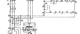
Electrical circuit of the power supply of the machine 1516
Electrical circuit of the power supply of the rotary lathe 1516
Characteristics of the electrical equipment of the machine 1516
The electrical equipment of machine tools consists of electric motors, electrical controls, limit switches to limit the movement of moving parts of the machine and control equipment.
The machines are equipped with five three-phase asynchronous electric motors with a squirrel-cage rotor:
- main drive motor 1M1;
- oil pump drive motor 1M2;
- cross member movement motor 1M3;
- motor for installation movements of the upper support, installation movements of the side support 4M1 and three single-phase asynchronous capacitor electric motors with a squirrel-cage rotor to drive the lubricator of the lubrication system;
- cross member motor 1M4;
- upper support motor 2M2 and 2M3
The following voltage values are accepted on the machine
- 380V three-phase alternating current, frequency 50 Hz - power supply of power circuits;
- 110V single-phase alternating current - power supply to coils of magnetic starters and single-phase electric motors;
- 36V single-phase alternating current - power supply for the circuit for selecting the direction of travel of the stepper finder;
- 24V - DC power supply for local lighting lamps;
- 24V - DC power supply for control circuits and electromagnetic couplings;
- 90V - DC power supply to the stepper finder coils.
All electrical equipment for controlling the machine is located in the niche of the machine. The machine is controlled from a pendant control panel.
The electrical equipment of the machine performs the following functions:
- Faceplate control:
- start-up in operating mode;
- start in jog mode;
- step change in speed with a rotating faceplate;
- maintaining a stepwise constant cutting speed when turning end surfaces with the upper support (changing the speed of rotation of the faceplate using a cam rack and a limit switch);
- faceplate stop.
Caliper control:
- working feeds (feed selection and switching on);
- installation movements (selection of movement speed and switching on).
Moving the cross member.
Description of electrical equipment operation
The electrical circuit provides for the following operations
- starting and stopping the main drive electric motor and the lubrication system electric motor;
- raising and lowering the cross member.
Main drive motor control
The main drive electric motor is controlled from a pendant control panel using buttons 1Кн2 - “Start” and IKHI - “Stop”.
When you press the 1Kn2 - “Start” button, the main drive starter 1K1 is turned on. At the same time, the 1P1 relay for limiting the idle speed of the main drive electric motor is turned on, which operates with a time delay. If the faceplate is not turned on during this time, the open contact of this relay (circuit 4) will turn off the main drive starter.
The main drive electric motor is turned off by pressing the IKHI - “Stop” button.
When the faceplate is turned on, the IKHI button is blocked by the closing contact of the step finder SHIT. The main drive motor can only be turned off after the faceplate has been turned off and the step finder is in the zero position.
Characteristics of the electrical equipment of the machine 1516
The electrical equipment of machine tools consists of electric motors, electrical controls, limit switches to limit the movement of moving parts of the machine and control equipment.
The machines are equipped with five three-phase asynchronous electric motors with a squirrel-cage rotor:
- main drive motor 1M1;
- oil pump drive motor 1M2;
- cross member movement motor 1M3;
- motor for installation movements of the upper support, installation movements of the side support 4M1 and three single-phase asynchronous capacitor electric motors with a squirrel-cage rotor to drive the lubricator of the lubrication system;
- cross member motor 1M4;
- upper support motor 2M2 and 2M3
The following voltage values are accepted on the machine
- 380V three-phase alternating current, frequency 50 Hz - power supply of power circuits;
- 110V single-phase alternating current - power supply to coils of magnetic starters and single-phase electric motors;
- 36V single-phase alternating current - power supply for the circuit for selecting the direction of travel of the stepper finder;
- 24V - DC power supply for local lighting lamps;
- 24V - DC power supply for control circuits and electromagnetic couplings;
- 90V - DC power supply to the stepper finder coils.
All electrical equipment for controlling the machine is located in the niche of the machine. The machine is controlled from a pendant control panel.
The electrical equipment of the machine performs the following functions:
- Faceplate control:
- start-up in operating mode;
- start in jog mode;
- step change in speed with a rotating faceplate;
- maintaining a stepwise constant cutting speed when turning end surfaces with the upper support (changing the speed of rotation of the faceplate using a cam rack and a limit switch);
- faceplate stop.
Caliper control:
- working feeds (feed selection and switching on);
- installation movements (selection of movement speed and switching on).
Moving the cross member.
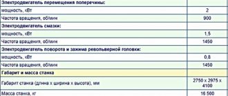
Technical characteristics of the rotary lathe 1516
| Parameter name | 1512 | 1516 |
| Main settings | ||
| The largest diameter of the product processed by vertical and lateral supports, mm | 1250 | 1600 |
| Maximum height of the workpiece, mm | 1000 | 1000 |
| Faceplate diameter, mm | 1120 | 1400 |
| Maximum weight of the installed product, kg | 4000 | 6300 |
| at 5-80 faceplate revolutions per minute | 3200 | 6300 |
| at 100 faceplate revolutions per minute | 3000 | |
| at 125 faceplate revolutions per minute | 2700 | |
| at 160 faceplate revolutions per minute | 1900 | |
| at 200 faceplate revolutions per minute | 1300 | 2400 |
| at 250 faceplate revolutions per minute | 1000 | |
| Vertical support | ||
| Maximum horizontal movement, mm | 775 | 950 |
| Maximum vertical movement, mm | 700 | 700 |
| Price for dividing the horizontal and vertical movement dial, mm | 0,05 | 0,05 |
| Horizontal and vertical movement per one revolution of the dial, mm | 2,5 | 2,5 |
| Maximum angle of rotation of the caliper slider, degrees | 45 | 45 |
| Caliper slider rotation dial division price, min | 1 | 1 |
| Caliper slider rotation scale division value, deg | 1 | 1 |
| Diameter of caliper turret holes, mm | 70A | 70A |
| The largest cross-sectional dimensions of the cutter holder (width x height), mm | 25 x 40 | 25 x 40 |
| Horizontal caliper (side) | ||
| Maximum horizontal movement, mm | 630 | 630 |
| Maximum vertical movement, mm | 1000 | 1000 |
| Price for dividing the horizontal and vertical movement dial, mm | 0,05 | 0,05 |
| Horizontal and vertical movements per one revolution of the dial, mm | 2,5 | 2,5 |
| Cross member | ||
| Maximum displacement, mm | 660 | 660 |
| Travel speed, mm/min | 400 | 400 |
| Switching stops | Available | Available |
| Blocking movement during cutting | Available | Available |
| Machine mechanics | ||
| Number of faceplate speeds | 18 | 18 |
| Faceplate revolutions per minute | 5 — 250 | 5 — 250 |
| Number of caliper feeds | 18 | 18 |
| Vertical and horizontal feeds of calipers, mm/rev | 0,03 — 12,5 | 0,03 — 12,5 |
| Maximum permissible cutting force with two supports, kgf | 4500 | 4500 |
| Speed of installation movements of calipers, mm/min | 5 — 1800 | 5 — 1800 |
| Drive and electrical equipment of the machine | ||
| Type of supply current | AC three-phase | AC three-phase |
| Main motion drive electric motor, kW | 30 | 30 |
| Electric motor for caliper installation movements, kW | 3 | 3 |
| Electric motor for moving the crossbar, kW | 2 | 2 |
| Lubrication motor, kW | 1,5 | 1,5 |
| Electric motor for turning and clamping the turret head, kW | 0,8 | 0,8 |
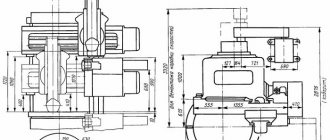
| Dimensions and weight of the machine | ||
| Machine dimensions (length x width x height), mm | 2750 x 2975 x 4100 | 3170 x 3030 x 4100 |
| Machine weight, kg | 16 500 | 20 000 |