Information about the manufacturer of dividing heads UDG-200 (UDG-D-200)
The developer and manufacturer of the UDG-200 (UDG-D-200) dividing heads until 1990 was the Leningrad Optical-Mechanical Association LOMO .
Currently, the production and sale of universal dividing heads UDG-160 (UDG-D-160), UDG-200 (UDG-D-200), UDG-250 (UDG-D-250), UDG-320 (UDG-D- 320) is carried out by Production , which was founded in 1990 on the basis of OJSC LOMO.
Products manufactured by the Leningrad Optical-Mechanical Association LOMO
- UDG-100 (UDG N-100)
- universal dividing head 100 (Ø 200) - UDG-135 (UDG N-135)
- universal dividing head 135 (Ø 270) - UDG-160 (UDG-D-160)
- universal dividing head Ø 160 - UDG-200 (UDG-D-200)
- universal dividing head Ø 200 - UDG-250 (UDG-D-250)
- universal dividing head Ø 250
Sequence of setup and application
The transitions performed depend on the type of device and its characteristics, which are set depending on the value of the scale division. In particular, for nodes of the seventh/eighth degree of accuracy, the regulatory data of GOST 1.758 are used, and for nodes of the ninth degree of accuracy - GOST 1.643.
The main adjustment of the head is to determine the size of the pitch circle sector. The initial data for the calculation are the diameter of the circle and the number of sectors into which it will need to be divided. The setup occurs in the following sequence:
- convert 360° of the full diameter of the circle into the required number of divisions on its sectors;
- determine the sine of the angle resulting from the calculation;
- rotate the device disk to a given angle;
- clamp the assembly body with a handle or clamping mechanism and install the working tool.
The formula for calculating the required dividing angle is usually given in the dividing head manufacturer's instructions. Next, the part to be milled is secured to the machine mandrel, and the required operation is performed by performing a longitudinal feed of the table. The feed pitch depends on the type of processing: for example, for tooth shaping, it is equal to the distance between the cavities of adjacent teeth. In order to increase productivity, after each cycle the table with the workpiece returns quickly to its original position. Fixation to the hole selected in the measuring disk is performed using springs.
UDG-200 (UDG-D-200) universal dividing head. Purpose, scope
The dividing head UDG-200 (UDG-D-200) makes it possible to perform various milling, gear hobbing, boring, drilling, marking and other work related to rotating a part at a given angle.
Parts can be processed using the UDG-200 in centers, in a chuck or on a spindle mandrel.
Using the universal dividing head UDG-200, you can perform the following operations:
- direct division of circles by a multiple of 24, i.e. on 2, 3, 4, 6, 8, 12, 24
- simple division of circles into a number of parts from 2 to 400 and into some numbers over 400
- differential division of circles into a number of parts from 43 to 400 without intervals
- milling of spirals with pitches from 25 to 400 mm
- gear milling
- setting the axis of the workpiece at the required angle relative to the machine table
- various works on milling machines related to dividing a circle into unequal parts in degrees, cutting spirals, etc.
Dividing heads. General information
Dividing heads are a device for universal and cantilever milling machines, which significantly expands their technological capabilities.
They are used in the manufacture of various tools (mills, reamers, countersinks, taps), normalized machine parts (bolt heads, nut faces, castle nuts), when milling gears, sprockets, cutting grooves and splines at the ends (gear couplings) and other parts . Dividing heads are used to secure and divide workpieces into equal parts when milling squares, hexagons, cutting gears, sprockets and other similar work, and to rotate workpieces at a given angle. Universal dividing heads also serve to impart rotation of the workpiece when cutting helical grooves on universal milling machines.
Depending on the head design, the workpiece circumference can be divided into equal or unequal parts. When cutting helical grooves, the workpiece is simultaneously subjected to continuous rotational and translational movements, as, for example, when processing chip grooves in drills, cutters, taps, reamers and countersinks.
Dividing heads serve:
- to set the axis of the workpiece at the required angle relative to the machine table
- for periodically rotating the workpiece around its axis at a certain angle (dividing into equal and unequal parts)
- for continuous rotation of the workpiece when cutting helical grooves or helical teeth of gears
Dividing heads are:
- Limb with dividing disks:
- universal
- semi-universal
- simple division
- direct division
Typically, dividing heads are made single-spindle. Sometimes multi-spindle (two- and three-spindle) ones are used for simultaneous processing of two or three workpieces, respectively. Limbless dividing heads allow the dividing process to be carried out using replaceable gears. In this case, the handle of the dividing head is turned one or more full turns. However, the design and kinematic diagram of dialless dividing heads is much more complicated than dial ones.
Universal dividing heads UDG-D
Previously, our industry produced universal dividing heads UDG N-100, UDG N-135 and UDG N-160 with center heights H = 100, H = 135 and H = 160 mm.
, the largest diameter of the workpiece being processed D is taken as the main size of the dividing heads . According to the standard, a series of six standard sizes of heads is adopted: D = 160; 200; 250; 320; 400 and 500 mm. Model names UDG-D-160, UDG-D-200, UDG-D-250, UDG-D-400, UDG-D-500.
The gear ratio of the worm pair of these heads is 1: 40 (N=40), i.e., the head spindle rotates a full turn in 40 turns of the handle.
The range of division of the workpiece circumference is up to 400 parts, including prime numbers.
Universal dividing heads allow dividing workpieces using three methods: direct, simple and differential and are used to complete milling machines of domestic and foreign production.
Each size of the machine (according to the width of the table) must correspond to a certain standard size of the dividing head. Thus, for cantilever milling machines No. 2 (with a table width of 320 mm) we recommend a dividing head with the largest diameter of the workpiece being processed D = 250 mm, and for milling machines No. 3 (with a table width of 400 mm) - an UDG-D-320 dividing head etc.
Designation of high-precision (P) dividing heads:
- UDG-D-160 - 7036-0051P
- UDG-D-200 - 7036-0052P
- UDG-D-250 - 7036-0053P
- UDG-D-320 - 7036-0054P
- UDG-D-400 - 7036-0055P
Designation of dividing heads of normal (N) accuracy:
- UDG-D-160A - 7036-0051
- UDG-D-200A - 7036-0052
- UDG-D-320A - 7036-0054
- UDG-D-250A - 7036-0053
- UDG-D-400A - 7036-0055
What it is?
For processing parts with a complex configuration, making grooves and grooves, processing on one type of equipment is not enough. The part has to be removed and placed on another machine. In this case, it is necessary to set it with high accuracy relative to the base and the already processed finishing dimensions.
To mill all surfaces, drilling and boring the side planes, milling heads are used. They significantly increase the technological capabilities of the machine, turning it into a universal, multifunctional unit. Devices change the position of the tool relative to the spindle axis, allow you to do plane processing on turning equipment, and work without stopping with different tools.
Important!
CNC heads have a complex mechanism inside that automatically changes the position of the cutting tool. They work in harmony with the equipment, according to one program.
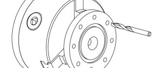
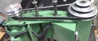
Dividing head design
To process elements of parts located on conical surfaces, for example, when milling cavities to form teeth of bevel wheels, countersinks, countersinks, etc., the body is rotated around a horizontal axis in a vertical plane at a given angle relative to the base of the head.
Dividing heads are usually available for installation on the left end of the workbench. However, domestic machine tool factories produce dividing heads designed for installation on the right side of the table.
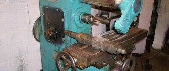
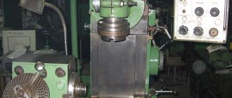
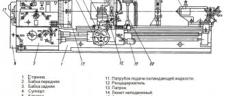
The UDG-D-200 dividing head has a cast iron base 16 with tie rods 17, on which a housing 18 is installed. By loosening the nuts 19 (Fig. 3), you can rotate the housing to a certain angle. The rotation angle is measured using the scale and vernier 20 (see Fig. 2).
On the supporting plane of the base of the dividing head there are two keys that are precisely fitted parallel to the spindle, which are used to install the head in the groove of the milling machine table. The housing contains a spindle with a through hole. The ends of the spindle are bored to a Morse taper. A center 21 is installed at one end, and a mandrel 13 (see Fig. 1) for differential division is installed at the other. The front end of the spindle has a thread and a centering belt 22 (see Fig. 2) for installing and fastening a flange with a self-centering chuck or a driver. On the spindle collar there is a dial 9 of direct division, which has twenty-four holes.
On the spindle, in its middle part, sits a worm wheel with a circular groove at the end, into which the end of a clamp 23 mounted in the housing 18 fits. The worm wheel receives rotation from a worm located in an eccentric sleeve. The worm can be engaged or disengaged by turning the eccentric sleeve using handle 24 (see Fig. 3) with sector 25.
The dividing disk is mounted on a shaft mounted in sliding bearings in cover 26 (see Fig. 2). The cover is fixed on the body 18 with a centering bore and is fixedly attached to the base.
Bevel and cylindrical gears are installed on the shaft of the dividing disk, as well as a drive bar that has a handle with a lock that moves along the required row of holes on the dividing disk. A sliding sector 27, consisting of rulers 28 and a clamping screw 29, is pressed to the dividing disk using a spring, with the help of which the rulers are installed at the required angle. The spring washer prevents spontaneous rotation of the sector.
The mechanical drive shaft 30 from the machine is mounted in plain bearings and located in a sleeve 31 with a flange. The sleeve is attached to cover 26. At the end of the shaft there is a bevel gear, which is in constant mesh with the bevel gear sitting on the shaft of the dividing disk. The dividing disk is fixed in the required position with stopper 7.
Tailstock
The tailstock serves to support the second end of the workpiece when installing it in the centers or chuck of the dividing head. The center of the headstock can be moved in horizontal and vertical directions. At the base 32 there is a housing 33, which is connected to the rail by a pin. By rotating the head of the gear shaft, the housing can be raised, lowered and rotated relative to the axis of the pin. In the required position, the tailstock is secured to the machine table using bolts and nuts.
The movement of the quill 34 with the half-center 35 is carried out by rotation of the handwheel 36 mounted on the screw.
On the supporting plane of the base there are two guide keys, aligned with the axis of the quill; The keys ensure that the centers of the dividing head and the tailstock coincide when they are installed on the machine table.
Lunette
The steady rest is an additional support when processing long and thin parts. In its body 37 there is a screw that moves with the help of a nut 38. The screw has a prismatic head 39; with the help of a locking screw 40 the head can be secured at the required height.
Where to order and buy?
CNC heads are offered by companies that manufacture tools and fixtures for CNC machines. Each company that produces turning and milling equipment offers a large list of accessories for them, including milling equipment of various types. Orders can be made online from official representatives.
Milling heads are widely used in factories to quickly produce complex parts from a single setup. Hobbyists install devices on home machines to make them more functional and versatile.
List of controls for the dividing head UDG-200
- Locking handle. Fixing holes on the pitch circle of the pitch disc
- Screw. Fastening the head housing to the base
- Stopper. Spindle lock
- Screw. Fastening the eccentric bushing with a worm
- Eccentric bushing handle. Turning the worm on and off
- Screw. Leash attachment
- Screw. Attaching the locking handle
- Latch. Fixing the direct division dial
- Screw. Attaching the indexing disc stopper pin
- Stopper pin. Locking the dividing disk
- Drive bushing. Guitar mount
- Flywheel. Tailstock half-center movement
- Screw. Tailstock half-center mount
- Cylindrical. Moving the tailstock wheel in the vertical direction
- Bolt. Tailstock housing mount
- Limiter. Aligning holes on the dividing disk when dividing
- Screw. Fastening the bar with handle and lock
Extension heads
Extension heads are one of the most common types of tooling. They allow you to increase the length of the spindle, narrow its outer diameter, and reduce the collision between the spindle and the workpiece, which is important when machining deep grooves.
UDG-200 Lubrication points of the universal dividing head
Lubrication points of the universal dividing head UDG 160
- I - Disc shaft and bevel gear. Lubricate daily
- II - Cylindrical and bevel gears. Pouring 100 g of oil through the lid
- III - Front spindle bearing. Lubricate daily
- IV - Worm pair. Pouring 200 g of oil into the housing
- V - Rear spindle bearing. Lubricate daily
- VI - Quill and tailstock screw. Lubrication every two days
- VII - Dividing head drive shaft. Lubrication every two days
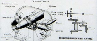
UDG-200 Kinematic diagram of the universal dividing head
Kinematic diagram of the universal dividing head UDG-200
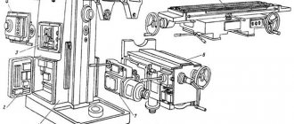
In simple division, rotation of the spindle 1 is transmitted from the handle 2 with a lock through a pair of spur gears 3, a worm 4 and a worm wheel 5 located in the middle part of the spindle. In this case, the dividing disk 6 must be secured using the stopper 7, and the clamp 8 of the direct division dial 9 is turned off.
In differential division, the angle of rotation of the spindle is determined by the amount of rotation of the handle with the lock relative to the dividing disk and the amount of rotation of the disk itself, which receives rotation from the spindle through the replaceable gears 10 of the guitar 11 and a pair of bevel gears 12. To transmit rotation from the spindle to the replaceable gears of the guitar, a mandrel 13 is used, on the cylindrical neck of which a replaceable gear 14 is installed. In this case, the dividing disk must be released from the stopper, and the direct division dial lock must be turned off.
When cutting a spiral, the spindle receives rotation from the lead screw of the milling machine through the replaceable gears of the guitar, a pair of bevel gears 12, an intermediate shaft 15, cylindrical gears 3, a worm 4 and a worm wheel 5. In this case, the dividing disk must be released from the stopper, and the dial clamp must be directly division is turned off.
Universal heads
Universal milling heads are distinguished by the ability to change the angle of rotation of the output spindle relative to the input spindle (machine spindle). With such a head, a 3-axis machine can receive 2 more working directions. Moreover, if positioning in these directions is carried out automatically, then it can turn into either a machine with 3+2 axes, or a full-fledged 5-axis machine with interpolation along all axes.
This group also includes various fork heads, so called because of their design features. This type of head is widely used in longitudinal milling (gantry machines) and some turning and milling machining centers.
Operating procedure
Direct division
Direct division is used when dividing a circle into 2, 3, 4, b, 8, 12 and 24 parts in cases where great accuracy is not required.
When dividing directly, you must:
- disengage the worm from engagement with the worm wheel by turning handle 24 (see Fig. 3) until it stops
- release the direct division dial clamp from engagement
The spindle is turned by hand by rotating the workpiece or chuck. The angle of rotation is measured using a degree scale marked on the direct division dial and a line on the front spindle bushing.
Secure the spindle in the required position using clamp 23 (see Fig. 2).
When dividing into parts or faces, the calculation is made using the formula
N = 360°/a(1)
where n is the number of parts or faces; A
a is the spindle rotation angle.
Simple division
A simple division of a circle into equal and unequal parts is carried out with a stationary dividing disk using a handle with a lock. The amount of rotation of the handle is measured by the holes on the dividing disk and is fixed with a locking rod.
Differential division
Dividing a circle into a number of parts greater than 42, not a multiple of the number of holes on the dividing disk, can be done by a differential method, the essence of which is that the angle of rotation of the spindle is determined by the amount of rotation of the handle with the lock relative to the dividing disk and the amount of rotation of the disk receiving rotation from the spindle through replacement guitar gears.
The guitar is mounted on a cylindrical shank on which it can be rotated and secured in the desired position. To install replacement gears, the guitar is equipped with movable pins and adapter bushings. To transmit rotation to the replaceable gears, a mandrel is inserted into the rear cone of the spindle, onto the cylindrical neck of which the replaceable gear is installed.
Before starting work, turn the handle to check the smooth rotation of all installed gears.
When performing differential division, the indexing disk stop must be turned off.
The adjustment procedure for differential division is the same as for simple division.
Differential division is only possible with the spindle in a horizontal position.
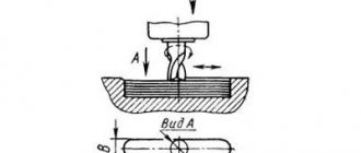
Spiral Grooving
Milling of spiral grooves is carried out by longitudinal movement of the milling machine table and simultaneous rotation of the part fixed in the dividing head relative to its axis. For coordinated rotation of the part with longitudinal movement of the table, a guitar is installed with a set of replaceable gears that transmit rotation from the machine lead screw to the dividing head spindle.
Multi-spindle heads
Multi-spindle milling heads are used when it is necessary to expand the technological capabilities of existing machines in small-scale and mass production, including on outdated equipment. On such machines, after a slight readjustment, it is possible to process different parts that have structural differences and are part of the same type.
Multi-spindle milling heads are divided into 2 types: with variable distances between axes and with fixed ones.
Technical characteristics of the head UDG-200
| Parameter name | UDG-160 | UDG-200 | UDG-250 | UDG-320 |
| Main settings | ||||
| Accuracy class according to GOST 8-82 | P | P | P | P |
| Center height, mm | 85 | 105 | 130 | 165 |
| Largest diameter of the workpiece, mm | 160 | 200 | 250 | 320 |
| Distance from the base of the dividing head to the end of the spindle in its vertical position: no more than, mm | 180 | 235 | 280 | 350 |
| Angle of rotation of the spindle in the vertical plane down from the center line: not less than, degrees | 5 | 5 | 5 | 5 |
| Angle of rotation of the spindle in the vertical plane upwards from the center line: not less than, degrees | 95 | 95 | 95 | 95 |
| Takar chuck diameter, mm | 100 | 125 | 160 | 160 |
| Spindle taper | Morse No. 2 | Morse No. 3 | Morse No. 4 | Morse No. 5 |
| Spindle end thread | M33 | M39 | M52 | M60 |
| Spindle hole diameter, mm | 14,9 | 20,2 | 26,5 | 38,2 |
| Worm gear ratio | 1 : 40 | 1 : 40 | 1 : 40 | 1 : 40 |
| Division range including prime numbers | 2..400 | 2..400 | 2..400 | 2..400 |
| Diameter of holes for replacement wheels, mm | 20x19 | 20x19 | 20x19 | 32x19 |
| Number of dividing disk holes | 16,19,23 30,33,39 49 | 16,17,19 21,23,29 30,31 | 16,17,19 21,23,29 30,31 | 16,17,19 21,23,29 30,31 |
| Number of dividing disc holes on the other side | 17,21,29 31,37,41 54 | 33,37,39 41,43,47 49,54 | 33,37,39 41,43,47 49,54 | 33,37,39 41,43,47 49,54 |
| Dividing value of the direct division dial, deg | 15 | 15 | 15 | 15 |
| Replaceable gear module | 1,5 | 1,5 | 1,5 | 2,5 |
| Width of guide keys, mm | 12 | 14 | 18 | 18 |
| Dimensions and weight of the dividing head | ||||
| Overall dimensions of the head base, mm | 212 x 156 | 260 x 180 | 260 x 180 | 290 x 234 |
| Dividing head weight, kg | 35,5 | 50 | 53,5 | 101 |
- Universal dividing heads UDG N-100, UDG N-135, UDG N-160 Instructions for use, 1970
- Universal dividing heads UDG D-160, UDG D-200, UDG D-250, UDG D-320, UDG D-400 Technical description and operating instructions, 1983
- Universal dividing head UDG-D-160A Passport, (TU2-024-4475-75)
- Teplitsky B.M. Mazo G.I. Dividing mechanisms, 1974
Bibliography
Related Links. Additional Information
- Milling machines: general information, classification, designation
- Comparative characteristics of cantilever milling machines of the 6N, 6M, 6R, 6T
- Feed box for console milling machines of the 6M : 6M12P, 6M13P, 6M82, 6M83, 6M82Sh, 6M83Sh
- Feed box for console milling machines of the 6P : 6P12, 6P13, 6P82, 6P83, 6P82Sh, 6P83Sh
- Feed box for console milling machines 6T : 6T12, 6T13, 6T82, 6T83, 6T82Sh, 6T83Sh
- Milling machine repair technology
- Adjustment of milling machines
- Friction clutch. Friction shaft. Friction clutches in metal-cutting machines
- Automatic cycles of milling machines (6P12)
- Testing and checking metal-cutting machines for accuracy
- Directory of universal milling machines
- Manufacturers of metal-cutting machines in Russia
- Manufacturers of milling machines in Russia
Home About the company News Articles Price list Contacts Reference information Interesting video KPO woodworking machines Manufacturers
Setting up UDG: division table on the dividing head
Contains all the initial data for precise positioning
| Number of parts into which the part is divided | Full turns of the handle | Number of holes counted by sector on the disk | Number on a circle |
| 2 | 20 | – | |
| 3 | 13 | 11 | 33 |
| 4 | 13 | 10 | 30 |
| 5 | 13 | 13 | 39 |
| 6 | 10 | – | |
| 7 | 8 | – | |
| 8 | 6 | 22 | 33 |
| 9 | 6 | 20 | 30 |
| 10 | 6 | 26 | 39 |
| 11 | 5 | 35 | 49 |
| 12 | 5 | 15 | 21 |
| 13 | 5 | – | |
| 14 | 4 | 24 | 54 |
| 15 | 4/3/3 | –/21/13 | –/33/39 |
| 16 | 3 | 10 | 30 |
| 17 | 3 | 3 | 39 |
| 18 | 2 | 42 | 49 |
| 19 | 18 | 21 | |
| 20 | 22 | 33 | |
| 21 | 20 | 30 | |
| 22 | 25 | 39 | |
| 23 | 1 | 17 | 23 |
| 24 | 22 | 33 | |
| 25 | 20 | 30 | |
| 26 | 26 | 39 | |
| 27 | 18 | 30 | |
| 28 | 21 | 39 | |
| 29 | 26 | 54 | |
| 30 | 21 | 49 | |
| 31 | 9 | 21 | |
| 32 | 11 | 29 | |
| 33 | 11 | 33 | |
| 34 | 10 | 30 | |
| 35 | 13 | 39 | |
| 36 | 9 | 31 | |
| 37 | 4 | 16 | |
| 38 | 7 | 33 | |
| 39 | 3 | 17 | |
| 40 | 7 | 49 | |
| 41 | 3 | 21 | |
| 42 | 6 | 54 | |
It gives all the values for the direct method, when the workpiece is rotated without connecting any additional mechanisms.