Initial start-up of the machine
When starting up the machine for the first time, it is necessary first of all to check by external inspection the reliability of grounding and the state of installation of electrical equipment. Using the input switch F1, connect the machine to the workshop network.
Check the precise operation of magnetic starters in relays using buttons on machine switches, limiting movements in setup mode, when controlling the machine from handles in an automatic cycle, and when working with a round table.
History of production of machine tools by the Gorky plant, GZFS
In 1937
, the Gorky
Milling Machine Plant produced the first cantilever milling machines of the 6B series, models 6B12 and 6B82 , with a work table of 320 x 1250 mm (2nd standard size).
In 1951
6N of cantilever milling machines was launched into production 6N13PR machine received the “Grand Prix” at the world exhibition in Brussels in 1956.
In 1960
6M cantilever milling machines
was launched into production In 1972
6P of cantilever milling machines
was put into production In 1975
year, copying cantilever-milling machines were launched into production:
6Р13К .
In 1978
In 2009, copying cantilever-milling machines
6Р12К-1 , 6Р82К-1 .
In 1985
6T-1 of cantilever milling machines
was put into production In 1991
6T of cantilever milling machines was put into production
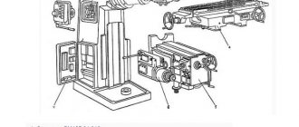
Purpose and scope
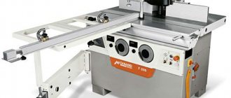
The 6P82 machine has smaller dimensions and requires less working space than the 6P83 variants. It should also be taken into account that the latter produce more engine power. If equipment is required for large-scale production, then preference should be given to 83. But at the same time, 82 has some design features that make it in demand.
The machine table rotates up to 45 degrees in both directions. In this case, the plane rotates about the vertical axis. Features allow you to work on metal in any conditions and carry out thorough processing of even hard-to-reach sides of the workpiece.
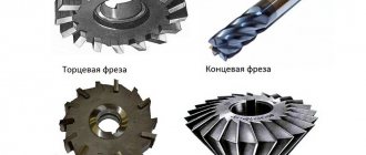
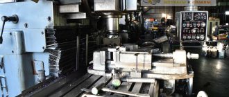
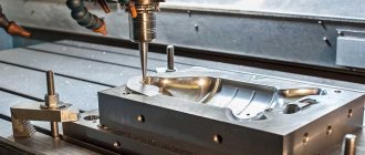
The scope of application of the horizontal machine is large-scale. It is used to work with workpieces made of non-ferrous metals, steel and cast iron - there is no difference, but you need to select the right cutters. The milling machine carries out processing with various types of cutters, including cylindrical disk, angular, end, ring, and end cutters. Conveniently, you can buy additional parts and carry out the work on the blanks yourself, outside of mass production.
The horizontal milling machine is most in demand in mass production conditions. The fact is that it can be set to an automatic or semi-automatic operating cycle. This means that the parts will be processed automatically, without requiring human intervention or control. Features greatly simplify operational activities, making them safe and fast.
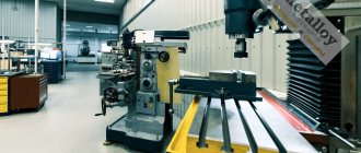
The shape of the planes with which the equipment is worked is not limited. Various vertical and horizontal variations are used. You can easily work cogwheels, grooves, frames or corners. Therefore, a machine type 6P82 and 83 is considered one of the best options for mass production, which requires large capacities, but at the same time requires equipment with diverse cutters.
An additional plus is that the functionality of the machine is expanded with the help of a round table; you can also purchase a dividing or overhead head, which expands the range of possibilities.
Description of the operation of the electrical circuit of cantilever milling machines
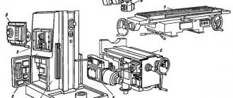
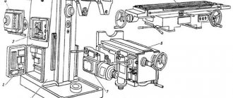
The electrical circuit (Fig. 1, 2) allows you to operate the machine in the following modes:
- control from handles and control buttons
- automatic control of longitudinal table movements
- mode - round table
The operating mode is selected using switch S6.
When the machine is operated from the handles and the spindle is not rotating, it is necessary to set switch S2 (S4) to the zero position.
ATTENTION! BEFORE DISCONNECTING THE MACHINE FROM THE NETWORK OR PERFORMING REVERSE WHEN THE ELECTRIC SPINDLE MOTOR IS RUNNING, IT IS NECESSARY TO TURN OFF THE ELECTRIC MOTOR WITH THE STOP BUTTON
To make it easier to switch spindle and feed speeds, the machine provides pulse activation of the spindle electric motor with the S9 button, and the feed electric motor with the S14 limit switch. When you press the S9 button, the spindle contactor K4 is turned on in the voltage relay K1, n.o. the contacts of which include a short-circuit relay, the latter through its n.o. the contact becomes self-powered, and n.z. the contact breaks the power supply circuit of contactor K4.
When controlled by handles, the operation of the electrical circuit is ensured by closing the contacts of the corresponding limit switches and buttons.
Switching on and off of the feed electric motor is carried out from the handles acting on the limit switches for longitudinal feed (S17, S19), vertical in transverse feed (S16, S15).
The spindle is turned on and off respectively using the “Start” buttons - S10, S11; "Stop" - S7, S8. When you press the “Stop” button, simultaneously with the spindle motor turning off, the feed motor is also turned off.
The table moves quickly when you press the “Fast” button S12 (S13), which turns on the high speed electromagnet Y1 using contactor K3.
The braking of the spindle electric motor is electrodynamic. When buttons S7 or S8 are pressed, contactor K2 is turned on, which connects the motor winding to a DC source made using rectifiers Y1. Relay K1 serves to protect selenium rectifiers from breakdown by high voltage when the electric motor is turned off.
When working on one of the feeds, the possibility of accidentally turning on another feed is eliminated: blocking is carried out by limit switches S15-S19. For automatic control, switch S6 must be set to the “Automatic cycle” position. In addition, it is necessary to mechanically switch the roller located in the machine slide to the “Automatic cycle” position. At the last position of the shaft, the longitudinal stroke clutch is locked and the limit switch S20 is pressed.
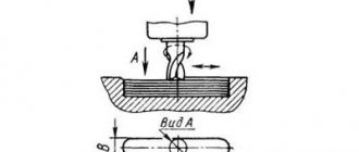
Automatic control is carried out using cams installed on the table. When the table moves, the cams, acting on the handle for turning on the longitudinal feed into the upper sprocket (Fig. 3), make the necessary switches in the electrical circuit using limit switches S17, S19, S18. Limit switch S20 eliminates the possibility of switching on transverse and vertical feeds in this operating mode.
For a description of the operation of the handles and sprockets acting on the limit switches, as well as the settings of the cams, see the operating instructions, part I.
The operation of the electrical circuit in the automatic cycle - fast approach - working feed - quick withdrawal - occurs as follows: when the longitudinal feed handle is turned off, the rod acting on the limit switch S18 should be in the deep cavity of the lower sprocket. Contacts 41-17 of limit switch S18 must be closed. When the longitudinal stroke handle is turned on to the right, the table quickly moves to the right. The high speed is switched off at the desired point by acting on the top sprocket with a cam, which, when turned, opens both contacts of the limit switch S18. The table continues to move at the working feed. When the cams act on the handle in the sprocket, the feed is reversed and high speed is activated to the left. When the handle passes through the neutral position, power is supplied to the contactor K5 through contacts 35-43 of the limit switch S18. The rod acting on the limit switch must at this moment be in the area of constant curvature of the lower sprocket.
The high speed to the left is turned off at the end of the cycle by moving the handle with the cam to the neutral position. The machine operates on other cycles by adjusting the corresponding cams. The operation of the electrical circuit in this case is similar.
When working with a round table, switch S6 is set to the “Round table” position. In this case, the inclusion of longitudinal, transverse and vertical feeds is excluded. The blocking is carried out by limit switches S14-S20.
The rotation of the round table is carried out from the feed motor, which is started by the K6 contactor simultaneously with the spindle motor.
The rapid movement of the round table occurs when the “Fast” button is pressed, turning on the contactor K3 of the high-speed electromagnet.
Schedule and composition of repair and maintenance work
When the machine operates under normal operating conditions and compliance with all operating and maintenance rules specified in this manual, the overhaul cycle (service life before major repairs during two-shift operation) is (mainly) at least 9 years when processing steel (mainly), and at least 8 years for cast iron years.
Maintenance and repair work is recommended to be carried out according to the repair work schedule (Fig. 39).
| Parameter name | 6Р82 | 6R82G | 6Р83 | 6R83G |
| Cutter diameter, mm | 100 | 100 | 100 | 100 |
| Number of teeth | 8 | 8 | 8 | 8 |
| Milling width, mm | 100 | 100 | 150 | 150 |
| Milling depth, mm | 12 | 12 | 10 | 10 |
| Number of revolutions per minute, rpm | 50 | 50 | 50 | 50 |
| Longitudinal feed along the dial, mm/min | 125 | 125 | 125 | 125 |
In these modes, the clutch may periodically click.
The gap between the clutch discs is adjusted using nut 14, which is secured against spontaneous movement.
Schedule and composition of repair and maintenance work
When the machine operates under normal operating conditions and compliance with all operating and maintenance rules specified in this manual, the overhaul cycle (service life before major repairs during two-shift operation) is (mainly) at least 9 years when processing steel (mainly), and at least 8 years for cast iron years.
Maintenance and repair work is recommended to be carried out according to the repair work schedule (Fig. 39).
Machine inspection
- External inspection of the machine (without disassembling to identify defects) of the condition and operation of the machine as a whole and by components;
- Inspection and check of the condition of the main movement and feed drive mechanisms;
- Adjusting the table lead screw clearances;
- Spindle bearing adjustment;
- Checking the operation of speed and feed switching mechanisms;
- Regulation of the mechanisms for switching on cam clutches and feeds and the high-speed friction clutch;
- Adjustment of table wedges, slides, console and trunk;
- Inspection of guides, cleaning of nicks and burrs;
- Tightening loose fasteners;
- Checking the operation of the limiting cams;
- Checking the condition and minor repairs of cooling and lubrication systems;
- Checking the condition and repairing protective devices;
- Identification of parts that require replacement during the next repair (starting with the second minor repair);
Small machine repair
- Partial disassembly of components;
- Flushing all components;
- Adjustment or replacement of rolling bearings;
- Cleaning burrs and nicks on gear teeth, crackers and shift forks;
- Replacement and addition of friction discs of the high-speed clutch (starting from the second repair);
- Scraping and cleaning of wedges and strips;
- Cleaning the lead screws and replacing worn nuts;
- Cleaning nicks and burrs on the guides and working surface of the table;
- Replacing worn and broken fasteners
- Checking and adjusting the mechanisms for switching on speeds and feeds;
- Repair of lubrication and cooling systems;
- Testing the machine at idle speed, checking for noise, heating and accuracy of the workpiece.
Average machine repair
- Unit disassembly of the machine;
- Flushing all components;
- Inspection of parts of disassembled units;
- Drawing up a list of defects;
- Adjusting or replacing spindle bearings;
- Replacement or restoration of spline shafts;
- Replacement of worn bushings and bearings;
- Replacement of discs and fastener clutch parts;
- Replacement of worn gears;
- Restoring or replacing worn lead screws and nuts;
- Scraping or replacing adjusting wedges;
- Repair of pumps and fittings of lubrication and cooling systems;
- Correction by scraping or grinding the surfaces of the guides if their wear exceeds the permissible level;
- Painting the external surfaces of the machine;
- Running in the machine at idle (at all speeds and feeds) with checking for noise and heating;
- Checking the machine for accuracy and rigidity according to GOST 17734-72.
Overhaul of the machine
Major repairs are carried out with complete disassembly of all components of the machine, based on the results of which a defective estimate sheet must be drawn up. As a result of the repair, all worn components and parts of the machine must be restored or replaced, and its original accuracy, rigidity and power must be restored. The nature and scope of work for this type of repair are determined for specific operating conditions by a unified system of scheduled preventive maintenance.
List of elements of the electrical circuit diagram of cantilever milling machines
List of elements of the electrical circuit diagram of a cantilever milling machine
List of elements of the electrical circuit diagram of a cantilever milling machine
Basic requirements for an electric drive.
One of the main issues of electrical equipment is the choice of the type of electrical wire, the basic requirements for electrical wires:
1. Speed control range
2. Smooth speed control over a wide range
3. Cost-effective speed control due to the use of starting and control rheostats
4. Smooth transition of adjustable speed from nominal speed, both to the upper and lower positions
5. Economic indicator of electrical wire operation: high efficiency and power factor (cos φ)
6. Reliability, simplicity, maintenance and setup
7. The choice of electric drive depends on the nature of the load, the frequency of switching on, the ratio of periods of machine and auxiliary time
8. The mechanical characteristics of the electrical wire must be rigid
9. The period of angular velocity when the load on the motor shaft changes from idle to rated speed should not exceed S÷10%
This machine meets the following requirements: The speed control range for forward rotation is 30-3125 rpm.
Engine efficiency - 87.5%; сos φ - 0.85.
The period of angular velocity when the load on the motor shaft changes from idle to nominal does not exceed 10%.
List of graphic symbols on a cantilever milling machine
List of graphic symbols on a cantilever milling machine
List of graphic symbols on a cantilever milling machine
List of graphic symbols on a cantilever milling machine
Description of electrical equipment of milling machines. Video.
- Cantilever milling machines 6Р82, 6Р83, 6Р82Г, 6Р83Г, 6Р82Ш, 6Р83Ш, 6Р12, 6Р13, 6Р12Б, 6Р13Б. Operating manual for electrical equipment 6Р82.ЭО.000 РЭ1,
- Ignatov V.A. Electrical equipment of modern metal-cutting machines and processing complexes, 1991
- Komarov A.F. Adjustment and operation of electrical equipment of metal-cutting machines, 1975
- Rozman Design, adjustment and operation of electric drives of metal-cutting machines, 1985
- Chernov E.A. Complete electric drives for CNC machines, 1989
- Kharizomenov I.V. Electrical equipment of metal-cutting machines, 1958
Bibliography:
Related Links. Additional Information
- Milling machines: general information, classification, designation
- Comparative characteristics of cantilever milling machines of the 6N, 6M, 6R, 6T
- Feed box for console milling machines of the 6M : 6M12P, 6M13P, 6M82, 6M83, 6M82Sh, 6M83Sh
- Feed box for console milling machines of the 6P : 6P12, 6P13, 6P82, 6P83, 6P82Sh, 6P83Sh
- Feed box for console milling machines 6T : 6T12, 6T13, 6T82, 6T83, 6T82Sh, 6T83Sh
- Milling machine repair technology
- Adjustment of milling machines
- Friction clutch. Friction shaft. Friction clutches in metal-cutting machines
- Automatic cycles of milling machines (6P12)
- Testing and checking metal-cutting machines for accuracy
- Directory of universal milling machines
- Manufacturers of metal-cutting machines in Russia
- Manufacturers of milling machines in Russia
- Electrical equipment of milling machines 6T12, 6T13, 6T82, 6T82G, 6T82Sh, 6T83, 6T83G, 6T83Sh
- Electrical equipment of milling machines 6P12, 6P13, 6Р82, 6Р82Г, 6Р82Ш, 6Р83, 6Р83Г, 6Р83Ш, 6Р12Б, 6Р13Б
- Electrical equipment of milling machines 6M12P, 6M12PB, 6M13P, 6M13PB, 6M82, 6M82Sh, 6M82GB, 6M83, 6M83Sh
- Electrical equipment of milling machines 6T10, 6T80, 6T80G, 6T80Sh
- Electrical equipment of milling machines 6Р10, 6Р80, 6Р80Г, 6Р80Ш
- Electrical equipment of milling machines 6N10, 6N80, 6N80G, 6N80Sh
Electrical equipment of milling machines of the Gorky Machine Tool Plant, GZFS
Electrical equipment of milling machines of the Vilnius Zalgiris Machine Tool Plant
Selection and justification of the applied electrical circuit.
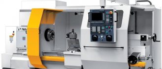
Let's analyze the characteristics and compare two milling machines FA 5A-U and 6P 82.
Characteristics of the FA 5A-U machine.
This machine is designed for a wide range of operations on medium-sized parts for individual and mass production.
The machine can adjust the speed, as well as a wide range of feed speeds, which makes it possible to process all types of materials on the machine, from hard alloy steels to light alloys, with favorable cutting parameters.
Please note that on this machine, due to the high spindle speed limit and high feed rates, it is possible to economically use not only tools with carbide plates, which is also possible by the rigid design of the machine itself.
The universal use of the FA 5A milling machine is significantly expanded by special accessories. By using additional milling heads, dividing devices and rotary tables, the machine can mill straight and helical grooves on cylindrical and conical surfaces, teeth on cylindrical wheels and racks, spiral cams, circular grooves, and also drill cylindrical holes.
The operating capabilities of the machine can be further expanded by using a device for down milling or a device for an automatic cycle.
Technical characteristics of the equipment
The universal milling machine model FA 5A is produced for a three-phase voltage of 380V with a frequency of 50Hz.
The following voltages and alternating currents are used on this machine:
- power circuit 3-50 Hz, 60 Hz, - 220, 380, 400, 415, 440V;
— control circuit 50 Hz, 60 -110 or 220V;
- local lighting circuit 50 Hz - 36, 24 or 110V;
- electrodynamic braking circuit - 56-60V (for a 380-440V network) and 36V (for a 220V network).
Basic parameters of electric motors.
Main drive electric motor (denoted M1 in the diagram). Type AP 644/4 N 5. Power 15 kW. Rotation speed at 50Hz 1455 rpm.
Table feed motor (denoted M2 in the diagram).
Type AR 344/4 N 7. Power 2.2 kW. Rotation speed at 50Hz 1430 rpm.
Electric cooling pump (indicated as MZ in the diagram). SOA type 4-12. Power 0.15 kW. Rotation speed at 50Hz 2800 rpm.
Lubrication pump (indicated in the diagram as M4). PPP type 1. Power 0.067 kW. Rotation speed at 50Hz 1400 rpm.
Characteristics of the machine 6P 83.
The wide-angle cantilever milling machine 6P 83 is designed to perform various milling jobs in individual production conditions.
The machine can produce metal models, dies, molds, templates, cams, etc.
For processing various types of surfaces, as well as large-sized parts exceeding the size of the table, the spindle head is mounted on a retractable trunk and can be rotated at any angle in two mutually perpendicular planes.
The horizontal spindle of the machine can be used when processing planes with face and cylindrical cutters. Both separate and simultaneous operation of both spindles is possible. When installing earrings, the machines can be used as usual horizontally: milling machines.
The technological capabilities of the machine can be expanded with the use of a dividing head, a round rotary table and other devices.
The technical characteristics and rigidity of the machines allow full use of the capabilities of high-speed carbide tools.
The advantages of this machine listed above allow us to give them preference when choosing equipment for the workshop.