Setting up the dividing head
Tutorial
2006
- Gear Cutter Handbook - Page 8
FEDERAL AGENCY FOR EDUCATION
Ozersk Technological Institute
(branch)
STATE EDUCATIONAL INSTITUTION OF HIGHER PROFESSIONAL EDUCATION
"Moscow Engineering Physics Institute
(State University)"
Design Features
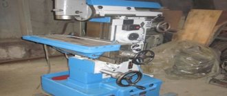
The dividing head, which is created for a milling machine, is a horizontal type machine tool that can also be used on jig boring machines. The purpose of this device is to periodically rotate the workpiece. The following points can be highlighted:
- the rotation can be performed at an equal or unequal angle. This indicator is set with high accuracy;
- a dividing head is used for cutting teeth, cavities between teeth, milling polyhedra, grooves and other elements;
- This element can be used to significantly increase the capabilities of the milling machine. Without a special tool, division cannot be carried out with high accuracy;
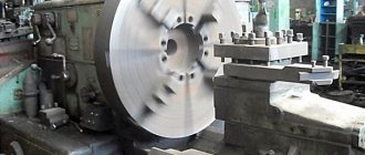
- The workpieces are fastened in a chuck. If the length of the workpiece is large enough, then fastening is carried out using the tailstock. The need for correct positioning of the workpiece with a low probability of deviation from the initial base should be taken into account.
This device has been in use for the past few years.
Projects on the topic:
Search Wiki Archive Children Science Business Work programs Faculties Mathematics
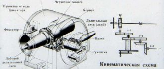
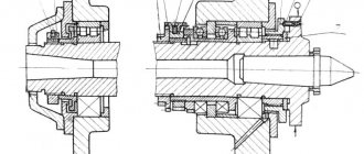
With the help of a dividing head, in which the spindle is driven into rotation by a worm gear, it is possible to perform technological operations of simple division for all kinds of parts that require processing of surfaces with a change in angular position. Such dividing heads have characteristics expressed in the number of revolutions that must be made by the handle in order for the spindle to turn one full revolution.
To calculate the number by which you need to turn the index head handle for the corresponding spindle rotations, use the following formula:
| n= | NZ |
- n – crank revolutions
- N – characteristic of the dividing head
- Z – how many parts should be divided into
If instead of the letter N we put the characteristic of the dividing head, for example 40, we get:
| n= | 40Z |
Main characteristics.
The main characteristic of the dividing head N is the reciprocal of the gear ratio of the worm pair. Technical characteristics of universal dividing heads of the UDG type are presented in Table 1.
Table 1 - Technical characteristics of universal dividing heads
| Characteristic | UDG-160 | UDG-200 | UDG-250 | UDG-320 |
| Largest diameter of the workpiece, mm | 160 | 200 | 250 | 320 |
| Center height, mm | 80 | 100 | 125 | 160 |
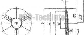
| Mounting flange diameter (size for machine spindle) | 36,541 | 41,275 | 53,975 | 53,975 |
| Key width, mm | 14 | 14 | 18 | 18 |
| Spindle rotation angle from horizontal position | ||||
| — down from the line of centers, degrees | 90 | 95 | 95 | 95 |
| — up from the line of centers, degrees | 6 | 5 | 5 | 5 |
| Worm gear ratio | 1:40 | 1:40 | 1:40 | 1:40 |
| Mounting in spindle hole (Morse taper) | 3 | 3 | 4 | 4 |
| Vernier division price | 10” | 10” | 10” | 10” |
| Replaceable gear module, mm | 1,5 | 1,5 | 1,5 | 1,5 |
| Weight, kg (net) | 36 | 67 | 119 | 125 |
| Weight, kg (gross) | 42 | 79 | 132 | 140 |
| Dimensions | 544×405×222 | 616×465×265 | 536×460×310 | 710×505×342 |
| Maximum load, kg | 80 | 100 | 130 | 130 |
Example 1
Let's say you want to make a flange with eight holes. In order to drill equidistant holes on this product, you can use a dividing head. In this situation, first of all, you need to determine the number of turns of the handle in order to rotate the spindle at certain angles. Since the characteristic of the dividing head is forty, according to the formula, this number must be divided by the number of proposed holes. The result of division will be an integer equal to five.
| n= | 40Z | = | 408 | = 5 |
Knowing the result of the calculation, the flange is fixed in the dividing head chuck and the tool is placed in the position required to begin processing. Next, the first hole is drilled, after which 5 full turns of the handle are made, the next hole is processed, and so on.
Procedure for setting up and using
How to use the dividing head on a milling machine and make transitions? This depends on the model purchased, the scale division price and other characteristics. Current standards are also important: for parts of accuracy class VIII you should be guided by the data of GOST 1.758, for IX - 1.643.
In general, preliminary debugging and preparation for operation comes down to choosing a sector based on the diameter of the circle and the required number of parts. You need to do the following:
- • convert a full cycle (360 degrees) into the required number of steps;
- • calculate the appropriate sine of the angle;
- • rotate the disk by the just found radial value;
- • fix the body with a clamp (or the handle of the unit) and place the main tool in this position.
Typically, manufacturers in their instructions indicate the formula by which the angle of the dividing head is calculated, so let’s see how to work with UDG further, let’s not dwell only on calculations, let’s move on to practice.
So, it is necessary to install the workpiece in the machine’s mandrel and, with longitudinal feed, carry out the desired operation. There is a step to consider, which depends on what kind of task is being performed. For example, when creating teeth, the discrete movement must be equal to the distance between the cavities of adjacent elements.
Productivity can be increased without compromising quality by returning the table to its original position in an accelerated manner. The most reliable way to fix it in the disk hole is with a spring.
Example 2
In order to mill 3 equal sides into a part of a part, it is usually fixed in a dividing head chuck. If necessary, the part can be tightened by the center of the tailstock. And, of course, before starting work, they carry out the necessary calculations.
In this case, if the characteristic of the dividing head is forty, then its value must be divided by three. The result of the division operation is thirteen whole revolutions and another third. The denominator of the resulting fraction indicates the number of holes in the pitch circle. But since there is no disk with three holes, you need to select a circle on the disk whose value will be a multiple of three. These parameters correspond to circles 21, 30, 33, 39, 54. As a basis, we will choose the number of holes that will be most convenient, for example 21. Next, we expand the fraction one third to seven twenty first.
| n= | 40Z | = | 403 | = 13 | 13 | = 13 | 1 × 73 × 7 | = 13 | 721 |
The result of the calculations is the fraction thirteen point seven twenty one, in other words, the handle needs to be turned 13 times and another 7 holes counted from the starting point on a circle with 21 holes.
Types of division
Division using a cutter is carried out in various ways, among which we note:
- Directly performed without the use of an intermediate device. For this purpose, a unit with conventional optical division is used.
- They use a simple one quite often; it uses an immobilized disk. This cutting method is carried out using UDG, which increases the scope of use.
- The combined product is produced using a head.
- The differential method is carried out on conventional dividing heads, which have an additional set of replacement wheels.
- The discrete method is implemented by optical and universal heads, which have a kinematic connection between the handle and the longitudinal feed spindle of the machine.
Example 3
The most common technological operation in milling is the processing of parts to obtain hexagonal surfaces. In order to process six faces, it is necessary to determine the number of revolutions of the dividing head handle so that the spindle as a result rotates at equal angles. To do this, you need to use the calculation formula for simple division.
If you divide forty by six you get six whole numbers and a fractional number of four sixths, which reduces to two thirds. The fraction two thirds then expands to fourteen twenty firsts.
| n= | 40Z | = | 406 | = 6 | 46 | = 6 | 23 | = 6 | 2 × 73 × 7 | = 6 | 1421 |
To turn one side of the hexagon, you need to make 6 full turns and then stop.
Classification of supplies used for corner installation
The process can take place when using the following types of device:
- universal methods of implementation;
- simplified designs;
- optical type, which is used to perform particularly precise activities.
The above classification must be taken into account when discussing designs that enhance the functions of a machine tool. Often division occurs with this unit; universal methods of implementation are used quite often.
Benefits of using UDG
Indispensable for the processing of massive parts by tool, repair and restoration and experimental shops in the conditions of piece production. Application in mass or serial production is costly and, often, technologically not justified.
The device allows:
- milling of surface grooves and edges of any complexity;
- with ensuring accuracy, create edges on workpieces, on nuts with non-standard parameters, on the shanks of cutting tools;
- cut grooves, splines and polyhedrons;
- mill sprockets, as well as hollows between wheel teeth.
Optical head marking
When using a milling machine, optical dividing heads can also be installed. There is a certain formula that allows you to determine the degree of accuracy of the equipment in question. A popular model can be called ODG-5. The decryption in this case looks like this:
- ODH is an abbreviation for the name of the device, which stands for optical dividing head.
- 5 – dc indicator, which is indicated in seconds. The calculation of this indicator is carried out during the production of the equipment in question.
In the production of this equipment, the need to maintain precise dimensions is taken into account, since even a slight deviation can lead to large discrepancies in dimensions. The calculation is carried out using modern methods.
Table of contents
It’s no secret to milling specialists how to use a dividing head, but many people don’t even know what it is. It is a horizontal machine tool that is used on jig boring and milling machines. Its main purpose is to periodically rotate the workpiece, during which division into equal parts occurs. This operation is relevant when cutting teeth, milling, cutting grooves, and so on. With its help you can make gear teeth. This product is often used in tool and machine shops, where it helps to significantly expand the operating range of the machine. The workpiece is secured directly in the chuck, and if it turns out to be too long, then in a steady rest with emphasis on the tailstock.
Types of work performed
The UDG device allows you to provide:
- Precise milling of sprockets, even if the number of teeth and individual sections is several dozen;
- It is also used to produce bolts, nuts and other parts with edges;
- Milling of polyhedra;
- Grooving the depressions located between the teeth of the wheels;
- Grooving of cutting and drilling tools (for which continuous rotation is used to obtain a spiral groove);
- Processing the ends of multifaceted products.