Information about the manufacturer of the 6Р82Ш cantilever milling machine
Manufacturer of the series of universal milling machines 6Р82Ш Gorky Milling Machine Plant , founded in 1931.
The plant specializes in the production of a wide range of universal milling machines, as well as milling machines with DRO and CNC, and is one of the most famous machine-tool enterprises in Russia.
The production of milling machines at the Gorky Machine Tool Plant began in 1932. In 1972, the plant began producing a series of horizontal cantilever milling machines 6Р82Ш and 6Р83Ш, which are a further development of machines of similar models of the M series.
Today the 6Р82Ш cantilever milling machine produces:
- Stanochny Park LLC;
- Machine tool association LLC SO "StanRos".
Products of the Gorky Milling Machine Plant GZFS
- 6M12P
vertical cantilever milling machine 320 x 1250 - 6M13P
vertical cantilever milling machine 400 x 1600 - 6M82
universal horizontal milling machine 320 x 1250 - 6M82G
horizontal cantilever milling machine 320 x 1250 - 6М82Ш
universal cantilever milling machine 320 x 1250 - 6M83
universal horizontal milling machine 400 x 1600 - 6M83G
horizontal cantilever milling machine 400 x 1600 - 6N12
vertical cantilever milling machine 320 x 1250 - 6N13P
vertical cantilever milling machine 400 x 1600 - 6N82
horizontal cantilever milling machine 320 x 1250 - 6N82G
horizontal cantilever milling machine 320 x 1250 - 6Р12, 6Р12Б
vertical cantilever milling machine 320 x 1250 - 6Р13, 6Р13Б
vertical cantilever milling machine 400 x 1600 - 6Р13Ф3
vertical cantilever milling machine with CNC 400 x 1600 - 6Р82
universal horizontal milling machine 320 x 1250 - 6R82G
horizontal cantilever milling machine 320 x 1250 - 6Р82Ш
universal cantilever milling machine 320 x 1250 - 6Р83
universal horizontal milling machine 400 x 1600 - 6R83G
horizontal cantilever milling machine 400 x 1600 - 6Р83Ш
universal cantilever milling machine 400 x 1600 - 6T12-1
vertical cantilever milling machine 320 x 1250 - 6T12
vertical cantilever milling machine vertical 320 x 1250 - 6T12F20
vertical cantilever milling machine with CNC 320 x 1250 - 6T13
vertical cantilever milling machine 400 x 1600 - 6T13F20
vertical cantilever milling machine with CNC 400 x 1600 - 6T13F3
vertical cantilever milling machine with CNC 400 x 1600 - 6T82
universal horizontal milling machine 320 x 1250 - 6T82-1
universal horizontal milling machine 320 x 1250 - 6T82G
horizontal cantilever milling machine 320 x 1250 - 6Т82Ш
universal cantilever milling machine 320 x 1250 - 6T83
universal horizontal milling machine 400 x 1600 - 6T83-1
universal horizontal milling machine 400 x 1600 - 6T83G
universal horizontal milling machine 400 x 1600 - 6Т83Ш
universal cantilever milling machine 400 x 1600 - 6606
longitudinal milling machine 630 x 2000 - GF2171
vertical milling machine with CNC and ASI 400 x 1600
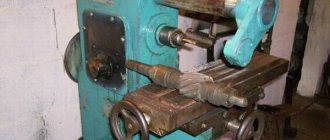
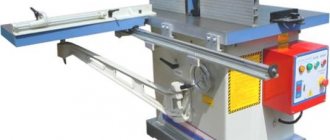
6Р82Ш universal cantilever milling machine. Purpose and scope
6Р82Ш milling machine has been produced since 1972 and replaced the outdated 6М82Ш model in production and was replaced by a more advanced model 6Т82Ш.
Machines of the 6Р83Ш model differ from the 6Р82Ш by the increased size of the work table and a more powerful main movement motor.
The table of the universal cantilever milling machine model 6Р82Ш is non-rotating.
The highly versatile cantilever milling machine 6Р82Ш is designed to perform a variety of milling work, mainly in the manufacture of metal models of stamps and molds for work in serial and individual production.
Operating principle and design features of the machine
The advantage of widely universal milling machines is the ability to process a workpiece from different sides from one installation, which is very important in tool, repair and pilot production, where installation, alignment and fastening of the workpiece takes a lot of time and requires highly qualified workers.
To process various types of surfaces, as well as large-sized models that exceed the dimensions of the table, the spindle head is mounted on a retractable trunk and can be rotated at an angle in two mutually perpendicular planes.
6Р82Ш machine is equipped with a horizontal spindle, which can be used when processing planes with end and cylindrical cutters.
Both separate and simultaneous operation of two spindles is provided. When installing the earrings supplied with the machine, the machine can be used as a horizontal milling machine.
To expand the capabilities of the machine, in addition to the earrings, an additional overhead rotating head is included. The overhead head allows you to process large parts, as well as perform simple boring work.
The presence of a backlash sampling mechanism in the screw pair of the longitudinal feed of the table allows for up and down milling both in simple modes and in modes with automatic cycles.
Milling of gears, reamers, cam contours and other parts that require periodic or continuous rotation around their axis is carried out on these machines using a dividing head or an overhead round table.
Lubrication of the console guides and the table-slide assembly is carried out centrally from a plunger pump. Thanks to effective lubrication, the durability of these components increases, the original accuracy is maintained longer and maintenance time is reduced. The roughness of the treated surface is Rz 20 µm. Machine accuracy class P.
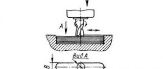
6Р82Ш machine is designed for milling all kinds of parts made of steel, cast iron and non-ferrous metals using cylindrical, disk, shaped, corner, face, end and other cutters. The ability to configure the machine for various semi-automatic and automatic cycles allows you to successfully use the machines to perform operational work in production and automatic lines in large-scale production.
The machine can process vertical and universal planes, grooves, corners, frames, gears, etc.
The technological capabilities of the machine can be expanded with the use of a dividing head, a rotary round table, an overhead universal head and other devices.
The design features of the machine are:
- wide ranges of table feed values;
- quick-change tool mount;
- presence of a feed slowdown mechanism;
- slowing down the working feed in the automatic cycle;
- ability to work in automatic cycles, including frame processing;
- automatic lubrication of components;
- the use of non-contact high-speed electromagnetic clutches in the feed drive;
- increased accuracy of the machine due to the location of the cross-feed screw along the axis of the cutter;
- the ability to move the table simultaneously in two and three coordinates;
- the possibility of using a DC electric motor in the feed drive;
- possible further automation of machines through the use of digital display and operational control devices;
6Р82Ш machines are designed to perform various milling operations in both individual and large-scale production. In conditions of large-scale production, machines can also be successfully used to perform operational work.
The technical characteristics and high rigidity of the machines allow full use of the capabilities of both high-speed and carbide tools.
To reduce auxiliary time and ease of control, the machines provide:
- duplicated push-button-handle control (front and left side of the machine)
- starting and stopping the spindle and turning on the high speeds of the machine using buttons
- control of table movements from handles, the direction of rotation of which coincides with the direction of movement of the table
- changing speeds and feeds using single-handle selective mechanisms, allowing you to obtain any speed or feed by turning the dial without going through intermediate steps
- DC braking
The machines are automated and can be configured for various automatic cycles, which increases labor productivity, eliminates the need to maintain the machines by highly qualified workers and facilitates the possibility of organizing multi-machine maintenance.
Machine accuracy class P according to GOST 8-77.
History of production of machine tools by the Gorky plant, GZFS
In 1937
, the Gorky
Milling Machine Plant produced the first cantilever milling machines of the 6B series, models 6B12 and 6B82 , with a work table of 320 x 1250 mm (2nd standard size).
In 1951
6N of cantilever milling machines was launched into production 6N13PR machine received the “Grand Prix” at the world exhibition in Brussels in 1956.
In 1960
6M cantilever milling machines
was launched into production In 1972
6P of cantilever milling machines
was put into production In 1975
year, copying cantilever-milling machines were launched into production:
6Р13К .
In 1978
In 2009, copying cantilever-milling machines
6Р12К-1 , 6Р82К-1 .
In 1985
6T-1 of cantilever milling machines
was put into production In 1991
6T of cantilever milling machines was put into production
Design features
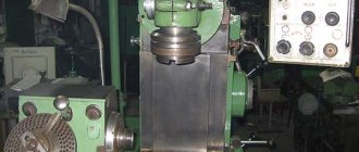
Appearance
Milling and processing equipment of the 6Р82Ш brand was developed and produced at the Gorky Milling Machine Plant. This enterprise is the oldest and, thanks to the accumulated experience, the machines manufactured there are characterized by good operational and technical parameters.
A feature of the widely-universal milling equipment is the ability to simultaneously process the workpiece on both sides. This allows you to increase productivity, since you do not need to change the position of the workpiece on the work table to perform another operation.
Additionally, the following characteristics can be highlighted:
- presence of a horizontal spindle. It can be used to perform machining with cylindrical and end mills;
- additional earring adapters. After their installation, it becomes possible to perform horizontal milling operations;
- rotating overhead head. With its help, large parts are processed and boring work is performed;
- possibility of installing an overhead table and dividing head.
To automate the production process, you can choose manual, semi-automatic or automatic operating mode. Quick replacement of the cutter is carried out using a quick-change mechanism. Also, the 6Р82Ш machine has a wide range of work table offsets.
The working head quickly stops due to DC braking. This increases productivity because it takes less time to change cutting tools.
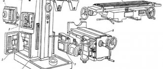
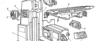
Location of components on the 6Р82Ш machine
Location of components on the 6r82sh machine
List of components of the 6Р82Ш milling machine
- Bed - 6Р82Ш-1
- Trunk - 6Р82Ш-11
- Gearbox - 6М82-3
- Feedbox - 6Р82-4
- Switching box - 6Р82-5
- Console - 6Р82-6
- Table and slide - 6Р82Г-7
- Electrical equipment - 6Р82Ш-8
- Overhead head - 6Р82Ш-32
- Rotating head - 6Р82Ш-31
List of graphic symbols on a cantilever milling machine
List of graphic symbols on a cantilever milling machine
List of graphic symbols on a cantilever milling machine
List of graphic symbols on a cantilever milling machine
Location of controls for the 6Р82Ш milling machine
Location of controls for milling machine 6р82ш
List of controls for the 6Р82Ш milling machine
- Stop button (duplicate)
- “Spindle Start” button (duplicate)
- Arrow - spindle speed indicator
- Spindle speed indicator
- “Quick table” button (duplicate)
- "Spindle pulse" button
- Light switch
- Manual movement of the trunk
- Rotary head spindle speed shift knob
- Earring clips
- Swivel head clamp
- Spindle sleeve extension handwheel
- Spindle sleeve clamp handle
- Handle for turning on longitudinal table movements
- Automatic cycle sprocket
- Table Clamps
- Handwheel for manual longitudinal movement of the table
- “Quick table” button
- Spindle start button
- Stop button
- Switch for manual or automatic table control
- Handwheel for manual lateral movements
- Limb of the table transverse movement mechanism
- Vernier ring
- Handle for manual vertical movements
- Button for fixing the feed switch fungus
- Feed switch mushroom
- Table feed indicator
- Table feed indicator arrow
- Handle for turning on the transverse and vertical table feeds
- Clamping the slide on the console guides
- Handle for turning on longitudinal movements of the table (duplicate)
- Handle for turning on the transverse and vertical table feed (duplicate)
- Input switch "On - Off"
- Cooling pump switch “On - Off”
- Horizontal spindle rotation switch “Left - Right”
- Handwheel for manual longitudinal movement of the table (duplicate)
- Horizontal spindle speed shift knob
- Reversible switch for the direction of rotation of the spindle of the overhead head
- Control switch “Automatic cycle - Manual control - Round table operation”
- Clamping the console on the frame
- Trunk clamp on the frame
Main advantages of the machine:
Constructive:
- mechanized tool fastening in the spindle;
- a device for periodically adjusting the size of the gap in the longitudinal feed screw pair;
- safety clutch protecting the feed drive from overloads;
- spindle braking when stopping using an electromagnetic clutch.
- various automatic machine operation cycles;
- wide range of spindle speeds and table feeds;
- high drive power;
- high rigidity;
- reliability and durability
Technological:
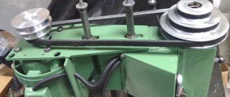
Kinematic diagram of the 6Р82Ш milling machine
Kinematic diagram of the milling machine 6р82ш
The gearbox allows you to select the required speed without sequentially passing through intermediate stages.
Rack 19 (Fig. 10), moved by shift handle 18, by means of sector 15 through fork 22 (Fig. 11) moves the main roller 29 with shift disk 21 in the axial direction. The shift disk can be turned with the speed indicator 23 through bevel gears 28 and 30. The disk has several rows of a certain size of holes located against the pins of the racks 31 and 33. The racks engage in pairs with a gear 32. A shift fork is attached to one of each pair of racks. When moving the disk by pressing on the pin of one of the pair, reciprocating movement of the slats is ensured.
In this case, the forks at the end of the disk stroke take a position; corresponding to the meshing of certain pairs of gears. To eliminate the possibility of hard stop of the gears when switching, the pins of 20 racks are spring-loaded.
Fixation of the dial when choosing a speed is ensured by ball 27, which slides sprocket 24 into the grooves.
The spring 25 is adjusted by plug 26, taking into account the precise fixation of the dial and the force when turning it.
Handle 18 (see Fig. 10) is held in the on position by spring 17 and ball 16. In this case, the handle tenon fits into the groove of the flange.
Correspondence of speeds to the values indicated on the indicator is achieved by a certain position of the bevel wheels 28 and 30 (see Fig. 11) along the mesh. Correct engagement is established by cores at the ends of the mating tooth and cavity or by setting the pointer to the speed position of 31.5 rpm and the disk with forks to the speed position of 31.5 rpm. The gap in the engagement of the conical pair should not be more than 0.2 mm, since the disk can rotate up to 1 mm due to this.
The gearbox is lubricated by the gearbox lubrication system by spraying oil coming from a tube at the top of the frame. Lack of oil rain can cause unacceptable heating of the shift fork jaws and lead to fork binding, deformation or failure.
The connector plane is sealed with a gasket or gasoline-resistant grease. GOST 7171-63.
Kinematic diagram
The sequence of movements of all parts of the drive of the 6Р82Ш milling machine is determined by the interaction of its main components. The main working movements are the movement of the tool head with spindles and the table feed movement. The feedbox of a machine is characterized by a certain combination of rotation speed steps (18 in total). In this case, the lowest rotation speed is 0.52 s-1, and the highest is 26.6 s-1. In turn, the machine spindles are driven by their own electric motor using gears. The number of speeds is 12, with the lowest and highest speeds being 0.83 s-1 and 26.6 s-1, respectively.
A separate branch of the kinematic diagram is the drive of the table movement mechanism in the transverse and longitudinal directions. The movement from a separate electric motor is transmitted through the clutch to gears. Due to the presence of different combinations of gear pairs, the range of possible horizontal feed speeds is from 25 to 2500 mm/min. Rapid feed is also possible - 3000 mm/min. In the vertical direction, the highest feed speed is 416 mm/min, and the lowest is 8.3 mm/min, with a feed speed in the installation (adjustment) mode of 1000 mm/min.
The kinematic diagram of the machine provides for electromechanical blocking from the simultaneous activation of several feeds of the work table.
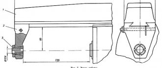
Main components and mechanisms of the 6Р82Ш milling machine
The trunk 5, in which the gearbox of the spindle drive of the rotary head 6 is mounted, moves along the guides of the frame 1 (Fig. 121) by rotating the flywheel 15 (Fig. 120) with the clamp 39 released.
Gearbox for console milling machine 6р82ш
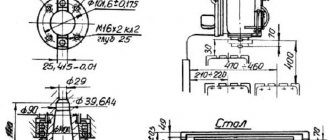
Spindle 11 of the machine (Fig. 123) is mounted on bearings 4, 2, 12. The axial clearance in the spindle is adjusted by grinding rings 9,10. Increased clearance in bearing 4 is eliminated by grinding half rings 5 and nut 1 as follows. Remove cover 3 (or side cover), flange 6, spring ring 7, rings 8 and take out half rings 5. Using nut 1, select the gap so that during operation the heating of the bearings does not exceed 60 ° C. Measure the size of the gap between the bearing and the spindle collar and Accordingly, the half rings 5 are polished. Then the half rings are installed and parts 6, 8, 7, 3 are mounted.
The gearbox (Fig. 124) allows you to select the required speed without sequentially passing through intermediate stages. Rack 1 (Fig. 124, a), moving by means of a handle through gear sector 2 and fork 10 (Fig. 124, 6), moves the main roller 3 with shift disc 9 in the axial direction using gear 2 and bushing 4. On the disc There are several rows of holes located opposite pins 8 of racks 5 and 7, connected in pairs to wheel 6. A shift fork is attached to one of each pair of racks. The slats move when the disk is pressed on the pins. At the end of the disk stroke, the forks occupy a position corresponding to the engagement of certain pairs of gears. When selecting speeds, the dial is fixed by ball 1 (Fig. 124, b), which falls into the grooves of sprocket 11. Handle 5 (Fig. 124, a) is fixed when turned on by ball 3 and spring 4; in this case, the handle tenon fits into the groove of the flange.
The horizontal spindle gearbox is located in the frame and connected to the electric motor shaft by an elastic coupling.
Rotating head of the cantilever milling machine 6р82ш
The rotating head (Fig. 125) is mounted on the trunk through the intermediate plate using bolts inserted into the annular T-shaped groove and centered in the annular recess. The spindle 8, mounted in the sliding sleeve 9, receives rotation from the gearbox through the cam clutch 1 and conical wheels 4, 2 and 5, 4. Wheels 7 and 3 are used to adjust the axial clearance in the bearings and spindle, and half rings 2 and nut 6 - to eliminate the gap in the front bearing. The sleeve is advanced using a handwheel.
The overhead head (Fig. 126) is mounted on the rotary head with bolts entering the T-shaped groove and firmly fixed. Spindle 5 receives rotation from spindle 1 of the rotary head through bevel gears 3, 4. Nut 2 adjusts the clearance in the spindle bearings.
Feed box for cantilever milling machine 6р82ш
The feed box (Fig. 127, a) provides working feeds and installation movements of the table, slide and console by switching gear blocks and transmitting rotation to input shaft B through a ball safety clutch, cam clutch 4 and bushing 3, connected by a key to clutch 4 and shaft B. Stopper 1 rigidly fixes the position of nut 15. When the feed mechanism is overloaded, the balls in contact with the hole of clutch 2 compress the springs and come out of contact. In this case, wheel 14 slips relative to clutch 2, and the working feed stops.
Rapid rotation is transmitted from the electric motor (bypassing the gearbox) to gear C, which is installed on the shank of the friction clutch housing 9 and has a constant rotation speed. Nut 10 must be tightened. Housing 9 rotates freely. The friction disks are connected (one by one) to the housing 9 and the sleeve 12 connected to shaft B. When the clutch 4 is pressed onto the end of the sleeve 5 and then onto the nut 11, the disks 7 and 8 are connected and transmit rapid rotation to shaft B and gear A. Compression force disks 7 and 8 are adjusted using pin 6. Movement from shaft B to the driven shaft is carried out through a cam clutch 13.
The feed switching mechanism (Fig. 127, b) is included in the feed box assembly. The principle of operation of the mechanism is similar to the operation of a gearbox. When turned on, roller 1 is locked by balls 6 and bushing 2, which prevents disk 9 from moving in the axial direction. When you press button 4, the balls fall into the annular groove of roller 3 and roller 1 is released from fixation. Shift disk 9 is secured against rotation by ball 8 through bushing 5, connected by a key to ball 1. Screw 7 adjusts the spring tension.
Console of cantilever milling machine 6Р82Ш
The console (Fig. 128) combines the nodes of the machine feed chain. It contains shafts and gears that transmit movement from the feed box in three directions (to the longitudinal, transverse and vertical feed screws); mechanism for switching on transverse and vertical feeds. Gear 8 rotates from wheel A (Fig. 127, a) and transmits movement to gears 7, 4, 2, 1 (Fig. 128, a). Wheel 8 can transmit movement to the shaft only through cam coupling 6. Then, through cylindrical and bevel gears, the movement is transmitted to screw 16 (Fig. 128, b). The engagement of the pair 16 and 10 is adjusted by compensators 14, 15 and fixed with a screw inserted into pin 13. Bushing 11 is not dismantled; the vertical movement nut is fixed in the column. Wheel 2 rotates the shaft IX of the longitudinal chain through a key and splines. The cross feed screw X rotates from wheel 2 and wheel 1, which is freely seated on the shaft, when the cross feed clutch is engaged. Shafts XII and XIII are dismantled when removing the stoppers at wheels 8, 9.
Mechanism for switching on installation movements of the 6р82ш milling machine
The slide is dismantled after removing shaft IX, for which you need to remove the upper shield on the console guides, knock out pin 3 and remove shaft IX. The mechanism for activating the installation movements (Fig. 129) turns on the clutch and compresses the friction clutch discs. Lever 1 is pinned on axis 4. The latter is pressed in the direction of the frame mirror by spring 6. The right nuts 2 serve to adjust the spring force, the left nuts 3, resting against the end of the sleeve 5, regulate and limit the stroke of the axis. The shoulder of lever 1 rests on cam 7. Lever 1, when turning cam 7, moves, compressing spring 6. The second end of axis 8 has a fine tooth, which ensures the installation of lever 9, which connects axis 8 at a slight angle to the electromagnet rod. The latter is connected through a rod and a hinge to a fork, from which, through a nut and a spring, the force is transmitted to lever 9. Thus, regardless of the force of the electromagnet, the force on the lever is determined by the degree of compression of the spring.
The mechanism for switching on the transverse and vertical feeds (Fig. 130) controls the switching on and off of the cam clutches of the transverse and vertical feeds from the feed electric motor. Made in a separate building. When the handle 5 moves up, down, left, right, the drum 1 associated with it makes the corresponding movements and, with its bevels, through the lever system controls the activation of the cam clutches, and through the pins - the limit switches intended for reversing the feed motor. The drum is connected by rod 2 with a backup handle. When the transverse stroke is turned on and off, the rod moves translationally, and when the vertical stroke is turned on, it rotates. Screw 4 and nut 3 are used to eliminate gaps in the system.
The lead screw 1 (Fig. 131) of the table receives rotation through the sliding key of the sleeve 9, located in the bushings 5, 7. The sleeve 9 rotates from the cam coupling 6 through the splines when it engages with the cams of the sleeve 5, connected to the bevel gear 4. On the sleeve 5 there is a gear ring, which is in mesh with the gear wheel of the round table drive. Clutch 6 has a toothed ring for rotating the longitudinal feed screw from the handwheel. The slide is clamped to the guide console by faceplate 8. Wheel 9 (Fig. 132) is spring-loaded in case of tooth contact with tooth. Engagement of the wheels is only possible when coupling 6 and bushing 5 are disconnected. This blocks the flywheel during mechanical feeds. Nuts 2 and 3 of the lead screw (Fig. 131) are located on the left side of the slide. The gap in the console and slide guides is selected using wedges.
Mechanism for switching on longitudinal feed of milling machine 6р82ш
The mechanism for turning on the longitudinal feed (Fig. 132) turns on the longitudinal stroke clutch, turns on and reverses the feed motor. Handle 4 is fixedly connected to axis 2 by turning lever 1, along the curved surface of which roller 15 rolls when switching (Fig. 132). In the neutral position of the lever 10, the roller is located in the middle cavity; when it is turned on, it is in one of the side depressions. The movement of roller 15 through lever 16 is transmitted to rod 5 through wheel 7—rack 6 and fork 8 driving clutch 6 (Fig. 131). Spring 2 (Fig. 132) constantly presses on rod 5. Spring 4 ensures that the handle is turned on when a tooth hits the tooth of coupling 6. Spring 4 is adjusted by screw 3 through the hole in plug 1.
On the same axis with the lever 16 there is a lever 18, which serves to engage the clutch 6 with a cam 19 attached to the rod 20 connecting the main longitudinal stroke handle with the backup one. The limit switch 17 turns on and reverses the feed motor. It is turned off after clutch 6 is turned off. On the hub 5 (Fig. 133) of the longitudinal stroke handle there are protrusions that are acted upon by the longitudinal stroke limiting cams or (in automatic cycles) the longitudinal stroke control cams. The operation of the limit switches is checked with cover 14 removed (Fig. 132).
Mechanism of automatic cycle of milling machine 6р82ш
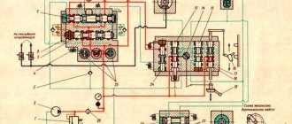
Electrical equipment of the machine 6Р82Ш
Electrical diagram of milling machine 6Р82Ш
Electrical circuit of the milling machine 6р82ш
Notes
- * - only for machines 6Р82Ш, 6Р83Ш
- ** - to the electrical diagram of the tool clamping mechanism
- *** - only for machines 6Р13Б
Location of electrical equipment on the 6Р82Ш milling machine
Supply network: Voltage 380 V, alternating current, frequency 50 Hz
Control circuits: Voltage 110 V, alternating current
Control circuits: Voltage 65 V, DC current
Local lighting: voltage 24 V.
Rated current (sum of rated currents of simultaneously operating electric motors) 20 A.
The rated current of the protective device (fuses, circuit breaker) at the power supply point is 63 A.
Electrical equipment is made according to the following documents: circuit diagram 6Р13.8.000Э3. connection diagram of the product R13.8.000E4.
Technical characteristics of machines models 6Р82Ш
| Parameter name | 6Р82Ш | 6Р83Ш |
| Basic machine parameters | ||
| Accuracy class according to GOST 8-82 | P | P |
| Dimensions of the working surface of the table (length x width), mm | 1250 x 320 | 1600 x 400 |
| The smallest and largest distance from the end of the spindle to the table, mm | 30..450 | 30..450 |
| Distance from the spindle axis to the trunk, mm | 155 | 190 |
| Distance from the end of the rotary head spindle to the table, mm | 35..535 | 70..570 |
| Distance from the axis of the rotary head spindle to the frame guides (extent), mm | 260..820 | 250..900 |
| Desktop | ||
| Maximum table movement longitudinal mechanical/manual, mm | 800/ 800 | 1000/ 1000 |
| Maximum table movement transverse mechanical/manual, mm | 240/ 250 | 300/ 320 |
| Maximum table movement vertical mechanical/manual, mm | 410/ 420 | 410/ 420 |
| Maximum load on the table (center), kg | 250 | 300 |
| Number of T-slots Dimensions of T-slots | 3 | 3 |
| Movement of the table by one dial division (longitudinal, transverse, vertical), mm | 0,05 | 0,05 |
| Table movement per one revolution of the dial, longitudinal and transverse, mm | 6 | 6 |
| Movement of the table per one revolution of the dial, vertical, mm | 2 | 2 |
| Rapid table travel longitudinal/transverse/vertical, mm/min | 3/ 3/ 1 | 3/ 3/ 1 |
| Number of table feed stages | 18 | 18 |
| Working feed limits. Longitudinal and transverse, mm/min | 25…1250 | 25…1250 |
| Working feed limits. Vertical, mm/min | 8,3…416,6 | 8,3…416,6 |
| Cutting force of longitudinal, transverse, vertical feeds, N | 15,0/ 12,0/ 5,0 | 20,0/ 12,0/ 8,0 |
| Spindle | ||
| Spindle rotation speed of rotary and overhead heads, rpm | 50..1600 | 50..1600 |
| Number of spindle speeds | 11 | 11 |
| Spindle speed, rpm | 31,5..1600 | 31,5..1600 |
| Number of spindle speeds | 18 | 18 |
| Spindle quill movement, mm | 80 | 80 |
| Movement of the spindle quill by one dial division, mm | 0,1 | 0,1 |
| Movement of the spindle quill per one revolution of the dial, mm | 6 | 6 |
| Rotation of the spindle head to/from the bed, degrees | 45 | 90 |
| Rotation of the spindle head in the longitudinal plane, degrees | 360 | 360 |
| Rotation of the spindle head in the longitudinal plane, degrees | 360 | 360 |
| Maximum torque on the spindle, N.m | 1070 | 1430 |
| Sketch of the end of a horizontal spindle according to GOST 836-72 | 3 | 3 |
| Sketch of the end of the spindle of the rotary head according to GOST 836-72 | 4 | 4 |
| Sketch of the end of the spindle of the overhead head according to GOST 836-72 | 4 | 4 |
| Spindle taper | 50 | 50 |
| Permissible cutter diameter for roughing. Horizontal/vertical spindle, mm | 160/ 100 | 200/ 100 |
| Machine mechanics | ||
| Feed stops (longitudinal, transverse, vertical) | There is | There is |
| Blocking manual and mechanical feed (longitudinal, transverse, vertical) | There is | There is |
| Blocking separate feed switching | There is | There is |
| Automatic intermittent feed Longitudinal | There is | There is |
| Automatic intermittent feed Cross and vertical | No | No |
| Spindle braking | There is | There is |
| Overload protection (clutch) | There is | There is |
| Drive and electrical equipment | ||
| Number of electric motors on the machine | 4 | 4 |
| Main motion drive electric motor, kW | 7,5 | 10 |
| Electric motor for rotary head spindle drive, kW | 2,2 | 3,0 |
| Feed drive electric motor, kW | 2,2 | 3,0 |
| Electric coolant pump, kW | 0,125 | 0,125 |
| Dimensions and weight of the machine | ||
| Machine dimensions (length x width x height), mm | 2470 x 1850 x 1950 | 2680 x 2260 x 2040 |
| Machine weight, kg | 3300 | 4500 |
- Widely universal cantilever milling machines 6Р82Ш, 6Р83Ш. Operating manual 6Р82Ш.00.000 РЭ. Part 1, 1984
- Cantilever milling machines 6Р82, 6Р83, 6Р82Г, 6Р83Г, 6Р82Ш, 6Р83Ш, 6Р12, 6Р13, 6Р12Б, 6Р13Б. Operating manual for electrical equipment 6Р82.ЭО.000 РЭ1,
- Avrutin S.V. Fundamentals of Milling, 1962
- Avrutin S.V. Milling, 1963
- Acherkan N.S. Metal-cutting machines, Volume 1, 1965
- Barbashov F.A. Milling 1973
- Barbashov F.A. Milling work (Vocational education), 1986
- Blumberg V.A. Milling machine handbook, 1984
- Grigoriev S.P. Practice of coordinate boring and milling work, 1980
- Kopylov Work on milling machines, 1971
- Kosovsky V.L. Handbook of a young milling operator, 1992
- Kuvshinsky V.V. Milling, 1977
- Nichkov A.G. Milling machines (Machinist's Library), 1977
- Pikus M.Yu. A mechanic's guide to repairing metal-cutting machines, 1987
- Plotitsyn V.G. Calculations of settings and adjustments of milling machines, 1969
- Plotitsyn V.G. Setting up milling machines, 1975
- Ryabov S.A. Modern milling machines and their equipment, 2006
- Skhirtladze A.G., Novikov V.Yu. Technological equipment for machine-building industries, 1980
- Tepinkichiev V.K. Metal cutting machines, 1973
- Chernov N.N. Metal cutting machines, 1988
- Frenkel S.Sh. Handbook of a young milling operator (3rd ed.) (Vocational education), 1978
Bibliography:
Related Links. Additional Information
- Milling machines: general information, classification, designation
- Comparative characteristics of cantilever milling machines of the 6N, 6M, 6R, 6T
- Feed box for console milling machines of the 6M : 6M12P, 6M13P, 6M82, 6M83, 6M82Sh, 6M83Sh
- Feed box for console milling machines of the 6P : 6P12, 6P13, 6P82, 6P83, 6P82Sh, 6P83Sh
- Feed box for console milling machines 6T : 6T12, 6T13, 6T82, 6T83, 6T82Sh, 6T83Sh
- Milling machine repair technology
- Adjustment of milling machines
- Friction clutch. Friction shaft. Friction clutches in metal-cutting machines
- Automatic cycles of milling machines (6P12)
- Testing and checking metal-cutting machines for accuracy
- Directory of universal milling machines
- Manufacturers of metal-cutting machines in Russia
- Manufacturers of milling machines in Russia
- Electrical equipment of milling machines 6T12, 6T13, 6T82, 6T82G, 6T82Sh, 6T83, 6T83G, 6T83Sh
- Electrical equipment of milling machines 6P12, 6P13, 6Р82, 6Р82Г, 6Р82Ш, 6Р83, 6Р83Г, 6Р83Ш, 6Р12Б, 6Р13Б
- Electrical equipment of milling machines 6M12P, 6M12PB, 6M13P, 6M13PB, 6M82, 6M82Sh, 6M82GB, 6M83, 6M83Sh
- Electrical equipment of milling machines 6T10, 6T80, 6T80G, 6T80Sh
- Electrical equipment of milling machines 6Р10, 6Р80, 6Р80Г, 6Р80Ш
- Electrical equipment of milling machines 6N10, 6N80, 6N80G, 6N80Sh