Information about the manufacturer of the 6R82G cantilever milling machine
Manufacturer of the 6R82G series of universal milling machines is the Gorky Milling Machine Plant , founded in 1931.
The plant specializes in the production of a wide range of universal milling machines, as well as milling machines with DRO and CNC, and is one of the most famous machine-tool enterprises in Russia.
The production of milling machines at the Gorky Machine Tool Plant began in 1932. In 1972, the plant began producing a series of horizontal cantilever milling machines 6Р82, which are a further development of machines of similar models of the M series.
Today the 6R82G cantilever milling machine produces:
- Stanochny Park LLC;
- Machine tool association LLC SO "StanRos".
Products of the Gorky Milling Machine Plant GZFS
- 6M12P
vertical cantilever milling machine 320 x 1250 - 6M13P
vertical cantilever milling machine 400 x 1600 - 6M82
universal horizontal milling machine 320 x 1250 - 6M82G
horizontal cantilever milling machine 320 x 1250 - 6М82Ш
universal cantilever milling machine 320 x 1250 - 6M83
universal horizontal milling machine 400 x 1600 - 6M83G
horizontal cantilever milling machine 400 x 1600 - 6N12
vertical cantilever milling machine 320 x 1250 - 6N13P
vertical cantilever milling machine 400 x 1600 - 6N82
horizontal cantilever milling machine 320 x 1250 - 6N82G
horizontal cantilever milling machine 320 x 1250 - 6Р12, 6Р12Б
vertical cantilever milling machine 320 x 1250 - 6Р13, 6Р13Б
vertical cantilever milling machine 400 x 1600 - 6Р13Ф3
vertical cantilever milling machine with CNC 400 x 1600 - 6Р82
universal horizontal milling machine 320 x 1250 - 6R82G
horizontal cantilever milling machine 320 x 1250 - 6Р82Ш
universal cantilever milling machine 320 x 1250 - 6Р83
universal horizontal milling machine 400 x 1600 - 6R83G
horizontal cantilever milling machine 400 x 1600 - 6Р83Ш
universal cantilever milling machine 400 x 1600 - 6T12-1
vertical cantilever milling machine 320 x 1250 - 6T12
vertical cantilever milling machine vertical 320 x 1250 - 6T12F20
vertical cantilever milling machine with CNC 320 x 1250 - 6T13
vertical cantilever milling machine 400 x 1600 - 6T13F20
vertical cantilever milling machine with CNC 400 x 1600 - 6T13F3
vertical cantilever milling machine with CNC 400 x 1600 - 6T82
universal horizontal milling machine 320 x 1250 - 6T82-1
universal horizontal milling machine 320 x 1250 - 6T82G
horizontal cantilever milling machine 320 x 1250 - 6Т82Ш
universal cantilever milling machine 320 x 1250 - 6T83
universal horizontal milling machine 400 x 1600 - 6T83-1
universal horizontal milling machine 400 x 1600 - 6T83G
universal horizontal milling machine 400 x 1600 - 6Т83Ш
universal cantilever milling machine 400 x 1600 - 6606
longitudinal milling machine 630 x 2000 - GF2171
vertical milling machine with CNC and ASI 400 x 1600
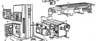
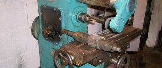
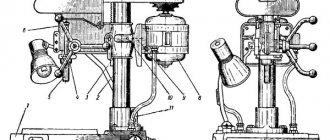
6R82G horizontal cantilever milling machine. Purpose and scope
6R82G milling machine has been produced since 1972 and replaced the outdated 6M82G model in production and was replaced by a more advanced model 6T82G.
The 6R83G model machines differ from the 6R82G by the increased size of the work table and a more powerful main movement motor.
The machine table model 6Р82Г (6Р83Г) is non-rotating.
6R82G horizontal cantilever milling machine is designed for milling all kinds of parts made of steel, cast iron and non-ferrous metals using cylindrical, disk, shaped, angular, face, end and other cutters in individual and mass production. The ability to configure the machine for various semi-automatic and automatic cycles allows you to successfully use the machines to perform operational work in production and automatic lines in large-scale production.
6R82G milling machine can process vertical and horizontal planes, grooves, corners, frames, gears, etc.
The technological capabilities of the machine can be expanded with the use of a dividing head, a rotary round table, an overhead universal head and other devices.
Main parameters of the horizontal cantilever milling machine 6R82G :
- Largest dimensions of the processed workpiece: 800 x 240 x 370 mm
- Electric motor power: 7.5 kW
- Machine weight: 2830 kg
The spindle 6r82g milling machine receives 19 stages of rotation from the gearbox, which provides free choice of cutting speeds in the range from 31.5 to 1600 rpm.
Spindle end - Morse taper KM50 (Ø128.570 mm) version 6 - according to GOST 24644 (Spindle ends and tool shanks for drilling, boring and milling machines). The tool or mandrel is inserted into the spindle and tightened with a cleaning rod. The protruding end of the cleaning rod is covered with a cap.
The feed box provides 18 stages of desktop feed in the longitudinal and transverse direction from 25 to 1250 mm/rev and in the vertical direction in the range of 8.3…416.6 mm/rev. The feed box of the 6r82g machine also provides rapid table movements at a speed of 3 m/min in the longitudinal and transverse directions and 1 m/min
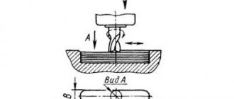
Using cams installed in the table grooves, you can configure the machine to operate in an automatic cycle, which can significantly increase the productivity of the machine in mass production.
In order to maintain the 6р82г in ideal working condition, it is necessary to regulate several components that require special attention:
- Gap in the earring bearing;
- Gap in the front spindle bearing;
- Speed dial clamp spring;
- Feed dial clamp spring;
- Feedbox safety clutch;
- High speed mechanism;
- Table wedges, slides, consoles;
- Gap in the longitudinal screw;
- Engagement spring for longitudinal code claw clutch.
Machine accuracy class N according to GOST 8-77.
The design features of the machine are:
- wide ranges of table feed values;
- quick-change tool mount;
- presence of a feed slowdown mechanism;
- slowing down the working feed in the automatic cycle;
- ability to work in automatic cycles, including frame processing;
- automatic lubrication of components;
- the use of non-contact high-speed electromagnetic clutches in the feed drive;
- increased accuracy of the machine due to the location of the cross-feed screw along the axis of the cutter;
- the ability to move the table simultaneously in two and three coordinates;
- the possibility of using a DC electric motor in the feed drive;
- possible further automation of machines through the use of digital display and operational control devices;
The machines are designed to perform various milling operations in both individual and large-scale production. In conditions of large-scale production, machines can also be successfully used to perform operational work.
The technical characteristics and high rigidity of the machines allow full use of the capabilities of both high-speed and carbide tools.
To reduce auxiliary time and ease of control, the machines provide:
- duplicated push-button-handle control (front and left side of the machine);
- starting and stopping the spindle and turning on the high speeds of the machine using buttons;
- control of table movements from handles, the direction of rotation of which coincides with the direction of movement of the table;
- changing speeds and feeds using single-handle selective mechanisms, allowing you to obtain any speed or feed by turning the dial without going through intermediate steps;
- DC braking.
The machines are automated and can be configured for various automatic cycles, which increases labor productivity, eliminates the need to maintain the machines by highly qualified workers and facilitates the possibility of organizing multi-machine maintenance.
History of production of machine tools by the Gorky plant, GZFS
In 1937
, the Gorky
Milling Machine Plant produced the first cantilever milling machines of the 6B series, models 6B12 and 6B82 , with a work table of 320 x 1250 mm (2nd standard size).
In 1951
6N of cantilever milling machines was launched into production 6N13PR machine received the “Grand Prix” at the world exhibition in Brussels in 1956.
In 1960
6M cantilever milling machines
was launched into production In 1972
6P of cantilever milling machines
was put into production In 1975
year, copying cantilever-milling machines were launched into production:
6Р13К .
In 1978
In 2009, copying cantilever-milling machines
6Р12К-1 , 6Р82К-1 .
In 1985
6T-1 of cantilever milling machines
was put into production In 1991
6T of cantilever milling machines was put into production
Are you here
The 6R82 and 6R82G cantilever milling machine is designed for processing parts made of various materials (steel, cast iron, non-ferrous materials) with disk, end, face and finger milling cutters in single-unit and large-scale production.
A milling machine can process parts of various configurations and complexity, vertical and horizontal planes, keyways, and gear teeth. It is also possible to mill various spirals by rotating the table around its axis by 45 degrees.
The technological capabilities of a milling machine can be expanded with the use of dividing heads, a rotary table or an overhead milling head.
The accuracy class of the machine is N - normal.
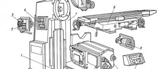
The device of the milling machine 6Р82
- Bed;
- Electrical equipment;
- Gearbox;
- Switch box;
- Table and slide;
- Console;
- Gearbox.
Controls of the milling machine 6Р82
- Handle for switching on transverse and vertical feed;
- Input switch;
- Coolant pump switch;
- Spindle speed switch;
- Flywheel for manual longitudinal movement of the spindle;
- Handle for switching spindle rotation speeds;
- Stop button;
- Spindle Start button;
- Arrow-indicator of spindle speeds;
- Spindle speed indicator;
- Button Quick table;
- Spindle pulse button;
- Light switch;
- Manual movement of the trunk;
- Earring clip;
- Automatic cycle mechanism sprocket;
- Handle for turning on longitudinal movements of the table;
- Table clamp;
- Switch for manual automatic control of longitudinal movements of the table;
- Flywheel for manual longitudinal movement of the machine table;
- Button Quick table;
- Spindle Start button;
- Button Table;
- Flywheel for manual movements of the machine table;
- Limb of the machine table movement mechanism;
- Vernier ring;
- Handle for manual vertical movements of the table;
- Swivel slide clamp;
- Handle for turning on vertical and transverse spindle feeds;
- Button for fixing the table feed switch fungus;
- Table feed switch fungus;
- Feed indicator;
- Table feed indicator arrow;
- Handle for clamping the slide on the console guides;
- Handle for turning on the longitudinal feed of the table;
- Switch for automatic or manual control of the round table;
- Console clamp handle on the machine bed;
- Trunk clamp on the machine bed.
Kinematic diagram of the 6Р82 cantilever milling machine
Gearbox of console milling machine 6Р82
The gearbox of the cantilever milling machine is mounted in a cast-iron frame body. The gearbox is connected to the shaft using an elastic coupling.
The gearbox spindle is a three-bearing shaft, the accuracy of which is determined by bearings 2 and 4. The third bearing is designed to support the spindle shank.
The axial clearance is adjusted by grinding rings 9 and 10. Increased play (clearance) in the front bearing is eliminated by grinding half rings 5 and tightening nut 1.
The gearbox is lubricated using a plunger pump with a capacity of 2 l/min. The remaining elements of the machine's gearbox are lubricated with spray oil coming from the holes in the tube located above the machine's gearbox.
Speed change box for milling machine 6Р82
The gearbox of the 6р82 milling machine allows you to select the required rotation speed without successive intermediate steps.
The rack moves using the handle 5, by means of sector 2 through the fork 10 it moves in the axial direction the roller 3 with the shift disk 9. The shift disk is rotated using the speed indicator 11 through the bevel gear 2 and 4. The disk has holes of a certain size located opposite the rack pins 5 and 7, meshing in pairs with gear 6.
Adjustment of spring 13 is carried out by plug 14, taking into account the fixation of the dial and the normal force when turning it.
Handle 5 is held in the on position by spring 4 and ball 3. Also, the handle tenon mates with the flange groove.
The gap to the bevel gear should not exceed 0.2 mm; due to this value, the disk can rotate up to 1 mm.
Milling machine feed box
The feed box provides working feeds (S) and accelerated movements of the table, console and slide.
As a result of the rotation of the blocks, the resulting speeds are transmitted to the shaft 12 through a ball safety clutch 4 and a bushing 3, connected by a key connection to the cam clutch 4 and the output shaft 12.
The friction clutch discs are connected through one to the clutch housing and the sleeve 15, which is connected by a key to the shaft 12.
When the cam clutch 4 is pressed on the end of the sleeve 5 and then on the nut 14, the disks 7 and 8 are compressed and transmit torque to the shaft 12 and gear 10.
Feed switch box for milling machine.
The feed switch box consists of the feed box assembly. The operating principle is similar to the operating principle of a gearbox.
To prevent axial displacement of disk 9 (Fig.), roller 1 is locked in the on position using two balls 6 and bushing 2. Getting into the annular groove of roller 3, the balls release roller 1 from fixation when button 4 is pressed.
The rotation of the switching disk 9 is fixed by a ball 8 through a locking sleeve 5 connected by a key to shaft 1.
6Р82Г Overall dimensions of the working space of a horizontal milling machine
Overall dimensions of the working space of the milling machine 6р82г
Landing and connecting bases for milling machine 6р82г
Placement of controls for the 6R82G cantilever milling machine
Location of controls for milling machine 6р82г
List of controls for the 6R82G milling machine
- Handle for turning on the transverse and vertical table feed (duplicate)
- On-off input switch
- Cooling pump on/off switch
- Spindle rotation direction switch “left-right”
- Handwheel for manual longitudinal movement of the table
- Spindle speed shift knob
- Stop button (duplicate)
- Spindle Start button (duplicate)
- Spindle speed indicator arrow
- Spindle speed indicator
- “Quick table” button (duplicate}
- Spindle pulse button
- Light switch
- Manual movement of the trunk
- Earring clips
- Automatic cycle sprocket
- Handle for turning on longitudinal table movements
- Table Clamps
- Switch for manual or automatic control of longitudinal table movement
- Handwheel for manual longitudinal movement of the table (duplicate)
- "Quick table" button
- Spindle start button
- Stop button
- Flywheel for manual lateral movements of the table
- Limb of the table transverse movement mechanism
- Vernier ring
- Handle for manual vertical movement of the table
- Clamping the rotary slide on the console guides
- Handle for turning on the transverse and vertical movements of the table
- Button for fixing the feed switch fungus
- Feed switch mushroom
- Table feed indicator
- Table feed indicator arrow
- Clamping handle for the rotary slide on the console guides
- Handle for turning on longitudinal movements of the table (duplicate)
- Switch for automatic or manual control and round table operation
- Console clamp handle on frame
- Trunk clamp on the frame
Specifications
The 6P82 machine processes parts weighing up to 250 kg. Main technical indicators of milling equipment:
- machine dimensions 2305×1950×1670 mm (length, width, height);
- net weight without tools and accessories 2900 kg;
- accuracy class N;
- 18 spindle speeds;
- table size 320×1250 mm;
- for fastening workpieces in the plane of the table 3 longitudinal T-shaped grooves;
- longitudinal movement of the table 800 mm;
- lateral movement 240 mm;
- vertical movement 370 mm.
The machine operates from a network with a voltage of 380 V. Power consumption at full load is 200 W.
Kinematic diagram of the 6R82G milling machine
Kinematic diagram of the milling machine 6р82г
Main drive
The main movement is driven by a flange electric motor through an elastic coupling.
The spindle speed is changed by moving three toothed blocks along spline shafts. The gearbox allows you to provide the spindle with 13 different speeds.
The feed drive is carried out from a flange electric motor mounted in the console. By means of two three-crown blocks and a movable gear wheel with a cam clutch, the feed box provides 18 different feeds, which are transmitted through a ball safety clutch to the console and then, when the corresponding cam clutch is turned on, to the screws of longitudinal, transverse and vertical movements.
Accelerated movements are obtained when the high-speed clutch is turned on, the rotation of which is carried out through intermediate gears directly from the feed electric motor.
The clutch is interlocked with the working feed clutch, which eliminates the possibility of their simultaneous activation.
A graph explaining the structure of the machine feed mechanism is shown in Fig. 5 (vertical feeds are three times less than longitudinal and transverse).
The frame is rigidly fixed to the base and secured with pins.
Kinematic diagram
The sequence of movements of all parts of the drive of the 6Р82Ш milling machine is determined by the interaction of its main components. The main working movements are the movement of the tool head with spindles and the table feed movement. The feedbox of a machine is characterized by a certain combination of rotation speed steps (18 in total). In this case, the lowest rotation speed is 0.52 s -1, and the highest is 26.6 s -1. In turn, the machine spindles are driven by their own electric motor using gears. The number of speeds is -12, with the lowest and highest speeds being 0.83 s -1 and 26.6 s -1 , respectively.
A separate branch of the kinematic diagram is the drive of the table movement mechanism in the transverse and longitudinal directions. The movement from a separate electric motor is transmitted through the clutch to gears. Due to the presence of different combinations of gear pairs, the range of possible horizontal feed speeds is from 25 to 2500 mm/min. Rapid feed is also possible - 3000 mm/min. In the vertical direction, the highest feed speed is 416 mm/min, and the lowest is 8.3 mm/min, with a feed speed in the installation (adjustment) mode of 1000 mm/min.
The kinematic diagram of the machine provides for electromechanical blocking from the simultaneous activation of several feeds of the work table.
Design of the main components of the horizontal milling machine 6R82G
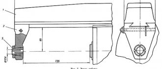
Trunk and earrings
The trunk and earrings can be moved and secured, the trunk in the frame guides, the earrings on the trunk guides.
The boring of the earring hole for the bearing is made individually for each machine, therefore, REPLACEMENT OF EARRINGS FROM ONE MACHINE TO ANOTHER IS NOT ALLOWED.
The clearance in the earring bearings is adjusted using nut 4 or screw 1 (Fig. 6) by heating. If the surface quality of the mandrel support sleeve is good (1.25; 0.63) and there is sufficient lubrication after running for one hour at maximum speed, the excess temperature of the inner surface of the tool cone should not exceed 55°C. Oil enters the bearing from the earring niche through the window in sleeve 3 and the wick. The oil supply is regulated by wire 2.
Gearbox
The gearbox is mounted directly in the frame body. The connection of the box to the electric motor shaft is carried out by an elastic coupling, which allows misalignment in the motor installation of up to 500-700 microns.
The gearbox can be inspected through the window on the right side.
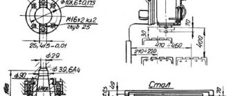
The machine spindle (Fig. 7) is a three-support shaft, the geometric accuracy of which is determined mainly by bearings 2 and 4. The bearing of the third support supports the spindle shank.
Axial play in the spindle is adjusted by grinding rings 9 and 10. Increased play in the front bearing is eliminated by grinding half rings 5 and tightening nut 1.
Regulation is carried out in the following order:
- with the trunk moved, remove cover 3 or the side cover on the right side of the machine and, unlocking it, loosen nut 1
- remove flange 6, spring ring 7, ring 8 and take out the half rings;
- By tightening nut 1, the backlash is selected. After checking the play in the bearing, the spindle is run in at maximum speed. When operating for an hour, the heating of the bearings should not exceed 60°C;
- measure the size of the gap between the bearing and the spindle shoulder, after which the rings are ground to the required amount. To eliminate radial play of 0.01 mm, the half rings must be ground by approximately 120 microns;
- the half rings are put in place. Check whether nut 1 is securely locked;
- parts 8, 7, 6 and 3 are installed in place.
Machine structure - main components and mechanisms
Kinematic diagram of the 6Р82 machine
List for the kinematic diagram of the 6Р82 machine
The passport and diagram of the 6P82 machine provides the following important structural parts, components and mechanisms:
bed
The bed refers to the foundation of the machine on which all its working parts, components and mechanisms are installed. The bed is mounted on the base plate of the milling machine. To give it rigidity, it is fixed with pins.
Trunk and earrings
These parts are placed on the bed. The trunk is secured and slides along the guides. The earrings are mounted on other guides, which are located on the trunk. Inside the trunk there is a gearbox, through which rotation is transmitted to the spindle.
Trunk with earrings machine 6Р82
The earrings are installed in holes specially provided for these purposes. The size of the holes is selected on an individual basis; the holes are different on each machine. Therefore, earrings cannot be interchangeable.
To adjust the gaps in the earring bearings, a special nut is provided. The adjustment is carried out with control based on the heating temperature of the earring. The heating temperature must be measured after the machine has been run in. The break-in time should be at least one hour, and the spindle speed should be set to the maximum. Before running in, make sure that the surface of the support bushing is in good condition and has a sufficient amount of lubricant. If the bearing temperature is between 50 and 60 °C, then adjustment can begin.
The oil that lubricates the bearings is located in special recesses (niches) located on the earring. Oil enters the bearing through the bushing window openings.
Gearbox
The 6P82 feed box is designed to ensure the movement of all moving parts and assemblies of the machine.
Feed box of the machine 6Р82
The main movement is provided by the drive, which includes a flanged electric motor and a coupling. The feed drive electric motor is installed inside the machine console. 6P82 cantilever milling machines, the passport of which provides for changing the speed of the spindle unit, can operate at 18 fixed speeds. Adjustment is carried out using toothed wheel blocks. The procedure for switching speeds is established by the operating instructions and the machine passport.
The feed box has a fast movement mode. This mode of movement is possible only after the overdrive clutch is activated. Friction transmission allows you to transmit torque from the main drive electric motor to the console, and only then to the movement screws.
Console
The description of the console is given by the passport. The console structure is made in the form of a metal box-shaped casting. It moves along vertical guides, which are connected to the frame.
The main feedbox mechanisms are located inside the console. These mechanisms are designed to transmit movement from the feed box to the screw shafts.
Gearbox
The gearbox on the 6P82 milling machine is located directly on the bed (in the trunk) and is designed to set the required speed mode for processing the part. The final assembly of the gearbox is its spindle, which is a shaft supported on three supports. The role of supports is performed by bearings.
Section along the spindle of a 6P82 machine
The spindle is designed to transmit torque from the power transmission to the tool mounted in it. The gearbox receives torque from the shaft of the machine's main drive electric motor, connected to each other by a coupling.
To transition from one optimal spindle rotation value to another, there is no need to sequentially move through high-speed intermediate steps. The main parts of the gearbox are: rack, shift handle, gears and gears.
To inspect the internal parts of the box, an inspection window is installed on it. Speed shifting is carried out by a handle. The required speed is selected using the spindle speed indicator. Using the gearbox, you can set 19 different spindle speeds.
Table and slide
These structural units are designed to move the table in longitudinal and transverse planes. The table is fixed on the guide rails and slides along them during the working cycle. Its platform is the basis for fastening parts to be processed, clamping devices and technological devices. To ensure that all this equipment is securely fastened and held on the table during operation, it is equipped with longitudinal grooves made in the form of a T-shaped profile. The table is driven by the lead screw, through a mechanism that transmits the rotational motion of the screw into the translational motion of the table.
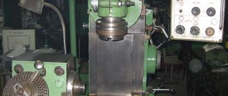
Appearance of the 6Р82 milling machine
The table and lead screw are connected at the ends of the table using brackets. The brackets are fixed with pins after installation. The mounting locations for the brackets are determined by the actual placement of the screw. To prevent longitudinal bending, the screw is placed on support bearings. The required tension of the lead screw is adjusted with a special nut.
The table rotation mechanism ensures that it is installed at an angle of 45° from its original position. The turning mechanism is located in the gap between the work table and the slide. To rotate the table to the optimal angle, you must do the following: move the slide to the most forward location; remove the tail cam that limits the transverse stroke, and only then unfold the table.
The slide acts as a buffer between the console and the table. They move along horizontal guides, which are located on the console.
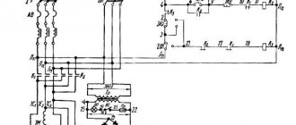
Electrical equipment of the 6R82G machine
Electrical diagram of milling machine 6R82G
Electrical diagram of a horizontal cantilever milling machine 6Р82г
Notes
- * - only for machines 6Р82Ш, 6Р83Ш
- ** - to the electrical diagram of the tool clamping mechanism
- *** - only for machines 6Р13Б
Supply network: Voltage 380 V, alternating current, frequency 50 Hz
Control circuits: Voltage 110 V, alternating current
Control circuits: Voltage 65 V, DC current
Local lighting: voltage 24 V.
Rated current (sum of rated currents of simultaneously operating electric motors) 20 A.
The rated current of the protective device (fuses, circuit breaker) at the power supply point is 63 A.
Electrical equipment is made according to the following documents: circuit diagram 6Р13.8.000Э3. connection diagram of the product R13.8.000E4.
Limits of machine use in terms of power and power loads
When operating at spindle speeds above 63 rpm, the limits of use of the main movement drive of machine tools are limited by the rated power of the installed electric motor.
The greatest cutting force allowed by the feed mechanism for longitudinal, transverse and vertical feeds, respectively, is: for machines 6Р82 and 6Р82Г - 1500, 1200, 500 kgf; for machines 6Р83 and 6Р83Г - 2000, 1200, 800 kgf.
The largest permissible diameter of cutters during roughing is: for 6R82G machines - 160 mm; for machines 6Р83Г - 200 mm.
If signs of vibration occur under certain cutting conditions, it is recommended to increase the feed per tooth or use cutters with an uneven pitch.
When working at low spindle speeds (n
| Parameter name | 6Р82 | 6R82G | 6Р83 | 6R83G |
| Cutter diameter, mm | 100 | 100 | 100 | 100 |
| Number of teeth | 8 | 8 | 8 | 8 |
| Milling width, mm | 100 | 100 | 150 | 150 |
| Milling depth, mm | 12 | 12 | 10 | 10 |
| Number of revolutions per minute, rpm | 50 | 50 | 50 | 50 |
| Longitudinal feed along the dial, mm/min | 125 | 125 | 125 | 125 |
In these modes, the clutch may periodically click.
The gap between the clutch discs is adjusted using nut 14, which is secured against spontaneous movement.
The feed switch mechanism is included in the feed box assembly. The principle of its operation is similar to the operation of a switch box
Schedule and composition of repair and maintenance work
When the machine operates under normal operating conditions and compliance with all operating and maintenance rules specified in this manual, the overhaul cycle (service life before major repairs during two-shift operation) is (mainly) at least 9 years when processing steel (mainly), and at least 8 years for cast iron years.
Maintenance and repair work is recommended to be carried out according to the repair work schedule (Fig. 39).
Machine inspection
- External inspection of the machine (without disassembling to identify defects) of the condition and operation of the machine as a whole and by components;
- Inspection and check of the condition of the main movement and feed drive mechanisms;
- Adjusting the table lead screw clearances;
- Spindle bearing adjustment;
- Checking the operation of speed and feed switching mechanisms;
- Regulation of the mechanisms for switching on cam clutches and feeds and the high-speed friction clutch;
- Adjustment of table wedges, slides, console and trunk;
- Inspection of guides, cleaning of nicks and burrs;
- Tightening loose fasteners;
- Checking the operation of the limiting cams;
- Checking the condition and minor repairs of cooling and lubrication systems;
- Checking the condition and repairing protective devices;
- Identification of parts that require replacement during the next repair (starting with the second minor repair);
Small machine repair
- Partial disassembly of components;
- Flushing all components;
- Adjustment or replacement of rolling bearings;
- Cleaning burrs and nicks on gear teeth, crackers and shift forks;
- Replacement and addition of friction discs of the high-speed clutch (starting from the second repair);
- Scraping and cleaning of wedges and strips;
- Cleaning the lead screws and replacing worn nuts;
- Cleaning nicks and burrs on the guides and working surface of the table;
- Replacing worn and broken fasteners
- Checking and adjusting the mechanisms for switching on speeds and feeds;
- Repair of lubrication and cooling systems;
- Testing the machine at idle speed, checking for noise, heating and accuracy of the workpiece.
Average machine repair
- Unit disassembly of the machine;
- Flushing all components;
- Inspection of parts of disassembled units;
- Drawing up a list of defects;
- Adjusting or replacing spindle bearings;
- Replacement or restoration of spline shafts;
- Replacement of worn bushings and bearings;
- Replacement of discs and fastener clutch parts;
- Replacement of worn gears;
- Restoring or replacing worn lead screws and nuts;
- Scraping or replacing adjusting wedges;
- Repair of pumps and fittings of lubrication and cooling systems;
- Correction by scraping or grinding the surfaces of the guides if their wear exceeds the permissible level;
- Painting the external surfaces of the machine;
- Running in the machine at idle (at all speeds and feeds) with checking for noise and heating;
- Checking the machine for accuracy and rigidity according to GOST 17734-72.
Overhaul of the machine
Major repairs are carried out with complete disassembly of all components of the machine, based on the results of which a defective estimate sheet must be drawn up. As a result of the repair, all worn components and parts of the machine must be restored or replaced, and its original accuracy, rigidity and power must be restored. The nature and scope of work for this type of repair are determined for specific operating conditions by a unified system of scheduled preventive maintenance.
Design and its specifics
The structural parts of the mechanism provide functionality and rigidity. Features of the connection of nodes determine the efficiency of work.
Trunk and earrings
It is possible to move the trunk in the guides of the frame. And the earrings can be moved in the trunk and also secured. Rearranging earrings from other equipment is not allowed, as they are mounted individually for each bearing. In case of breakdown, they are made independently.
The gap is adjusted using a screw and nut. The oil supply passes through a wire from the bearing. The temperature of the rotating part should not exceed 55 degrees during operation.
Gearbox
The gearbox is located in the frame housing and is visible through the window on the right. The spindle is a shaft with three supports, the third of which is connected to the tail. Adjustment occurs by removing the cover, loosening the nut and running in the spindle, reducing the gaps.
Lubrication occurs with a pump with a capacity of up to 2 liters per minute. It enters the nodes using tubes, and is sprayed onto the separated elements from the holes.
Gearbox
The operation of the switch box makes it possible to choose the optimal operating speed, but without going through all the intermediate steps. In a milling machine it is implemented using a device consisting of a rack, a handle, a fork, a shift disk, bevel gears, and a gear wheel.
Matching speeds is achieved by setting a certain ratio of gears. Lubrication occurs by supplying oil from the frame.
Gearbox
Necessary for moving the table, console and slide. Having received information from the control panel, the signal is sent to the output shaft and couplings. It is fed to the cam bushing, which compresses the springs that drive the gear. The supply to the nuts and discs changes depending on which couplings and the end of the bushing are used. In turn, this determines the movement of the wheel and the transmission of rotation.
Switching feeds is identical in principle of operation. Light clicking is acceptable in enhanced modes.
Technical characteristics of machine tools models 6Р82Г
| Parameter name | 6Р82 | 6R82G | 6Р83 | 6R83G |
| Accuracy class according to GOST 8-82 | N | N | N | N |
| Desktop | ||||
| Maximum load on the table (center), kg | 250 | 250 | 300 | 300 |
| Dimensions of the working surface of the table (length x width), mm | 1250 x 320 | 1250 x 320 | 1600 x 400 | 1600 x 400 |
| Number of T-slots Dimensions of T-slots | 3 | 3 | 3 | 3 |
| Maximum table movement longitudinal mechanical/manual, mm | 800/ 800 | 800/ 800 | 1000/ 1000 | 1000/ 1000 |
| Maximum table movement transverse mechanical/manual, mm | 240/ 250 | 240/ 250 | 300/ 320 | 300/ 320 |
| Maximum table movement vertical mechanical/manual, mm | 360/ 370 | 410/ 420 | 340/ 350 | 410/ 420 |
| The smallest and largest distance from the end of the spindle to the table during manual movement, mm * With manual movement and the lower limit cam removed | 30…400* | 30…450* | 30…380* | 30…450* |
| Distance from the spindle axis to the trunk, mm | 155 | 155 | 190 | 190 |
| Maximum table rotation angle, degrees | ±45 | No | ±45 | No |
| Price of one division of the table rotation scale, degrees | 1 | No | 1 | No |
| Movement of the table by one dial division (longitudinal, transverse, vertical), mm | 0,05 | 0,05 | 0,05 | 0,05 |
| Table movement per one revolution of the dial, longitudinal and transverse, mm | 6 | 6 | 6 | 6 |
| Movement of the table per one revolution of the dial, vertical, mm | 2 | 2 | 2 | 2 |
| Spindle | ||||
| Spindle speed, rpm | 31,5 — 1600 | 31,5 — 1600 | 31,5 — 1600 | 31,5 — 1600 |
| Number of spindle speeds | 18 | 18 | 18 | 18 |
| Maximum torque, kgf.m | 107 | 107 | 143 | 143 |
| Spindle end sketch | GOST 836-72 | GOST 836-72 | GOST 836-72 | GOST 836-72 |
| Spindle taper | 50 | 50 | 50 | 50 |
| Machine mechanics | ||||
| Fast table travel longitudinal and transverse, mm/min | 3/ 3/ 1 | 3/ 3/ 1 | 3/ 3/ 1 | 3/ 3/ 1 |
| Number of table feed stages | 18 | 18 | 18 | 18 |
| Working feed limits. Longitudinal and transverse, mm/min | 25…1250 | 25…1250 | 25…1250 | 25…1250 |
| Working feed limits. Vertical, mm/min | 8,3…416,6 | 8,3…416,6 | 8,3…416,6 | 8,3…416,6 |
| Feed stops (longitudinal, transverse, vertical) | There is | There is | There is | There is |
| Blocking manual and mechanical feed (longitudinal, transverse, vertical) | There is | There is | There is | There is |
| Blocking separate feed switching | There is | There is | There is | There is |
| Automatic intermittent feed Longitudinal | There is | There is | There is | There is |
| Automatic intermittent feed Cross and vertical | No | No | No | No |
| Spindle braking | There is | There is | There is | There is |
| Overload protection (clutch) | There is | There is | There is | There is |
| Drive unit | ||||
| Main drive motor Type | 4A132M4UZ | 4A132M4UZ | 4A132M4UZ | 4A132M4UZ |
| Electric motor of the main movement drive Number of revolutions per minute, rpm | 1460 | 1460 | 1460 | 1460 |
| Main motion drive electric motor Power, kW | 7,5 | 7,5 | 11 | 11 |
| Feed drive motor Type | 4А90L4УЗ | 4А90L4УЗ | 4А90L4УЗ | 4А90L4УЗ |
| Feed drive electric motor Number of revolutions per minute, rpm | 1430 | 1430 | 1430 | 1430 |
| Feed drive electric motor Power, kW | 2.2 | 2,2 | 3.0 | 3.0 |
| Electric coolant pump Type | PA-22U2 | PA-22U2 | PA-22U2 | PA-22U2 |
| Electric coolant pump Speed per minute, rpm | 2800 | 2800 | 2800 | 2800 |
| Electric coolant pump Power, kW | 0,12 | 0,12 | 0,12 | 0,12 |
| Coolant pump capacity, l/min | 22 | 22 | 22 | 22 |
| Dimensions and weight of the machine | ||||
| Machine dimensions (length x width x height), mm | 2305 x 1950 x 1670 | 2305 x 1950 x 1670 | 2560 x 2260 x 1770 | 2560 x 2260 x 1770 |
| Machine weight, kg | 2900 | 2830 | 3800 | 3700 |
Notes
- The full value of the moves indicated in the passport can be used only in the absence of parts and devices that limit the movement of the table, slide or console, for example:
- when using a rotary round table with a drive, as well as a dividing head with a guitar, the longitudinal stroke is reduced;
- when installing a mandrel with a cutter and an earring on the trunk in the spindle, the vertical stroke is reduced;
- when installing a workpiece or device hanging between the table and the frame mirror, the transverse travel of the slide is reduced;
- vertical movements in the rearmost position of the slide are limited by the spindle nuts if they are located vertically or when the spindle rotates. In this case, it is necessary to install limit stops taking into account the shutdown of the feed within the limits of the movement of the table, slide or console.
- In all cases of using full nameplate moves with mechanical feed, it is necessary to check the ability to operate at idle speed and carefully observe the operation of the machine during processing.
- Due to the presence of overtravels of the moving units due to inertia, the actual value of the mechanical strokes is reduced by 10-20 mm, according to which the limiting cams are screwed in.
- Table rotation up to 45° on the 6P83 machine is ensured when the slide is moved to the extreme forward position, and on the 6P82 machine it is also possible when the rear lateral travel limiting cam is removed.
- The given overall dimensions of the machines characterize the “packing” or their largest dimensions, provided that the moving units are installed in the middle position.
- If the frequency of the current in the power supply network of the machine tools is 60 Hz, then the number of revolutions of the electric motors is equal to: main movement - 1750 feed drive - 1730 cooling pump - 3360.
- Cantilever milling machines 6Р82, 6Р82Г, 6Р83, 6Р83Г. Manual,
- Cantilever milling machines 6Р82, 6Р83, 6Р82Г, 6Р83Г, 6Р82Ш, 6Р83Ш, 6Р12, 6Р13, 6Р12Б, 6Р13Б. Operating manual for electrical equipment 6Р82.ЭО.000 РЭ1,
- Avrutin S.V. Fundamentals of Milling, 1962
- Avrutin S.V. Milling, 1963
- Acherkan N.S. Metal-cutting machines, Volume 1, 1965
- Barbashov F.A. Milling 1973
- Barbashov F.A. Milling work (Vocational education), 1986
- Blumberg V.A. Milling machine handbook, 1984
- Grigoriev S.P. Practice of coordinate boring and milling work, 1980
- Kopylov Work on milling machines, 1971
- Kosovsky V.L. Handbook of a young milling operator, 1992
- Kuvshinsky V.V. Milling, 1977
- Nichkov A.G. Milling machines (Machinist's Library), 1977
- Pikus M.Yu. A mechanic's guide to repairing metal-cutting machines, 1987
- Plotitsyn V.G. Calculations of settings and adjustments of milling machines, 1969
- Plotitsyn V.G. Setting up milling machines, 1975
- Ryabov S.A. Modern milling machines and their equipment, 2006
- Skhirtladze A.G., Novikov V.Yu. Technological equipment for machine-building industries, 1980
- Tepinkichiev V.K. Metal cutting machines, 1973
- Chernov N.N. Metal cutting machines, 1988
- Frenkel S.Sh. Handbook of a young milling operator (3rd ed.) (Vocational education), 1978
Bibliography:
Related Links. Additional Information