Check 1. Straightness of the longitudinal movement of the caliper in the vertical plane
Test method
A. A level is installed on the support (closer to the tool holder) parallel to the direction of its movement.
The caliper moves longitudinally over the entire stroke length. Measurements are made no more than every 500 mm on machines with a slide stroke length of up to 6000 mm and no more than every 1000 mm on machines with a longer slide stroke length.
B. For machines with a slide stroke length of more than 6000 mm, testing can be done using communicating vessels, one of which is mounted on the slide, the other next to the machine.
Permissible deviations:
a) 0.02 mm per 1000 mm of caliper stroke length;
b) Over the entire length of the caliper stroke:
- 0.04 mm - for stroke lengths up to 2000 mm
- 0.06 mm - for stroke lengths up to 4000 mm
- 0.08 mm - for stroke lengths up to 8000 mm
- 0.10 mm - for stroke length up to 12000 mm
- 0.12 mm - for stroke lengths up to 16000 mm
- 0.16 mm - for stroke lengths up to 20,000 mm
Only convexity of the machine guides is allowed.
Installation of machines before accuracy testing
Before testing for accuracy, the machine is installed on a test bench or on a foundation on supports provided by the design of the machine. This must be done very carefully, since the geometric accuracy of the machine in some cases depends on the accuracy of its installation. There are the following types of installation of machines during testing:
1. Installing a machine on three support points is usually used for small-sized precision machines with a rigid frame that operates without additionally increasing its rigidity with a foundation.
Installation of the machine in a horizontal position is done by adjusting the supports. Alignment is carried out using levels installed in the longitudinal and transverse directions.
When installing the machine, all its moving parts (tables, carriages, supports, headstocks, etc.) must be in the middle positions.
The possibility of changing the position of the machine on supports during testing should be taken into account; To avoid errors, it is necessary to control the position of the bed with an additional level.
2. Installing the machine (during operation) on a number of supports of more than three is the most common method. In this case, the machine bed is rigidly connected to the foundation with bolts, which increases its rigidity.
When such a machine is installed for testing on a bench or foundation by alignment using wedges or shoes, the machine frame, which does not have sufficient rigidity, is deformed under the influence of its own weight and the weight of the units mounted on it.
Therefore, the installation of the machine on many supports is carried out by measuring the levels of deformation of the frame in its individual parts. By adjusting the supports, the bed is set to a position in which its deformations will be minimal. In the process of testing the machine for accuracy, additional adjustment of the supports may take place within the limits of permissible deformations of the frame, checking the relative position of the individual parts of the machine.
When testing machines whose frames have sufficient rigidity and operate without securing them with foundation bolts or on vibration-isolating supports, additional adjustment of the supports is not allowed during the accuracy test.
Before testing, the machine must be installed according to the installation drawing, but without tightening the foundation bolts.
The accuracy of machine installation before testing is specified in each section of the accuracy standards below.
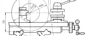
Check 2. Distortions of the caliper during its longitudinal movement
Test method
A level is placed on the support (closer to the tool holder) perpendicular to the direction of its movement.
The caliper moves longitudinally over the entire stroke length.
Measurements are made no more than every 500 mm on machines with a slide stroke length of up to 6000 mm and no more than every 1000 mm on machines with a longer slide stroke length.
When checking, the tool holder is shifted towards the center axis of the machine.
Permissible deviations:
a) For 1000 mm of caliper stroke length:
- 0.02/1000 for machines with the largest processing diameter up to 800 mm
- 0.03/1000 for machines with the largest processing diameter St. 800 mm
b) Over the entire length of the caliper stroke:
for machines with the largest processing diameter up to 800 mm
- 0.03/1000 - for stroke length up to 2,000 mm
- 0.04/1000 - for stroke length up to 4000 mm
- 0.06/1000 - for stroke length up to 8000 mm
- 0.08/1000 - for stroke length up to 12000 mm
- 0.10/1000 - for stroke length up to 20000 mm
for machines with the largest processing diameter up to 1600 mm:
- 0.04/1000 - for stroke length up to 2000 mm
- 0.05/1000 - for stroke length up to 4000 mm
- 0.08/1000 - for stroke length up to 8000 mm
- 0.10/1000 - for stroke length up to 20000 mm
for machines with the largest processing diameter over 1600 mm:
- 0.10/1000 - for stroke length up to 16000 mm
- 0.12/1000 - for stroke length up to 20000 mm
GOST 8-82
STATE STANDARD OF THE USSR UNION
METAL CUTTING MACHINES
GENERAL REQUIREMENTS FOR ACCURACY TESTS
GOST 8-82
USSR STATE COMMITTEE FOR PRODUCT QUALITY CONTROL AND STANDARDS
Moscow
STATE STANDARD OF THE USSR UNION
| METAL CUTTING MACHINES General requirements for accuracy tests Metal-cutting machine tools. General requirements to accuracy tests | GOST 8-82 |
Date
of introduction 07/01/83
Failure to comply with the standard is punishable by law
This standard applies to metal-cutting machines, including machines with numerical control, electrophysical and electrochemical, machine accessories, assembly units tested separately from the machines, manufactured for the needs of the national economy and export.
The standard establishes the basic concepts and principles for classifying machine tools by accuracy, general requirements for accuracy testing and general requirements for accuracy testing methods.
The requirements of this standard are mandatory, except for paragraphs. 1.9, 2.4, 2.14, 2.15, 3.4, 3.8, 3.9.
(Changed edition, Amendment No. 1,).
1. BASIC PROVISIONS
1.1. The accuracy of metal-cutting machines is determined by three groups of indicators:
indicators characterizing the accuracy of processing of product samples;
indicators characterizing the geometric accuracy of machine tools;
additional indicators.
1.2. Indicators characterizing the processing accuracy of product samples include:
accuracy of geometric shapes and location of processed surfaces of product samples;
constancy of batch sizes of product samples;
roughness of processed surfaces of product samples.
1.3. Indicators characterizing the geometric accuracy of the machine include:
accuracy of bases for installing workpieces and tools;
accuracy of movement trajectories of the working parts of the machine, carrying the workpiece and tool;
accuracy of the location of the axes of rotation and directions of linear movements of the working parts of the machine, carrying the workpiece and tool, relative to each other and relative to the bases;
accuracy of interconnected relative linear and angular movements of the working parts of the machine, carrying the workpiece and tool;
accuracy of dividing and installation movements of the working parts of the machine;
accuracy of coordinate movements (positioning) of the working parts of the machine, carrying the workpiece and tool;
the stability of some parameters with multiple repetitions of the test, for example, the accuracy of approach to a hard stop, the accuracy of small approach movements.
1.4. Additional indicators of machine accuracy include the ability to maintain the relative position of the working parts of the machine carrying the workpiece and tool, provided:
application of external load (stiffness indicators);
exposure to heat generated when the machine is idling;
machine vibrations that occur when the machine is idling.
(Changed edition, Amendment No. 2).
1.5. The scope of testing machines for accuracy should be minimal, but sufficient to obtain the necessary reliability of test results and assess the accuracy of the machine.
1.6. When choosing the accuracy parameters to be tested, preference should be given to the most significant of them, taking into account the degree of reproducibility of measurement results, stability and accuracy of measurement.
1.7. The list of machine tool accuracy indicators is determined by the standards for accuracy standards of machine tools of specific types and technical conditions.
1.8. The accuracy standards of a machine after medium and major repairs must comply with the requirements of the standards and technical conditions in force during the period of manufacture of the machine.
1.9. Classification of machines by accuracy
1.9.1. Five accuracy classes of machine tools are established according to the absolute classification system, designated in order of increasing accuracy level: N, P, B, A and C.
The division of machine tools into accuracy classes is carried out by type of machine, based on the requirements for processing accuracy.
The same accuracy class should include machines that provide the same processing accuracy of sample product surfaces corresponding in shape and size.
For certain types of machines intended only for grinding work, accuracy classes are not established.
(Changed edition, Amendment No. 1,).
1.9.2. The tolerance values of accuracy indicators when moving from one accuracy class to another are preferably taken according to a geometric series with a denominator j = 1.6. For specific indicators of geometric accuracy, it is allowed to take other values of j from 1.0 to 2.0.
(Changed edition, Amendment No. 3).
1.9.3. Accuracy classes for individual types of machine tools should be established in the standards for accuracy standards for these types of machine tools, and in the absence of standards, in the technical specifications for the machines.
1.9.4. Deleted
.
2. REQUIREMENTS FOR ACCURACY TESTS
2.1. Each machine manufactured at the manufacturing enterprise and each machine that has undergone medium and major repairs must be tested for accuracy.
If state standards for accuracy standards for machine tools of specific types contain instructions to test for rigidity, then it is carried out during acceptance and, if necessary, during periodic tests.
(Changed edition, Amendment No. 2,).
2.2. The accuracy test of the machine should be carried out when the machine is finally assembled.
2.3. Before testing for accuracy, installation of the machine, alignment of the machine and, if necessary, tightening of foundation bolts must be carried out in accordance with the instructions given in the operational documents for the machine, developed in accordance with GOST 2.601-68. In this case, the requirements for the foundation and installation of the machine on it must be observed.
Permissible deviations when aligning a machine by level are selected in accordance with standards for accuracy standards for specific types of machine tools, technical specifications or operational documents for the machine. If there are no such instructions, then the permissible deviations when aligning the machine to the level should not exceed 0.04 mm/m for machines of accuracy classes N and P and 0.02 mm/m for machines of a higher accuracy class.
In this case, the working parts of the machine, carrying the workpiece and the tool, must be in the middle working position. When aligning a machine with two or more working elements on one guide, the working elements should be positioned symmetrically in the middle of the guide, unless the standards for accuracy standards for specific types of machine tools and technical conditions contain special instructions.
The position of the levels when aligning specific machine models is established according to the operational documents for the machine.
(Changed edition, Amendment No. 1, 2).
2.4. Assembly units of machines are checked on stands.
2.5. Testing of the machine for accuracy by the manufacturer must be carried out after testing the machine at idle speed and in operation in accordance with GOST 7599-82 and after making the necessary adjustments in accordance with the regulatory and technical documentation for the machine.
When testing a machine for accuracy, only adjustments are allowed that are provided for by the standards for accuracy standards of machine tools of specific types, technical conditions and testing methods.
2.6. Inspections of individual assembly units and parts that cannot be carried out on finished machines without disassembling them must be carried out by the manufacturer during their manufacture and assembly, recording the results in the operational documents for the machine.
Machine tools should not be disassembled when testing for accuracy.
It is permissible to remove casings, shields, chucks, steady rests, mandrels, centers and other removable accessories to the machine, if this does not affect its accuracy.
2.7. Machine tools transported disassembled should be tested for accuracy at the consumer's site after their final assembly, alignment and adjustment.
2.8. In the process of testing machines for accuracy, the sequence of checks can be changed, but you should first check the surfaces and movements, which serve as the basis for subsequent checks.
2.9. When testing for accuracy, the moving components of the machine must be in the positions specified in the standards for accuracy standards for specific types of machine tools and technical conditions.
2.10. Testing of machines for accuracy in operation should be carried out by processing sample products. The dimensions, shapes and requirements for the base and machined surfaces of product samples must comply with GOST 25443-82 standards for accuracy standards for specific types of machine tools and technical conditions.
When testing automatic machines, a batch of sample products must be processed, the volume of which must meet the requirements of standards for accuracy standards for machine tools of specific types and technical conditions.
(Changed edition, Amendment No. 2,).
2.11. Fluctuations in the temperature of the working space during the period of testing machines for accuracy should not exceed the values specified in the standards for accuracy standards of machine tools of specific types, in technical specifications or in operational documents for machines.
If such instructions are absent, then for machines of accuracy classes B, A and C, fluctuations in the temperature of the working space should not exceed 2 °C. For machines of accuracy classes N and P, temperature fluctuations in the working space are not regulated.
When testing, machines must be protected from air flows, thermal radiation and other heat sources.
2.12. If the test result is significantly influenced by the heat generated during operation of the machine, then this test should be carried out after the machine is idling in accordance with the instructions of the standards for accuracy standards for specific types of machine tools, technical conditions, methods for checking accuracy parameters and operational documents for machines.
It is allowed to carry out these checks without preheating. In this case, the deviation from the initial position corresponding to the normal temperature of the machine should be normalized.
2.13. The required movements of the working bodies and other elements of the machine must be carried out manually or mechanically at speeds provided for in the technical specifications and other regulatory and technical documentation for the machine.
2.14. When testing for rigidity, a load that gradually increases to a given limit is applied to parts of the machine that carry the tool and the workpiece, and the relative movement of these parts is simultaneously measured.
2.15. The maximum permissible movements (lower limits of rigidity) of machine components carrying the tool and workpiece under certain loading forces are accepted as the rigidity indicators normalized in the standards.
2.16. All parts that need to be moved when testing for stiffness must be brought into the testing position by moving them in the direction opposite to the direction of the force component acting on them during testing.
2.17. Stiffness test conditions should approximate the loading conditions of a typical type of processing.
2.18. Standards that include testing of hardness must specify the testing conditions, including:
a) diagrams of the position of components and machine parts during the inspection process;
b) directions and magnitudes of loading forces and the point of their application;
c) directions and points at which movements should be measured;
d) methods for specifying loading forces and means of measuring them;
e) methods and means of measuring movements.
2.19. Special loading devices or machine mechanisms must be used as loading devices.
2.14 — 2.19. (Introduced additionally, Amendment No. 2).
3. REQUIREMENTS FOR TEST METHODS
3.1. Methods and measuring instruments must comply with GOST 22267-76, this standard, standards for accuracy standards for specific types of machine tools and technical specifications.
It is allowed to use testing methods and measuring instruments that differ from those specified in the standards for machine tool accuracy standards, provided that the required measurement accuracy is met and the reliability of the determination of the verified accuracy parameters is ensured.
Methods for checking the accuracy of machine tools, specified in the standards for specific types of machines and technical specifications as preferable, become mandatory in the event of disagreements between the manufacturer and the consumer.
(Changed edition, Amendment No. 2).
3.2. The measurement error should not exceed the values given in the standards for accuracy standards for specific types of machine tools. If such instructions are absent, then the measurement error, as a rule, should not exceed 30% before the start of the measured value.
(New edition, Amendment No. 3).
3.3. The error introduced when processing numerical measurement data is an integral part of the error according to clause 3.2 and should not exceed 0.1 of the measurement error.
3.4. When choosing verification methods, preference should be given to those whose results directly characterize the verified accuracy parameter without additional calculations.
3.5. Measuring instruments used to check the accuracy of machine tools must be certified. Measuring instruments must be standardized to the temperature of the working space. If necessary, the influence of temperature on the measurement results is corrected.
3.6. The location of the control parts of the mandrels must provide the ability to measure deviations at the lengths to which the tolerances are assigned. The dimensions of the control parts of the mandrels are indicated in Appendix 3.
The control mandrels must have a surface hardness of at least 53 HRCe and a roughness of the control parts of no more than Ra
0.32 microns according to GOST 2789-73.
3.7. When installing a control ruler over 500 mm long in a horizontal plane on two plane-parallel gauge blocks (tiles) of the same height, their distance from the ends of the ruler should be approximately 2/9 of the length of the ruler.
3.8. When determining the accuracy of the position or movement of the working body of the machine relative to a surface with insufficient shape accuracy, measurements are taken from a plane parallel to the adjacent one. It is allowed to use a surface plate or a ruler located on the surface.
3.9. In order to exclude from the measurement results deviations in the shape and location of the working surfaces of the measuring instruments (for example, deviations from the straightness and parallelism of the working surfaces of the straight edge or the generatrices of the control mandrel, deviations of the perpendicularity measuring instrument, etc.), it is allowed to carry out measurements in such a way that the specified deviations were compensated.
3.10. The tolerance value is equal to the largest permissible algebraic difference between the extreme readings of measuring instruments, with the exception of cases provided for in the standards for accuracy standards of machine tools of specific types and technical conditions.
If the same test gives different tolerances for an accuracy parameter for different measurement lengths, the tolerance assigned to the shorter length (smaller tolerance) applies to any portion of the measurement length.
(Changed edition, Amendment No. 3).
3.11. When carrying out measurements, the magnitudes and directions of permissible deviations established in the standards for accuracy standards of machine tools of specific types and technical conditions must be taken into account.
APPENDIX 1, 2.
Excluded.
APPENDIX 3
Recommended
Dimensions of control parts of mandrels, mm
| Length of the control part of the mandrel | Cantilever mandrel | Center mandrel | ||
| Outside diameter | Inner diameter | Outside diameter | Inner diameter | |
| 75 | 12 | — | — | — |
| 150 | 25 | — | 25; 40 | — |
| 200 | 32 | 23 | 32; 40 | — |
| 300 | 40 | 30* | 40 | — |
| 500 | 63 | 44* | 63 | 50 |
| 80 | 60* | — | — | |
| 1000 | — | — | 80 | 61 |
| 1600 | — | — | 125 | 105 |
* Average hole diameter.
APPENDIX 4.
Deleted.
INFORMATION DATA
1. DEVELOPED AND INTRODUCED by the Ministry of Machine Tool and Tool Industry
PERFORMERS
B.S. Vasiliev
, Doctor of Technical Sciences
sciences; A.N. Bankov,
Ph.D. tech. sciences;
S.S. Kedrov
, Ph.D.
tech. sciences; N.V.
Sokolova ;
N.V.
Shporin 2. APPROVED AND ENTERED INTO EFFECT by Resolution of the USSR State Committee on Standards dated September 23, 1982 No. 3728
3. The inspection period was 1992.
4. INSTEAD GOST 8-77
5. The standard fully complies with ST SEV 3111-81, ST SEV 3112-81, ST SEV 3115-81
The standard includes the requirements of the international standard ISO R 230
6. REFERENCE REGULATIVE AND TECHNICAL DOCUMENTS
| Designation of the referenced technical document | Item number, application |
| GOST 2.601-68 | 2.3 |
| GOST 2789-73 | 3.6 |
| GOST 7599-82 | 2.5 |
| GOST 22267-76 | 3.1 |
| GOST 25346-89 | 3.10, Appendix 4 |
| ST SEV 3111-81 | 1.9.1, appendices 1, 2 |
7. REISSUE (November 1989) with Amendments No. 1, 2, approved in February 1988, in October 1989 (IUS 5-88, 1-90)
CONTENT
| 1. Basic provisions. 1 2. Requirements for accuracy tests. 3 3. Requirements for verification methods. 5 |
Check 3. Straightness of the longitudinal movement of the caliper in the horizontal plane
Test method
A. For caliper stroke lengths up to 3000 mm, the check is carried out using a cylindrical mandrel fixed between the centers of the headstock and tailstock, and an indicator.
An indicator is installed on the support so that its measuring rod touches the side generatrix of the mandrel. The indicator readings at the ends of the mandrel should be the same (this is achieved by appropriately installing the tailstock).
B. When the caliper stroke length is over 3000 mm, the check is carried out using a microscope mounted on the caliper and a string stretched along the frame guides.
The axis of the microscope lens is located vertically. The intersection of the threads of the ocular plate is combined with the side generatrix of the string at the beginning and end of the caliper stroke.
After achieving the specified conditions, the caliper moves in the longitudinal direction over the entire stroke length.
When checking, the tool holder is shifted towards the center axis of the machine.
The error is determined by the ordinate of the deviation of the trajectory from the original straight line.
Permissible deviations:
a) 0.02 mm per 1000 mm of caliper stroke length;
b) over the entire length of the caliper stroke:
- 0.03 mm - for stroke length up to 2000 mm
- 0.04 mm - for stroke lengths up to 4000 mm
- 0.05 mm - for stroke lengths up to 8000 mm
- 0.06 mm - for stroke length up to 12000 mm
- 0.08 mm - for stroke lengths up to 16000 mm
- 0.10 mm - for stroke lengths up to 20,000 mm
When moving, the support can only have a deviation towards the axis of the machine centers
Checking lathes for geometric and technological accuracy
Speaking about the accuracy of a lathe, we mean compliance of the equipment passport data with the following parameters:
- movement of those elements on which the workpiece is located;
- the location of those surfaces with which the tool or workpiece is based;
- shape of base surfaces.
After final assembly and testing at the factory, as well as after repairs, the machines receive an acceptance certificate, and only after that they are put into operation.
Accuracy requirements are indicated in the machine passport.
Measurements to identify errors should be carried out regularly in accordance with GOST standards.
Download GOST 8-82 “Metal-cutting machines. General requirements for accuracy tests"
Download GOST 18097-93 “Screw-cutting and turning machines. Basic dimensions. Accuracy standards."
In the process of using turning equipment, wear occurs on its parts, because When processing products, forces appear that produce various deformations. During operation, the machine heats up and thermal deformations are formed under the influence of temperature. All these defects have a negative impact on the quality of processed parts. And in order to restore the machine’s passport performance, worn parts should be periodically repaired.
High-quality testing of lathes in accordance with the state standard largely depends on how correctly it is installed on the test bench. Installation on the stand must be carried out strictly, observing the installation drawing. The most common method is to install more than 3 supports. Note that all moving parts of the machine being tested must be in the middle positions.
The geometric accuracy of a lathe characterizes the quality of manufacturing parts, so the workpiece must be installed on a geometrically correct surface.
To determine the degree of wear, you need to install a ruler on each of the bed guides in turn. After this, the distance between the guides and the control ruler is determined with a feeler gauge. The permissible value of such wear according to the state standard should not exceed 0.02 mm.
An equally important factor is the alignment of the horizontal guides of the frame. It can be determined by moving a special level along the surface of the guides, which will show the value of the existing deviation. The maximum permissible deviation according to GOST cannot exceed 0.05 mm. And the parallelism between the bed guides for the thrust (tailstock) and the carriage can be checked using a special measuring indicator. It must be mounted on a carriage with a support and, by moving the carriage, determine the amount of deviation.
Checking the parallelism of the guides
Checking the horizontal position of the bed guides
Also, the accuracy of the lathe will help determine the runout of the rotating spindle into which the workpiece is attached. Be sure to maintain parallelism between the spindle axis and the bed guides. During the test, a special control mandrel is installed in the shaft hole and checked for runout along its entire length.
Checking that the spindle axis is parallel to the frame guides: a - the indicator is fixed in a vertical plane; b — the indicator is fixed in the horizontal plane
When carrying out a technological check for accuracy, it is also worth paying attention to the rotation of the journals of the rotating shaft. Beating when they rotate is not acceptable. It is necessary to fix the indicator in the cutting head, then rest its pin in the spindle neck and take measurements. According to GOST, the value should not exceed 0.01 mm. It is not permissible for the spindle to deviate from the axis when rotating.
Checking the spindle runout: a - checking the spindle neck runout; b - checking the axial movement of the spindle; c — checking the front center runout
Also, one of the important measurements when checking a lathe for accuracy is determining the pitch accuracy of the lead screw. The magnitude of the deviation in accordance with GOST is determined using the following methodology:
- a threaded mandrel is installed in the centers of the headstock and tailstock;
- a nut in the shape of a cylinder and having a groove is screwed onto this mandrel;
- a holder ball is installed in the groove of this cylindrical nut;
- the indicator fixed in the holder rests against the end part of the cylindrical nut;
- the lathe is adjusted to the thread pitch;
- the indicator detects deviations.
Checking the pitch accuracy of the lead screw
Main errors in the shape of processed workpieces:
- non-linearity;
- conicality;
- lack of parallelism;
- non-roundness;
- non-concentricity.
Tools used during testing:
- control line;
- level;
- dipstick;
- square;
- measuring indicator;
- threaded mandrel;
- control mandrel;
- cylindrical nut;
- holder.
When performing measurements, you should use only those instruments that have passed metrological verification with the error taken into account.
Check 4. Parallelism of the tailstock guides to the direction of longitudinal movement of the caliper
Test method
An indicator is installed on the caliper so that its measuring rod touches the tailstock guide.
The check is carried out one by one for each tailstock guide - when using one indicator, or for all guides simultaneously - when using a set of indicators.
Measurements are taken in planes perpendicular to the corresponding tailstock guides.
The caliper moves longitudinally along the entire length of the tailstock guides.
Permissible deviations:
1. For vertical guides:
a) 0.03 mm per 1000 mm of caliper stroke length;
b) over the entire length of the caliper stroke.
- 0.04 mm - for stroke lengths up to 2000 mm
- 0.05 mm - for stroke lengths up to 4000 mm
- 0.06 mm - for stroke lengths up to 8000 mm
- 0.07 mm - for stroke length up to 12000 mm
- 0.08 mm - for stroke lengths up to 16000 mm
- 0.10 mm - for stroke lengths up to 20,000 mm
2. For horizontal and inclined guides:
a) 0.02 mm per 1000 mm of caliper stroke length;
b) over the entire length of the caliper stroke:
- 0.025 mm - for stroke lengths up to 2000 mm
- 0.03 mm - for stroke length up to 4000 mm
- 0.04 mm - for stroke lengths up to 8000 mm
- 0.05 mm - for stroke length up to 12000 mm
- 0.06 mm - for stroke length up to 16000 mm
- 0.07 mm - for stroke lengths up to 20,000 mm
Check 5. Radial runout of the centering journal of the headstock spindle
Test method
An indicator is installed on the machine so that its measuring rod touches the centering journal of the spindle and is perpendicular to the generatrix.
The spindle is rotated.
Permissible deviations:
- 0.010 mm - for machines with the largest processing diameter up to 400 mm
- 0.015 mm - for machines with the largest processing diameter up to 800 mm
- 0.020 mm - for machines with the largest processing diameter up to 1600 mm
- 0.030 mm - for machines with the largest processing diameter up to 3200 mm
- 0.040 mm - for machines with the largest processing diameter up to 6300 mm
Note This check does not apply to lathes with fixed faceplates.
The general formulation of the problem of accuracy is outlined. The influence of accuracy on the operation of machine and machine parts is shown. The main methods for calculating the accuracy of machine tools and individual components, specific recommendations for increasing the accuracy of machine tools are presented, and the development and experience of ENIMS are reflected. For engineering and technical workers of machine-building enterprises; The book may be useful to scientists.
Size: 9.26 MB Format: djvu Link not working? Write about it in the comments.
Table of contents:
Chapter 1. The problem of accuracy in mechanical engineering and machine tools 1.1. General provisions 1.2. The influence of manufacturing accuracy on the operation of machine parts and machine tools
Chapter 2. General information about the accuracy of machine tools 2.1. Requirements for the accuracy of machines 2.2. Testing machines for accuracy 2.3. Experimental balances of processing accuracy
Chapter 3. Basics of the variational method for calculating the accuracy of machine tools 3.1. Mathematical model of the form-generating system of the machine 3.2. Analysis of processed surfaces 3.3. Schematic diagram for calculating machine characteristics using the shaping function
Chapter 4. Calculation of the position accuracy of an individual link of the forming system 4.1. Mathematical description of small displacements of a rigid body 4.2. Calculation of geometric errors in the position of machine components 4.3. Calculation of the error in the position of the node due to elastic deformations of the supports 4.4. Accounting for deformations of machine components and other elements of the AIDS system
Chapter 5. Calculations of output accuracy of machine tools 5.1. General information 5.2. System for assessing the accuracy of machined surfaces 5.3. Errors in shaping schemes 5.4. Software and mathematical support for calculating the accuracy of machine tools 5.5. Balance of accuracy of lathe 5.6. Evaluation of the output accuracy of the spindle assembly 5.7. Analysis of the accuracy of gear grinding machines operating with a flat wheel 5.8. Study on the accuracy of CNC contour grinding machine
Chapter 6. Calculation and reference data on the criteria determining the accuracy of machine tools 6.1. Hardness 6.2. Temperature fields and deformations 6.3. Wear resistance
Chapter 7. Fragments of calculations of the accuracy of machine components 7.1. Setting questions 7.2. Spindle units 7.3. Carrying and guiding systems Chapter 8. Recommendations for increasing accuracy 8.1. General activities 8.2. Increasing the accuracy of machine tools according to individual performance criteria 8.3. Improving the designs of components to increase the accuracy of machine tools 8.4. Increasing the accuracy of machine tools of individual groups 8.5. Increasing the accuracy of automated production machines 8.6. Intersectoral and organizational issues of increasing accuracy
Bibliography
Application
Similar books:
- Machine drives: Directory/V. V. Dlougy, T. I. Mukha, A. P. Tsupikov, B. V. Yanush; Under general ed. V. V. Dlougogo. — 2nd ed., revised. and additional - L.: Mechanical Engineering, Leningrad. department, 1982. - 383 p., ill.
Tags: Deformation of machine components, Machine rigidity, Machine wear resistance, Machine testing, Improving machine accuracy, Calculation of machine error, Accuracy of gear grinding machines, Machine accuracy, Spindle unit
Check 6. Radial runout of the headstock spindle hole axis
Test method
A cylindrical mandrel is tightly inserted into the hole in the headstock spindle.
An indicator is installed on the machine so that its measuring rod touches the surface of the mandrel.
The spindle is rotated.
Measurements are taken at the end of the spindle and at a distance of l=300 mm from it.
Permissible deviations:
a) When measuring at the end of the spindle:
- 0.010 mm - for machines with the largest processing diameter up to 400 mm
- 0.015 mm - for machines with the largest processing diameter up to 800 mm
- 0.020 mm - for machines with the largest processing diameter up to 1600 mm
- 0.030 mm - for machines with the largest processing diameter up to 3200 mm
- 0.040 mm - for machines with the largest processing diameter up to 6300 mm
b) When measuring at a distance l=300 mm from the end of the spindle:
- 0.020 mm - for machines with the largest processing diameter up to 400 mm
- 0.025 mm - for machines with the largest processing diameter up to 800 mm
- 0.030 mm - for machines with the largest processing diameter up to 1600 mm
- 0.050 mm - for machines with the largest processing diameter up to 3200 mm
- 0.060 mm - for machines with the largest processing diameter up to 6300 mm
Classification of metal-cutting machines by accuracy
According to the classification of machine tools developed in the USSR, they are divided into five classes according to accuracy, shown in Table. 171.
Table 171
| Machine accuracy class | Accuracy class designation | The relationship between the basic tolerances of machine tool accuracy |
| Normal precision machine tools | N | 1 |
| High precision machines | P | 0,6 |
| High precision machines | IN | 0,4 |
| Particularly high precision machines | A | 0,25 |
| Ultra-precision machines | WITH | 0,15 |
As can be seen from table. 171 the ratio between tolerance values when moving from class to class for most accuracy indicators is assumed to be φ = 1.6.
This ratio makes it possible to harmonize the requirements for the accuracy of the machine with the requirements for the accuracy of the products processed on it, since the coefficient of 1.6 is taken into account in the tolerance systems of parameters that characterize the accuracy of the surfaces of widely used products. High-precision machines, as a rule, are manufactured on the basis of normal-precision machines, differing from them mainly in more precise manufacturing and selection of individual parts and improved installation quality.
High and especially high precision machines differ from previous ones in the special design features of individual elements, the high precision of their manufacture and special operating conditions.
Ultra-precision machines are designed for processing parts of the highest precision - indexing gears and disks, standard gears, measuring screws, etc.
When accepting machines of a higher accuracy class than those regulated by the standards given below, you can use the accepted ratio of the main accuracy indicators when moving from a lower to a higher class by multiplying the permissible deviations by 0.6.
Check 7. Axial runout of the headstock spindle
Test method
A short mandrel is inserted into the hole in the headstock spindle, the end surface of which is perpendicular to its axis.
The indicator is installed on the machine so that its measuring rod touches the end of the mandrel at its center or the surface of the ball inserted into the center hole of the mandrel (in this case, the measuring rod of the indicator is flat).
The spindle is rotated.
The check is carried out with the thrust bearings tightened.
Permissible deviations:
Permissible deviations:
- 0.010 mm - for machines with the largest processing diameter up to 400 mm
- 0.015 mm - for machines with the largest processing diameter up to 800 mm
- 0.020 mm - for machines with the largest processing diameter up to 1600 mm
- 0.030 mm - for machines with the largest processing diameter up to 3200 mm
- 0.040 mm - for machines with the largest processing diameter up to 6300 mm
Control regulations
Planned control of the technological accuracy of metalworking equipment is carried out according to a schedule, which is drawn up in accordance with a special document - a list of machine equipment. It contains information about the frequency of technological operations that affect the accuracy of product manufacturing. This document also contains information about the operating modes of the machines.
The check can be not only scheduled, but also performed in case of emergency equipment failures. In this case, control measures are carried out in accordance with regulations developed to eliminate force majeure circumstances.
Any inspections - both scheduled and emergency - are carried out subject to the temporary removal of machines from operation. For this reason, developing a schedule of control activities is very important for planning both production activities and equipment modernization. It remains to add that, as a rule, the chief technologist of the plant is responsible for this area of the enterprise’s work.
Check 8. Axial runout of the headstock spindle support collar
Test method
An indicator is installed on the machine so that its measuring rod touches the end surface of the headstock spindle collar at the greatest possible distance from the center.
The spindle is rotated.
Measurements are made at at least two diametrically opposite points of the same diameter (the indicator is rearranged).
The error is defined as the largest value of the indicator readings.
The check is carried out with the thrust bearings tightened.
Permissible deviations:
Permissible deviations:
- 0.020 mm - for machines with the largest processing diameter up to 400 mm
- 0.025 mm - for machines with the largest processing diameter up to 800 mm
- 0.030 mm - for machines with the largest processing diameter up to 1600 mm
- 0.040 mm - for machines with the largest processing diameter up to 3200 mm
- 0.050 mm - for machines with the largest processing diameter up to 6300 mm
Note. The check does not apply to lathes with fixed faceplates.
FAQ: GOST standards for accuracy and measurement
GOST 8-82 Metal-cutting machines. General requirements for accuracy tests
GOST R ISO 230-1-2010 Testing of machine tools. Part 1. Methods for measuring geometric parameters
GOST 22267-76 Metal-cutting machines. Schemes and methods for measuring geometric parameters
GOST 7599-82 Metalworking machines. General technical conditions
GOST 27843-2006 Testing of machine tools. Determination of the accuracy and repeatability of positioning of axes with numerical control (GOST 27843-88)
GOST 30544-97 Metal-cutting machines. Methods for checking the accuracy and consistency of working out a circular trajectory
Product samples
GOST 25889.1-83 Metal-cutting machines. Methods for checking the roundness of a sample product
GOST 25889.2-83 Metal-cutting machines. Methods for checking the parallelism of two flat surfaces of a sample product
GOST 25889.3-83 Metal-cutting machines. Methods for checking the perpendicularity of two flat surfaces of a sample product
GOST 25889.4-86 Metal-cutting machines. Method for checking the constancy of the diameters of a sample product
GOST 26189-84 Metal-cutting machines. Method for comprehensive verification of parallelism and straightness of two flat surfaces of a sample product
GOST 26190-84 Metal-cutting machines. Methods for checking the size constancy of cylindrical product samples within one batch
GOST 26542-85 Metal-cutting machines. Methods for checking the end runout of the surfaces of a sample product
GOST 25443-82 Metal-cutting machines. Sample products to check processing accuracy. General technical requirements
GOST 30527-97 Metal-cutting machines. Methods for checking the processing accuracy of a sample product
Lathes
GOST 18097-93 Screw-cutting and turning machines. Basic dimensions. Accuracy standards
GOST 3179-72 Turret lathes. Main Dimensions
GOST 17-70 Turret lathes. Accuracy standards
GOST 44-93 Vertical turning machines. Basic parameters and dimensions. Accuracy and rigidity standards
GOST 8427-75 Longitudinal turning machines. Automatic machines. Main Dimensions
GOST 8831-79 Longitudinal turning machines. Automatic machines. Accuracy standards
GOST 21608-76 Lathes with numerical control. Main parameters and dimensions
GOST 6820-75 Multi-spindle vertical cartridge lathes, semi-automatic. Accuracy and rigidity standards
GOST 19660-74 Backing lathes. Main Dimensions
GOST 9886-73 Horizontal double-sided semi-automatic machines for end processing and centering. Main Dimensions
Drilling machines
GOST 1222-80 Radial drilling machines. Main Dimensions
GOST 98-83 Radial drilling machines. Accuracy and rigidity standards
GOST 21611-82 Vertical drilling machines with numerical control. Main parameters and connecting dimensions
GOST 370-93 Vertical drilling machines. Basic dimensions. Accuracy and rigidity standards
Boring machines
GOST 7058-84 Horizontal boring machines. Main Dimensions
GOST 2110-93 Horizontal boring machines with a cross table. Accuracy standards
GOST 18098-94 Jig boring and jig grinding machines. Accuracy standards
GOST 30175-94 Jig boring and jig grinding machines. Main Dimensions
GOST 21613-82 Vertical coordinate boring machines with numerical program control. Main parameters and connecting dimensions
GOST 9520-73 Vertical finishing and boring machines. Main Dimensions
GOST 594-82 Vertical finishing and boring machines. Accuracy standards
GOST 9547-80 Horizontal finishing and boring machines with a movable table. Main Dimensions
GOST 11576-83 Horizontal finishing and boring machines with a movable table. Accuracy standards
Surface grinding machines
GOST 13135-90 Surface grinding machines with a rectangular table. Basic dimensions. Accuracy standards
GOST 14-88 Surface grinding machines with a round table and a horizontal spindle. Basic dimensions. Accuracy standards
GOST 27-88 Surface grinding machines with a round extendable table and a vertical spindle. Basic dimensions. Accuracy and rigidity standards
GOST 273-90 Surface grinding machines with a cross table and a horizontal spindle. Basic dimensions. Accuracy and rigidity standards
Cylindrical grinding machines
GOST 11654-90 Cylindrical grinding machines. Basic parameters and dimensions. Accuracy standards
GOST 13510-93 Centerless cylindrical grinding machines. Basic parameters and dimensions. Accuracy and rigidity standards
GOST 30677-2000 Cylindrical grinding machines. Covers. Types and main sizes
GOST 30676-2000 Cylindrical grinding machines. Flanges for mounting grinding wheels. Design and dimensions
Various grinding
GOST 25-90 Internal grinding machines. Basic parameters and dimensions. Accuracy standards
GOST 9735-87 Profile grinding machines. Accuracy standards
GOST 30512-97 Roll grinding machines. Accuracy standards
Sharpening machines
GOST 599-93 Grinding machines for twist drills. Basic dimensions. Accuracy standards
GOST 8308-72 Universal grinding machines. Main Dimensions
GOST 1584-87 Universal grinding machines. Accuracy standards
GOST 16929-90 Machines for sharpening flat knives with a straight cutting edge. Accuracy standards
GOST 28651-90 Machines for sharpening band saws. Main parameters. Accuracy standards
GOST 20404-88 Machines for sharpening circular saws. Accuracy and rigidity standards
GOST R 50340-92 Machines for sharpening wood-cutting tools. Severity standards
GOST 627-93 Grinding machines for cutters. Basic dimensions. Accuracy standards
GOST 28650-90 Machines for sharpening frame saws. Main parameters. Accuracy standards
GOST 9990-71 Machines for sharpening flat knives with a straight cutting edge. Main settings
Milling machines
GOST 6955-79 Longitudinal milling machines. Main Dimensions
GOST 18101-85 Longitudinal milling machines. Accuracy and rigidity standards
GOST 17734-88 Console milling machines. Accuracy and rigidity standards
GOST 26016-83 Wide-universal tool milling machines. Accuracy standards
GOST 9726-89 Vertical milling machines with a cross table. Terminology. Basic dimensions. Accuracy and rigidity standards
GOST 10460-72 Horizontal copying and milling machines. Main Dimensions
Slotting machines
GOST 1141-74 Slotting machines. Main Dimensions
GOST 26-75 Slotting machines. Accuracy and rigidity standards
Planing machines
GOST 439-73 Longitudinal planing machines. Main Dimensions
GOST 35-85 Longitudinal planing machines. Accuracy and rigidity standards
GOST 1105-74 Cross-planing machines. Main Dimensions
Electroerosive machines
GOST 20551-93 Electroerosive cutting machines. Basic dimensions. Accuracy standards
GOST 24772-81 Electrochemical copying and piercing machines. Main parameters and dimensions
GOST 30098-93 Electroerosive copying and piercing machines. Basic dimensions. Accuracy standards
Aggregate machines
GOST 24380-91 Beds of aggregate machines. Basic dimensions. Accuracy standards
GOST 19468-81 Modular machines. Main Dimensions
Gear, spline, and thread processing machines
Measuring tool
GOST 10905-86 Testing and marking plates. Specifications
GOST 8026-92 Calibration rulers. Specifications
GOST 3749-77 Test squares 90 degrees. Specifications
GOST 9392-89 Frame and block levels. Specifications
GOST 15982-70 Levels with micrometric ampoule supply. Methods and means of verification
GOST 11196-74 Levels with micrometric ampoule supply. Specifications
GOST 2386-73 Level ampoules.
Specifications https://vsegost.com/C…/17/17360.shtml Modified on January 11, 2015 by tmpr
Check 9. Parallelism of the headstock spindle axis to the direction of longitudinal movement of the caliper
Test method
A cylindrical mandrel is tightly inserted into the hole in the headstock spindle.
An indicator is installed on the support so that its measuring rod touches the surface of the mandrel:
a) along its upper generatrix;
b) along its lateral generatrix. The support moves along the bed.
In each section of the test, measurements are taken along two diametrically opposite generatrices (when the spindle is rotated 180°).
The error is determined by the arithmetic mean of the results of both measurements in a given plane.
Permissible deviations:
a) When measured in a vertical plane:
- 0.030 mm over a length of 300 mm - for machines with the largest processing diameter up to 800 mm
- 0.050 mm over a length of 300 mm - for machines with the largest processing diameter up to 1600 mm
- 0.060 mm over a length of 300 mm - for machines with the largest processing diameter up to 3200 mm
- 0.080 mm over a length of 300 mm - for machines with the largest processing diameter up to 6300 mm
b) When measuring in the horizontal plane:
- 0.012 mm over a length of 300 mm - for machines with the largest processing diameter up to 400 mm
- 0.015 mm over a length of 300 mm - for machines with the largest processing diameter up to 800 mm
- 0.020 mm over a length of 300 mm - for machines with the largest processing diameter up to 1600 mm
- 0.025 mm over a length of 300 mm - for machines with the largest processing diameter up to 3200 mm
- 0.060 mm over a length of 300 mm - for machines with the largest processing diameter up to 6300 mm
The free end of the mandrel can only deviate upward and towards the front caliper cutter.
Tool Measuring and Control System (Tool Setter)
Before moving on to the description of measuring systems, you should answer the question that often arises when purchasing your first CNC machine: “Is it possible to do without this system?” An important step in assessing the capabilities and needs of this equipment is to understand the principles of indication and recalculation of coordinates on a CNC machine.
How to bind an instrument
So, for any CNC machine there is the concept of a machine zero, or more precisely, a zero position for each node that can move and/or rotate with coordinates indicated. Accordingly, at this zero position, the translation/rotation coordinate is zero. The machine zero and the direction of movement/rotation, which is determined by the sign, constitute the concept of the machine coordinate system or machine coordinates. These coordinates are unchanged, measured from machine zero, and can always be displayed on the operator panel. However, it is difficult to use them for programming the processing of a product, since the coordinates are counted from a point located outside the part. To compile a control program, the coordinate system of the part is used. That is, they add a new coordinate reference and assign it in the CNC system ( Fig. 2 ). For this purpose, it has a Work Offsets section - offset of the working coordinate system. There can be several coordinate systems for a part; they are assigned numbers. For each system, the Work Offsets section specifies the machine coordinates of the origin. When the selected workpiece coordinate system is activated in the specified machine coordinates, the position of the axes is reset to zero.
Rice. 2. Machine coordinate system
Rice. 3. Tool coordinate system
Thanks to the automatic tool change system, all the tools that are planned to be used to execute the program are loaded into the machine. Each is assigned a number according to the tool cell. However, each tool will have its own design point (programmed point) and projection from the chuck (or turret) ( Fig. 3 ). Thus, the third coordinate system is individual for each tool. There are several sections in the Tools Offset section of the CNC system. The first concerns the tool overhang - length corrector. It indicates the machine coordinate that defines the tip of the tool. For turning cutters there are two such coordinates - ZX, for milling cutters one - Z. On the machine, these coordinates are determined by approaching the tool to the surface, the position of which relative to the reference system of the part is known. The tool is brought to contact. During touching, machine coordinates are recorded, then the distance from the touching surface to the zero of the part is added to them and this value is recorded in the length corrector table. The next section includes information about the diameter of the tool. There is also a section on tool wear. The CNC system will use the values entered there to shift the original processing path obtained from the control program. Naturally, such input of tool data into the coordinate system takes time and does not exclude errors.
How the automated tool binding system works
The main task of the system for dimensional adjustment of tools is to eliminate errors that arise when manually carrying out the above-described process and to reduce its time. For this purpose, suppliers of such systems offer a complex of hardware and software. The first includes a tool binding sensor with a signal receiver and an electronic unit for connection to the machine’s electrical cabinet, the second includes software for transmitting received signals and data to the offset table, as well as instructions for it. The sensor, contact or non-contact, is a device installed on the table or casing of the machine. After calling a tool from the machine magazine, that is, activating its number in the CNC system, a tool binding cycle is launched on the rack - a macro (a program written in a macro command language that is understandable for this particular rack) ( Fig. 4 ). Executing this macro involves moving the tool to the snap sensor until it touches in automatic mode. To obtain a more accurate result, touching is performed several times along each axis required for binding. The sensor response signal (that is, registration of the moment of contact) enters the machine’s CNC system through the signal transmission system.
Rice. 4. Macro example
There are three types of signal transmission system: via cable, optical cableless communication (via infrared optical non-contact device) and radio frequency signal transmission system (via radio frequency transceiver). The choice of a specific signal transmission system is determined by the type of sensor used and the type of machine on which it is installed. Thus, any touch of the sensor is reflected in the CNC system. The sensor is triggered by recording the current machine coordinates of the tool carrier (spindle or turret). How to process the received coordinates is described in the macro. Therefore, it is extremely important that the algorithm of actions and calculations described in it is correct, and that a suitable macro is activated before measurements. As a rule, the macro recalculates the received coordinates so that they correspond to the part zero and writes them to the offset table. You can also use macros to track tool wear and detect tool breakage.
Tool binding sensors
Of course, at the moment a huge number of different sensors are produced, each supplier strives to make its product more interesting and competitive in order to stand out in the market ( Fig. 5 ). Let us list the main criteria common for the initial selection of a sensor.
Rice. 5. Two types of tool inspection systems
Firstly, as described above, sensors are divided according to the type of communication with the CNC. The type of connection determines a number of characteristics. For example, if we are talking about a cable connection, then it must be possible to place it so that it does not interfere with movements and actions in the work area - that is, the criterion for the accessibility of the sensor. There are systems with variable positioning: “...held in place by magnetic forces and can be installed in different positions on the machine table” [1]. Secondly, the connection can determine the speed of the signal. If we are talking about a machine for high-speed processing, then even a fraction of a second of signal delay can lead not only to the accumulation of errors, but also to dangerous overrunning of the tool towards the sensor and subsequent damage to both. Signal speed and connection type may also be limited by the capabilities of the CNC system itself on a given machine. For example, the documentation for the Blum system states as recommendations that the board should be equipped with a High-Speed Skip channel. Which sensor to choose depends on the dimensions of the instrument being measured. As a rule, the technical characteristics of the sensor indicate the minimum measurable diameter and the so-called repeatability of the measurement results. The latter is determined by “the closeness of the test results of the same object using the same method in accordance with the requirements of the same regulatory document, in the same laboratory, by the same operator using the same piece of equipment during short period of time" (GOST R 51672). For most such devices, the value of this characteristic ranges from 1 to 5 microns, respectively, and the accuracy of the product, taking into account the total processing error, will be no less than 0.05...0.75 mm [2]. There are also tool breakage sensors, which are additionally installed in addition to the main binding sensor. Their task is to quickly check whether the tool is broken. Often a laser type of sensor is used for these purposes. For example, during mass production, the control program includes a periodic call to a breakage check macro: before processing, the tool crosses the laser beam, and if it is not interrupted, the control program stops.
Check 10. Parallelism of the direction of movement of the headstock spindle axis caliper slide
Test method
A cylindrical mandrel is tightly inserted into the hole of the headstock spindle
An indicator is installed on the caliper slide so that its measuring rod touches the surface of the mandrel along its lateral generatrix.
The rotating part of the caliper is installed in such a position that when the slide moves, the indicator readings at the ends of the mandrel are the same. After this condition is reached, the indicator is rearranged so that its measuring rod touches the surface of the mandrel along its upper generatrix
The caliper slide moves along the upper guides over the entire stroke length.
Permissible deviations:
- 0.03 mm on slide stroke length up to 100 mm
- 0.04 mm on slide stroke length up to 300 mm
- 0.05 mm on slide stroke length up to 500 mm
Check 11. Radial runout of the axis of the center hole of the tailstock, if used
- a rotating center mounted in the quill;
- rotating spindle with faceplate.
Test method
A cylindrical mandrel is tightly inserted into the center hole of the tailstock.
An indicator is installed on the machine so that its measuring rod touches the surface of the mandrel
The mandrel is rotated.
The measurement is taken at the end of the spindle (quill) and at a distance of l=300 mm from it.
Permissible deviations:
a) When measuring at the end of the quill
- 0.02 mm - for machines with the largest processing diameter up to 1600 mm
- 0.03 mm - for machines with the largest processing diameter up to 3200 mm
- 0.04 mm - for machines with the largest processing diameter up to 6300 mm
b) When measuring at a distance l=300 mm from the end of the quill:
- 0.03 mm - for machines with the largest processing diameter up to 1600 mm
- 0.05 mm - for machines with the largest processing diameter up to 3200 mm
- 0.06 mm - for machines with the largest processing diameter up to 6300 mm
Part measurement and control system (Touch Probes)
These systems also include hardware in the form of a touch sensor with a signal receiver and an electronic unit for connection to the machine's electrical cabinet. This is often the same block that is used for the tool measurement and control system. The basic software also consists of a set of macros. However, the product has many more parameters to control than the tool, so the issue of software will be discussed in more detail below.
Sensors
Measurement, control of the part and positioning of the workpiece are carried out using touch sensors installed in the machine spindle. The most common design includes ( Fig. 6 ) a measuring rod with a contact tip (measuring probe), which is mounted in the sensor body [1]. The housing itself contains a signal receiver, a battery compartment, a shank in accordance with the machine spindle standard, as well as various accessories depending on the model, for example, nozzles for cleaning the stylus. A design feature of such sensors is the so-called frangible insert ( Fig. 7 ). The fastening of the measuring rod to the body is such that if the permissible load is exceeded, the rod breaks, but the body remains intact. Sensor tips are purchased as cutting tools, independent of the housing. And just like a cutting tool, probes need to be selected depending on the tasks assigned to them. They may differ in purpose: straight, star-shaped, cranked; by diameter and material of the contact tip; type of attachment to the sensor body; rod length; rod material, etc.
Rice. 6. Sensor design of the part measurement and control system
Rice. 7. An example of installing a frangible insert. Measurement by sensors takes place in the working area of the machine; the machine itself is fixed in the spindle, so a cable connection is not used. The signal receiver is located on the machine body, and the type of signal transmission is selected depending on the type of measurement. For example, when measuring on a rotary axis, the infrared sensor may have a signal overlap problem.
Application of sensors
In the field of application, two directions can be distinguished. The first concerns the workpiece, the second concerns the already processed surfaces of the product. In relation to the workpiece, sensors are used for positioning tasks: searching and assigning the zero of the part (the coordinate system of the part, which was discussed above), as well as compensating for the position of the workpiece by rotating the axes or rotating the machine table. Suppliers of measurement systems have developed standard techniques for carrying out basing tasks. The sensor itself, just like the Tool Setter, serves to accurately indicate coordinates, which it sends information through the signal transmission system to the CNC. Each locating technique (or locating cycle) is described in the corresponding macro and involves a whole series of measurements, that is, touching the surface of the workpiece with a probe ( Fig. 8 , [1]). For example, if you want to place the coordinate system at the center of the top face of a cubic workpiece, then the measurements involve touching the top face with a probe - the coordinate along the Z axis. Touching the right and left faces along the X (and then Y) axis does not give the final coordinate; the results are saved in a macro , where, through elementary mathematical operations, the coordinate of the midpoint is calculated, which ends up in the part zero offset table. So, the search for the position of the part’s coordinate system occurs in accordance with the chosen method. The methods of all sensor suppliers are the same, but the macros are different.
Rice. 8. Cycle for finding the center of the XY rectangle for locating the part
Compensating for the position of the workpiece comes down to finding the value of the angle, that is, the deviation from the parallelism of the face of the desired axis. The probe makes a series of touches along two surfaces, and the macro calculates the angle of deflection of the face. Next, this angle is taken into account ( Fig. 9 ) either by rotating the coordinate system (in the control program), or by rotating the machine table (if it is equipped with this feature).
Workpiece position compensation Workpiece position compensation by rotating the axes by rotating the table
Rice. 9. Workpiece position compensation
Interoperational control allows you to accurately determine the dimensions of the part ( Fig. 10, 11 [1]). An important point should be emphasized regarding the capabilities of such measurements: the probe always transmits coordinates, all other values are obtained from calculations carried out in macros. In this regard, the scope of interoperational control tasks solved using the Touch Probes system is limited by the applicability of a standard set of corresponding macros (information about which can be found in the attached manual). Below are examples of standard Blum measuring cycles (macros) ( Fig. 12 , [3]).
Rice. 10. Interoperational control of the product
Rice. 11. Determination of linear and angular dimensions
Rice. 12. Examples of standard Blum measuring cycles
The second limiting factor may be the display of measurement results. It depends on the capabilities of the CNC. In the basic, simplest version, this is a list of parameters. That is, after each measurement it is indicated in which parameter (they have numbers) to write the result. You can specify either in the macro itself, but then it will be problematic to carry out a series of identical measurements, or after executing the macro in the control program ( Fig. 13 ). Next, after measuring on the CNC stand, they go to the list of parameters and check the result. Thus, you need to remember which parameter corresponded to which measurements. If you need to perform a series of measurements, you can use the CNC “PRINT” function, that is, after each measurement, write the resulting value to a file on the rack, and then process the results from the file.
Rice. 13. Example of a program for a series of measurements using the Blum system
Some CNC systems, such as HAAS, have a built-in interface that includes both part snapping and probing cycles. The user does not need to remember the number of the measurement macro and parameter. The CNC has a section with convenient graphic display, hints and display of the result on the screen.
Check 13. Parallelism of the quill movement to the direction of the longitudinal movement of the caliper
Test method
The quill is pushed into the tailstock and clamped.
An indicator is installed on the support so that its measuring rod touches the surface of the quill at points located on its upper generatrix and on its side generatrix.
The quill is released, extended to half its maximum extension and clamped again.
The caliper is moved longitudinally so that the indicator rod again touches the quill generatrix at the same point as when initially installed.
The error is determined by the algebraic difference in the indicator readings.
Permissible deviations:
a) When measured in a vertical plane:
- 0.03 mm over a length of 100 mm - for machines with the largest processing diameter up to 800 mm
- 0.04 mm over a length of 100 mm - for machines with the largest processing diameter up to 1600 mm
- 0.06 mm over a length of 300 mm - for machines with the largest processing diameter up to 3200 mm
- 0.08 mm over a length of 300 mm - for machines with the largest processing diameter up to 6300 mm
b) When measuring in the horizontal plane:
- 0.01 mm over a length of 100 mm - for machines with the largest processing diameter up to 400 mm
- 0.012 mm over a length of 100 mm - for machines with the largest processing diameter up to 800 mm
- 0.015 mm over a length of 100 mm - for machines with the largest processing diameter up to 1600 mm
- 0.03 mm over a length of 300 mm - for machines with the largest processing diameter up to 3200 mm
- 0.04 mm over a length of 300 mm - for machines with the largest processing diameter up to 6300 mm
When extending, the end of the quill can only deviate upward and towards the cutter of the front caliper.
Instruments for measuring the accuracy of metal-cutting machines
General purpose instruments and tools used for most machine tool accuracy tests (control rulers and squares, levels, probes, gauge blocks, test mandrels, indicators and microcators, etc.) are quite simple and do not require special instructions for their use.
All measuring instruments used to check the accuracy of machine tools must be properly tested and certified, and their errors taken into account when making measurements.
It must be borne in mind that in a number of cases, errors in measuring instruments and tools can be automatically eliminated from measurement results using techniques known in measuring technology, for example: rearranging control mandrels with their rotation by 180°, “flashing” the level when checking horizontality, “flashing” » square when checking perpendicularity, measuring straightness with two edges of a checking ruler, taking into account their non-parallelism, etc.
Such measurement techniques ensure high accuracy of checks and should be used in all cases where possible.
A relatively small number of critical checks characterizing the accuracy of the machine require the use of special measuring instruments.
The use of these devices requires the presence of qualified personnel who have the skills to work with such devices.
Special measuring instruments include:
- optical instruments for measuring the straightness of guides - collimation and autocollimation devices, sighting tubes, also used to check alignment and other purposes;
- optical instruments for measuring angles - theodolites and collimators, dividing disks with reading microscopes, used to test dividing chains of machine tools, dividing mechanisms, etc.;
- standard screws and special measuring and recording instruments for checking the accuracy of screw-cutting chains of screw-cutting lathes, thread milling and thread grinding machines;
- precision line gauges and reading microscopes for measuring the accuracy of movements of coordinate systems of precision coordinate boring and some other machines;
- devices for continuous testing of pitch chains of gear cutting machines.
When carrying out measurements with special devices and when processing measurement results, you must be guided by the instructions and instructions for these devices.
Test methods and measuring instruments specified in the standards for machine tool accuracy standards are mandatory; the use of other methods and measuring instruments is permitted provided that they fully ensure the determination of the accuracy of machine tools required by the standards. When checking machines for accuracy (without cutting), the movements of the machine components are made by hand, and in the absence of a manual drive, mechanically at the lowest speed.
If the design features of the machine do not allow measurements to be taken at the length to which the tolerance is assigned, the latter is recalculated to the longest length at which the measurement can be made. For lengths significantly different from the length for which the tolerance is specified, the rule of proportionality of tolerances is not applicable.
Check 16. Lead screw axial runout
Test method
The indicator is installed so that its measuring rod touches the end of the screw at its center or the surface of the ball inserted into the center hole of the screw (in this case, the indicator measuring rod is flat).
The screw, loaded in the axial direction, is driven into rotation.
The check is carried out both with right and left rotation of the screw (with the corresponding directions of the axial load created by the working pressure between the screw and the nut during the longitudinal movement of the caliper).
Permissible deviations:
- 0.010 mm - for machines with the largest processing diameter up to 400 mm
- 0.015 mm - for machines with the largest processing diameter up to 800 mm
- 0.020 mm - for machines with the largest processing diameter up to 1600 mm
- 0.025 mm - for machines with the largest processing diameter up to 3200 mm
- 0.030 mm - for machines with the largest processing diameter up to 6300 mm
Measuring the accuracy of kinematic chains of metal-cutting machines
When checking the accuracy of screw-cutting chains of screw-cutting lathes, thread-milling and thread-grinding machines, it is necessary to measure the accuracy of the entire screw-cutting chain, including the transmission gears and the lead screw mechanism. Individual errors that determine the accuracy of this chain: axial runout of the spindle, straightness of the guides, axial runout of the lead screw, etc. are regulated by a number of independent checks.
The accuracy of a screw-cutting chain is measured using a standard screw installed in the centers of the machine being tested, and a measuring device (reading or recording) installed in place of the cutting tool.
The measurement is carried out on the fly by direct contact of the measuring rod of the device with the turn of the standard screw when setting the machine to the pitch of this screw. Thus, the test is carried out under conditions similar to thread cutting.
When checking the accuracy of kinematic chains of gear cutting machines, a theodolite with a collimator or specialized equipment is used.
Measuring the accuracy of absolute movements on scales is carried out mainly on precision jig boring machines, the coordinate systems of which are moved to specified dimensions using line measures (scales and scale devices) or along lead screws equipped with correction devices.
The accuracy of absolute movements is checked using standard line measures using a reading microscope.
Accuracy tests of jig boring machines must be carried out by highly qualified personnel under special temperature conditions using certified standard line measures.
The measured accuracy of coordinate movements will depend on the installation location of the reference measure in the working space of the machine. In this case, you should select the most frequently occurring processing zones in the workspace.
It is also necessary to take into account the deviations of the standard line measure according to its certificate in order to determine the actual values of coordinate movements.