Information about the manufacturer of the horizontal tabletop milling machine NGF-110sh3
The horizontal tabletop milling machine model NGF-110sh3 is produced by the Rostov plant of small-sized machine tools MAGSO, KomTeh-Plus , founded in 1956.
ComTech Financial and Industrial Group , which has existed in the machine tool equipment market for several years and has priority in the production of small-sized metal-cutting machines: lathes, milling, vibrating, sharpening, drilling, which equip schools, vocational schools, colleges, institutes, repair and installation organizations of all regions of Russia.
Machines produced by the Rostov plant of small-sized machine tools MAGSO
- NS-16 - tabletop drilling machine Ø 16
- NGF-110Sh3 - low power milling machine 0.6 kW, table size 100x400 mm
- NGF-110Sh4 - low power milling machine 0.75 kW, table size 100x400 mm
- SNVSH - tabletop drilling machine Ø 16
- SNVSH-2 - tabletop drilling machine Ø 16
- TV-4
- educational screw-cutting lathe Ø 200, RMC 350 mm - TV-6
- educational screw-cutting lathe Ø 200, RMC 350 mm - TV-6M
- educational screw-cutting lathe Ø 200, RMC 350 mm Dubno - TV-7
- educational screw-cutting lathe Ø 220, RMC 330 mm - TV-7M - educational screw-cutting lathe Ø 220 mm, RMC 275 mm
- TV-9 - educational screw-cutting lathe Ø 220 mm, RMC 525 mm
- TV-11 - educational screw-cutting lathe with frequency converter Ø 240, RMC 750 mm
NGF 110 Sh4 desktop horizontal milling machine
This machine has been produced since 1956 by the Rostov plant of small-sized machines MAGSO, under the leadership of the ComTech Plus company. This enterprise itself is part of an industrial group of companies that consolidated its position in the market for the production of small-sized machine tools more than 10 years ago and maintains it to this day. But what are the technical characteristics of the NGF 110 Sh4 itself and what should you know about it before purchasing?
NGF-110sh3 horizontal tabletop milling machine. Purpose and scope
The horizontal milling training machine NGF-110Sh3 was produced from 1972 to 1979 according to TU-79 RSFSR 355-72 and was replaced in production by the more advanced machine NGF-110Sh4, which is produced according to TU-79 RSFSR 441-79.
horizontal cantilever milling machine NGF-110sh3 is designed to perform milling operations for processing horizontal planes, grooves and other surfaces. Installing a vertical milling head (VFG) allows additional processing of vertical planes, as well as planes at a certain angle. Surface processing is carried out using disk, face, end, corner and shaped cutters.
The milling machine model NGF-110sh3 is special school equipment and is intended for industrial training in secondary schools for equipping school educational workshops.
Modifications of the desktop horizontal milling machine NGF-110
NGF-110sh1, NGF-110sh2 manufacturer: Plant No. 5 named after. Dzerzhinsky , city of Shchelkovo, Moscow region, village named after Sverdlov.
NGF-110sh2 manufacturer: Sapozhkovsky Mechanical Plant No. 7 , Sapozhok city, Ryazan region.
NGF-110sh3 0.6 kW, table size 100 x 400 mm manufacturer: Rostov plant MAGSO , founded in 1956.
NGF-110sh4 0.75 kW, table size 100 x 400 mm manufacturer: Rostov plant MAGSO , founded in 1956.
Designation of the milling machine NGF-110sh4. Letters and numbers mean:
- N - desktop machine;
- G - horizontal machine;
- F - milling machine;
- 110 — the largest diameter of the cutters used on the machine (mm);
- Ш - school;
- 1, 2, 3, 4 - machine model.
Purpose and scope
The machine of this model was called a school machine. The main reason is that the equipment is involved in teaching the basics of milling to high school students. The machine performs the following additional functions:
- Processing of grooves and horizontal surfaces.
- Working with curved planes that have a certain bend angle.
- Processing planes vertically.
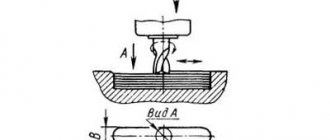
- Up and down milling.
If there are no small chips, the machines can process products made of non-ferrous metals. The desktop horizontal unit must not be used in cases with other metals that do not meet this requirement.
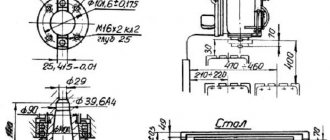
NGF-110sh3 Dimensions of the working space of the milling machine
Dimensions of the working space of the NGF-110sh3 milling machine
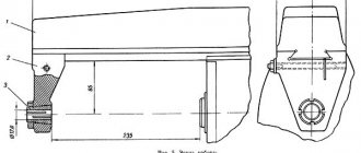
Sketch of a trunk with an earring of a horizontal milling machine NGF-110sh3
- trunk
- earring
- screw
- earring sleeve
- screw
The stand in the upper part has dovetail-type guides in which trunk 1 is installed. The trunk can be moved along the guides manually. The trunk is clamped to the guides using a wedge, which, when the screw is tightened, is tightened and secures the trunk to the stand.
An earring 2 is installed at the front end of the trunk. The earring on the trunk is tightened with a nut 5. Rearranging the earring from one machine to another due to individual adjustment is not allowed.
The bronze bearing-sleeve of the earring 4 has a conical outer surface and two longitudinal cuts, due to which the clearance in the bearing is adjusted with a nut 3.
Before starting work, it is necessary to lubricate the inner cavity of the earring bushing with I-30A oil.
The gap adjustment is determined by the heating of the shackle bushing (when running for one hour at maximum spindle speed, the heating of the bushing should not exceed 50-60 ° C, with sufficient lubrication).
The mandrel is designed for fastening cylindrical disk and other cutters.
The cutters are mounted on the mandrel using mounting rings and a nut.
To ensure the rigidity of the cutting tool, the free end of the mandrel is installed in the support of the shackle. The earring is attached to the trunk.
List and location of components
This equipment belongs to a variety of widely universal machines. For educational purposes, the technical characteristics can be called ideal. The machine contains the following components:
- Mandrel.
- Lighting is locally supplied from a separate source.
- A special plate on which electrical equipment is placed.
- Screen for protection.
- Trunk with earring.
- Vise.
- The speed box is mounted on a stand.
- Table for installing the sled.
- Console.
A standard push-button station is used for control. This simplifies operation and increases safety for users. Two additional levers are used to select the rotation speed of the spindle assembly. There are three flywheels, they were already mentioned earlier.
There are three directions in which the table moves:
- In a place with consoles, along the rack guides. This is vertical.
- In the case of longitudinal movement, the support is on the slide guides.
- Movement based on cantilever guides, if we are talking about a transverse plane. Then the work surface and the slide move simultaneously.
Three additional screws are provided to the table structure. Each of them has its own separate task:
- Clamping the slide on the console.
- Clamping with a slide directly on the working surface.
- Performing feed in the longitudinal direction.
Two nuts are suitable for simultaneously adjusting the feed lengthwise and crosswise.
The mandrel allows you to fix the workpiece, which is used together with the unit. A nut and several mounting rings allow you to connect the structure into a single whole. A mandrel is mounted into the earring support, with the other end. The earring support is installed in the trunk. Thanks to this device, the cutters remain as rigid as possible.
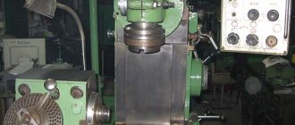
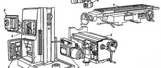
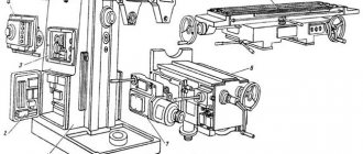
NGF-110sh3 General view of the universal milling machine
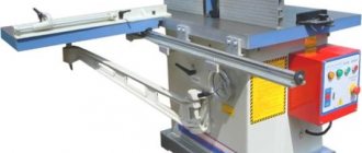
Photo of desktop milling machine NGF-110sh3
Photo of desktop milling machine NGF-110sh3
Photo of desktop milling machine NGF-110sh3
Photo of desktop milling machine NGF-110sh3
NGF-110sh3 Location of machine controls
Location of machine controls NGF-110sh3
List of controls for the milling machine NGF-110sh3
- handle, spindle speed switching
- handle, spindle speed switching
- longitudinal feed handwheel
- cross feed handwheel
- vertical feed handwheel
- push-button control station
General view and controls of a school metal cutting machine
NGF-110 is a single-column milling machine with a cast base in the form of a shaped plate. In the corners it has holes in the ears for fastening to the table, and horizontal adjustments during installation. In the front part there is a console with a table and sled. On top there is a round trunk with an earring. On the sides, a lamp with lighting and a protective screen are attached to the body.
The engine is located at the rear and is connected to the gearbox by a belt drive. It is turned on by buttons at the bottom of the machine. The spindle speed switching handle is on the side of the stand. On the slide and the end of the table there are flywheels with movement control handles. The table is raised vertically by a handwheel at the very bottom of the screw.
NGF-110sh3 Kinematic diagram of the milling machine
Kinematic diagram of the NGF-110sh3 milling machine
Rotation from electric motor I is transmitted by a V-belt transmission to gearbox shaft II (Fig. 7). Next from shaft II. rotation is transmitted to shaft III and then to spindle IV through gears 4, 5, 6, fixedly mounted on shaft II, movable triple and double gear blocks sitting on shaft III and gears 12, 13 fixedly mounted on spindle IV.
Movable gear blocks allow six different spindle speeds to be achieved (see spindle speed graph).
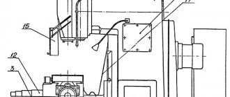
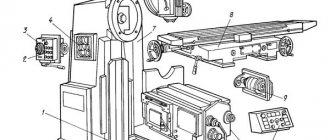
Design of a desktop horizontal milling machine NGF-110Sh1
Location of the main components on the NGF-110sh1 machine
Location of the main components on the NGF-110sh1 machine
Location of machine controls NGF-110sh1
Location of machine controls NGF-110sh1
The desktop horizontal milling machine consists of the following main components and parts (Fig. 1 and 2):
- 1. Bed with base;
- 2. Drive;
- 3. Gearbox with switching mechanism;
- 4. Console;
- 5. Longitudinal movement table;
- 6. Transverse movement carriage;
- 7. Vertical movement mechanism;
- 8. Reversing motor starter;
- 9. Trunk;
- 10. Mandrels for securing cutters;
- 11. Installation vise.
Bed with base
The bed is the simplest form of casting with four bored holes for the spindle, gear block shaft, drive shaft and trunk. At the bottom of the casting there is an internal solid jumper, which serves as an oil reservoir pan for lubricating the gears and bearings of the gearbox.
The base of the machine is a massive rectangular cast iron plate measuring 600 x 400 mm. The plate is intended for fastening the frame and installing the machine on the foundation.
Drive unit
Using a V-belt drive, rotation from the electric motor is transmitted to the gearbox drive shaft, which is mounted on three ball bearings. A gear is rigidly mounted on the shaft, transmitting rotation to the main shaft of the gearbox through a gear that is permanently coupled to it and mounted on the main shaft.
The electric motor is mounted on a hinged bracket 2 (Fig. 3). If the V-belt becomes loose due to its stretching, unscrew nut 5, tighten the belt with a second nut, and then screw nut 5 back on.
The belt drive is covered by a casing attached to the body.
The machine is started by a drum reversing switch type BP1-132.
The machine is connected to the electrical network through an input switch BB (batch switch for 25 A) type VP-25.
Grounding of the machine during installation, as well as its operation, is carried out in accordance with the requirements of the State Inspectorate for Industrial Energy under the Ministry of Energy of the USSR.
Gearbox with shift mechanism
The gearbox with shift mechanism consists of a main shaft with a rigidly mounted gear and a movable triple block and three gears sitting rigidly on the spindle. The shaft is supported by trunnions on ball bearings.
The spindle rotates in two supports. The gear block is moved by a special fork sitting on the shift lever.
When shifting, the gear unit occupies three operating positions, giving the spindle three different speeds, and in combination with a two-speed pulley, the spindle receives six speeds from 60 to 840 rpm.
The gear shift lever has a handle with a spring pin that locks the complete engagement of the gears in a certain position along the slots in the scale.
Switching speeds is carried out only when the machine is completely stopped.
There is a plate on the machine bed indicating the machine spindle revolutions per minute.
Console of milling machine NGF-110sh1
Console of milling machine NGF-110sh1
The machine console (Fig. 4) is a box-shaped casting on which the mechanisms for longitudinal, vertical and transverse movement of the table are mounted. The console is mounted on vertical guides with two straps, and is adjusted with a side wedge and two screws.
For longitudinal and transverse movement of the work table, the machine has a slide with dovetail-shaped guides. The slide is adjusted using wedges and screws. A table nut is fixed at the base of the longitudinal guide slide. The transverse movement of the table is carried out by a lead screw with a rectangular thread and a handle. The longitudinal movement of the table is carried out by a lead screw and handwheels, which are located on both sides of the table.
The lead screws have vernier bushings on both sides with a graduation value of 0.1 mm. There are three T-shaped grooves on the working surface of the table for securing a part or a vice.
To lift the table vertically, a lead screw is attached to the base of the machine. The lead screw nut is fixed at the base of the console. To rotate the lead screw, a handwheel is mounted on it.
Installation vise
The installation vise (Fig. 5) is the main device for fastening small parts of various profiles and can have replaceable jaws in the case of fastening parts of complex shapes.
For ease of use, the vice is made rotating. On the rotary dial there are divisions in degrees. The division value is 1°.
The vice is secured in the desired position with a locking bolt and nut.
Machine trunk and mandrel with cutter
The guides of the upper part of the frame (Fig. 6) accommodate the trunk of the machine with an earring, secured in the working position with a special clamp with a handle.
A ball bearing is mounted in the shackle, carrying the milling mandrel.
A cutter is fixed on the shaft between the mandrels. Depending on the work performed on the machine, the trunk can be installed at different distances from the console guides, i.e., with different reach.
Description of the main components of the NGF-110sh3 milling machine
Machine stand NGF-110sh3 with gearbox
The stand is the basic unit on which all other components and mechanisms of the machine are mounted.
The rigidity of the rack structure is achieved due to the developed base and the trapezoidal cross-section of the rack in height.
The rack is divided into two compartments. The gearbox is mounted in the upper compartment, and the electric motor is mounted in the lower compartment.
A three-shaft six-speed gearbox is mounted in the upper part of the rack housing and provides spindle speed control from 100 to 1000 rpm. The required rotation speed is selected using the switch levers located on the left side of the machine.
To inspect the gearbox, you must remove the side cover.
The spindle is a double-bearing hollow shaft.
The front journal of the spindle is supported by two angular contact bearings 8 (Fig. 2), and the rear journal is supported by radial bearing 9. To eliminate the axial clearance of the front bearings, two nuts 10 are installed on the spindle. Spacer rings 11 and 12 are installed between the bearings. When the bearings wear out the gap in them is eliminated by grinding the ends of the internal spacer ring 12. The compensation ring 13 is used to eliminate the axial play of the spindle.
Gearbox of milling machine NGF-110sh3
Photo of the gearbox of the NGF-110sh3 milling machine
Diagram of the gearbox of the NGF-110sh3 milling machine
- rack
- spindle
- oil indicator
- spline shaft
- drain plug
- pulley
- V-belt
Spindle speed chart for milling machine NGF-110sh3
Console
Table and console of the milling machine NGF-110sh4
Console of milling machine NGF-110sh4
The console is the basic unit of the feed mechanism. A table with a slide is installed on the console guides. Cross feed of the table is carried out from the cross feed screw 2. Vertical feed of the console along the guides of the rack is carried out from the vertical feed screw 3.
Desktop
Milling machine table NGF-110sh4
- table
- sled
- cross feed nut
- longitudinal feed nut
- longitudinal feed screw
- table clamp screw on the slide
The work table of the machine is the last element in the feed chain and has the ability to move in three directions: along the slide guides - longitudinally, together with the slide along the console guides - in the transverse direction, and together with the console along the rack guides - in the vertical direction.
Protective screen
A protective screen is installed on the machine to protect the worker from flying chips in the cutting zone.
Gearbox lubrication
Gear wheels and gearbox bearings are lubricated by splash lubrication.
I-30A oil is poured into the oil reservoir to a level controlled by the oil indicator.
Change the oil for the first time after 15 days of operation, then every 3 months.
Machine elements
The milling apparatus consists of the main elements:
- console;
- table with slide;
- protective screen;
- frame;
- stand with speed box;
- lamp;
- stove with electrical equipment;
- trunk.
The stand with the high-speed box of the NGF 110 milling machine is the main element of the entire machine. The stand has a base and is made in the form of a trapezoidal section. This ensures the necessary rigidity of the entire structure.
The gearbox along with the electric motor is fixed on the rack. The first is located at the top of the rack, the second is in the lower section. The box is equipped with 6 speed modes and has three shafts in its structure. The gearbox directly affects the spindle speed. Thanks to it, the spindle of the NGF 110 apparatus is able to make more than 1240 revolutions per minute.
The console, like the stand, is the main element of a metal machine. The table along with the slide is fixed on it. The cross drive screw provides transverse feed of the table, and the vertical feed screw produces vertical feed of the console.
The trunk is fixed in the upper part of the apparatus stand and clamped with a wedge.
The frame secures the instrument. The instrument is connected to the frame using a nut and rings. Due to the frame, the required rigidity of the cutters is achieved.
The machine is equipped with an asynchronous type electric motor. It has three phases and is short-circuited. The engine is located in the lower compartment of the rack. The electrical equipment of the unit includes a magnetic starter with blocks and a transformer. These elements are located in a special machine plate. Any milling unit is equipped with a lamp.
Electrical diagram of the NGF-110sh3 milling machine
Electrical diagram of the milling machine NGF-110sh3
The electrical equipment includes: a three-phase squirrel-cage asynchronous electric motor installed in the lower compartment of the rack, and machine plates installed in isolated niches, a magnetic starter, terminal blocks, switches, and a push-button control station.
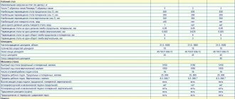
Technical characteristics of machine models
| Parameter name | NGF-110sh3 | NGF-110sh4 |
| Basic machine parameters | ||
| Main dimensions GOST, TU | TU-79 RSFSR 355-72 | TU 79 RSFSR 441-79 |
| Accuracy class according to GOST 8-82 | N | N |
| Dimensions of the working surface of the table (length x width), mm | 100 x 400 | 100 x 400 |
| Distance from the axis of the horizontal spindle to the table, mm | 30..200 | 30..200 |
| Distance from the axis of the horizontal spindle to the trunk, mm | 85 | 85 |
| Distance from the end of the spindle to the suspension bearing (earring), mm | 235 | 235 |
| The largest diameter of the cutter installed on the machine, mm | 110 | 110 |
| Desktop | ||
| Maximum table longitudinal movement, mm | 250 | 250 |
| Maximum transverse movement of the table, mm | 85 | 85 |
| Maximum table movement vertical, mm | 170 | 170 |
| Number of T-slots | 1 | 1 |
| Movement of the table by one division of the longitudinal dial (one revolution), mm | 0,05 (4) | 0,05 (4) |
| Movement of the table by one division of the transverse dial (one revolution), mm | 0,05 (4) | 0,05 (4) |
| Movement of the table by one division of the vertical dial (one revolution), mm | 0,025 (2) | 0,025 (2) |
| Rapid table travel longitudinal/transverse/vertical, mm/min | No | No |
| Number of table feed stages | No | No |
| Limits of working mechanical table feeds. Longitudinal, transverse, vertical, mm/min | No | No |
| Table rotation angle (in the extreme forward position), degrees | No | No |
| Spindle | ||
| Horizontal spindle rotation speed, rpm | 100, 160, 250 ,490, 630, 1000 | 125, 200, 310, 500, 800, 1250 |
| Number of horizontal spindle speeds | 6 | 6 |
| Inner taper of horizontal spindle | Morse 3 | Morse 3 |
| Drive and electrical equipment | ||
| Number of electric motors on the machine | 1 | 1 |
| Main motion drive electric motor, kW (rpm) | 0,6 (1410..1440) | 0,55..0,75 (1390..1480) |
| Dimensions and weight of the machine | ||
| Machine dimensions (length x width x height), mm | 685 x 640 x 790 | 685 x 640 x 925 |
| Machine weight, kg | 200 | 340 |
- Tabletop horizontal milling machine NGF110Sh4. Operating manual, 1984
- TU 79 RSFSR 441-79
- Avrutin S.V. Fundamentals of Milling, 1962
- Avrutin S.V. Milling, 1963
- Acherkan N.S. Metal-cutting machines, Volume 1, 1965
- Barbashov F.A. Milling business 1973, p.141
- Barbashov F.A. Milling work (Vocational education), 1986
- Blumberg V.A. Milling machine handbook, 1984
- Grigoriev S.P. Practice of coordinate boring and milling work, 1980
- Kopylov R.B. Working on milling machines, 1971
- Kosovsky V.L. Handbook of a young milling operator, 1992, p. 180
- Kuvshinsky V.V. Milling, 1977
- Nichkov A.G. Milling machines (Machinist's Library), 1977
- Pikus M.Yu. A mechanic's guide to repairing metal-cutting machines, 1987
- Plotitsyn V.G. Calculations of settings and adjustments of milling machines, 1969
- Plotitsyn V.G. Setting up milling machines, 1975
- Ryabov S.A. Modern milling machines and their equipment, 2006
- Skhirtladze A.G., Novikov V.Yu. Technological equipment for machine-building industries, 1980
- Tepinkichiev V.K. Metal cutting machines, 1973
- Chernov N.N. Metal cutting machines, 1988
- Frenkel S.Sh. Handbook of a young milling operator (3rd ed.) (Vocational education), 1978
Bibliography:
Related Links. Additional Information
- Milling machines: general information, classification, designation
- School lathes. Review
- Comparative characteristics of cantilever milling machines of the 6N, 6M, 6R, 6T
- Feed box for console milling machines of the 6M : 6M12P, 6M13P, 6M82, 6M83, 6M82Sh, 6M83Sh
- Feed box for console milling machines of the 6P : 6P12, 6P13, 6P82, 6P83, 6P82Sh, 6P83Sh
- Feed box for console milling machines 6T : 6T12, 6T13, 6T82, 6T83, 6T82Sh, 6T83Sh
- Milling machine repair technology
- Adjustment of milling machines
- Friction clutch. Friction shaft. Friction clutches in metal-cutting machines
- Automatic cycles of milling machines (6P12)
- Testing and checking metal-cutting machines for accuracy
- Directory of universal milling machines
- Manufacturers of metal-cutting machines in Russia
- Manufacturers of milling machines in Russia
Home About the company News Articles Price list Contacts Reference information Interesting video KPO woodworking machines Manufacturers