Specifications
A homemade dividing head must have certain technical characteristics, among which we note:
- maximum diameter or overall dimensions of the workpiece. This parameter is quite important. It should be taken into account when creating a homemade dividing head. the maximum diameter is indicated for turning equipment, for milling equipment the width, length and height are indicated, that is, linear dimensions;
- worm pair ratio;
- replacement wheel diameter;
- output spindle diameter;
- diameter of the cartridge used;
- the price of one division of the dial. A dial is necessary to rotate the workpiece by a certain degree. The division value indicates the accuracy of the equipment;
- maximum width of keys. Milling equipment is often used to create dowels on a surface. A homemade dividing head is needed to form several keys;
- weight of the structure. This parameter determines the difficulty of using the structure.
Dividing head device
It is worth considering that a homemade dividing head can have varying degrees of accuracy.
DIY dividing heads
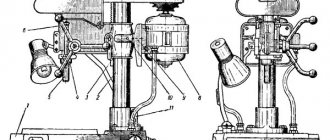
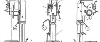
The functionality of a milling machine can be significantly increased by using special equipment called a dividing head.
It is used in the production of complex parts, as it allows the workpiece to be rotated by a certain degree, which is set by the machine operator.
When purchasing a lathe or milling machine, you can count on the equipment being included. In some cases, you can do it yourself.
Homemade dividing head
Classification
There is a certain classification of the system for shifting the workpiece at a certain angle:
- Simple - This design option is quite simple to create, easy to set up and use. The main elements can be called the spindle on which the workpiece is attached, and the second is the dial, which has several holes on the surface. The design is simple and reliable, but cannot be used to obtain ultra-precise parts.
- Combined - control is performed using a handle. The number of presses affects how much the workpiece deviates from the central axis. The combined version is used in the production of complex devices.
- Universal - this device is a complex technological complex, which is controlled by a handle and a dividing disk. The design has several gear systems. In some cases, this DG is called differential.
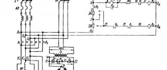
Scheme of motion transmission with the differential division method Kinematic diagram when configured for cutting helical grooves Kinematic diagram when configured for differential division Kinematic diagram of the dividing head of simple division
The above points should be taken into account when considering which device can be used for processing workpieces.
A homemade dividing head must have certain technical characteristics, among which we note:
- maximum diameter or overall dimensions of the workpiece. This parameter is quite important. It should be taken into account when creating a homemade dividing head. the maximum diameter is indicated for turning equipment, for milling equipment the width, length and height are indicated, that is, linear dimensions;
- worm pair ratio;
- replacement wheel diameter;
- output spindle diameter;
- diameter of the cartridge used;
- the price of one division of the dial. A dial is necessary to rotate the workpiece by a certain degree. The division value indicates the accuracy of the equipment;
- maximum width of keys. Milling equipment is often used to create dowels on a surface. A homemade dividing head is needed to form several keys;
- weight of the structure. This parameter determines the difficulty of using the structure.
Dividing head device
It is worth considering that a homemade dividing head can have varying degrees of accuracy.
When considering a homemade version, the following points should be taken into account:
- The device has a low cost due to the use of used elements.
- All work can be done independently without using the services of a qualified specialist.
- The reliability of the device can depend on many things. When performing work, you should control the quality of assembly at every stage
- You can use a homemade version only when producing a small number of parts, the accuracy of which is less.
- Maintainability can be called an advantage of the device.
The disadvantages include the fact that the design does not allow obtaining parts of high quality and dimensional accuracy.
In conclusion, we note that the cost of the industrial version is quite high, but it also lasts much longer than home-made equipment. Only with certain experience can you create a homemade dividing head.
Dividing head UDG (universal).
| The dividing head UDG (universal) is an integral accessory of a milling machine. Like machine tools, dividing heads are required to ensure high accuracy, ease of use and maintenance, and durability. Universal dividing heads of the UDG-D type are used with universal and horizontal milling machines and are intended for various milling, hobbing, boring, drilling, marking and other similar works. |
| UDG-D-160 | UDG-D-200 | UDG-D-250 | UDG-D-320* | UDG-D-400 | |
| Largest part diameter, mm | 160 | 200 | 250 | 320 | 400 |
| Diameter of 3-jaw chuck, mm | 100 | 125 | 160 | 160 | 200 |
| Center height, mm | 85 | 105 | 130 | 165 | |
| Distance from the base to the end of the spindle in its vertical position, mm | 180 | 235 | 280 | 350 | 450 |
| Division range | 2-400 | 2-400 | 2-400 | 2-400 | 2-400 |
| Gear ratio | 1:40 | 1:40 | 1:40 | 1:40 | 1:40 |
| Spindle hole diameter, mm | 14,9 | 20,2 | 26,5 | 38,2 | 38,2 |
| Thread of the working end of the spindle, mm | 33x2 | 39x3 | 52x3 | 60x4 | 76 |
| Front spindle Morse taper | 2 | 3 | 4 | 5 | 5 |
| Spindle rotation angle in the vertical plane, gr. | |||||
| down from the center line | 5 | 5 | 5 | 5 | 5 |
| up from the center line | 95 | 95 | 95 | 95 | 95 |
| Width of guide keys, mm | 12 | 14 | 18 | 18 | 22 |
| Overall dimensions of the base | 212x156 | 260x180 | 260x180 | 290x234 | 290x234 |
| Weight, kg | 35,5 | 50 | 53,5 | 101 | 106 |
*
The UDG-D-320 dividing head has a different designation - UDG-N-160A.
| Accessories for the universal dividing head UDG-D-250 (UDG-D-250-A) are designed for differential dividing and milling of spiral grooves. |
Complete set of universal dividing head UGD:
| 1. Steady rest - 1 pc. 2. Guitar for differential division - 1 pc. 3. Guitar for cutting spirals - 1 pc. 4. Mandrel for differential division - 1 pc. 5. Gear wheels, set - 1 pc. 6. Passport of accessories for UDG - 1 pc. | Gear set: z=25; m=1.5 - 2 pcs. z=30; m=1.5 — 1 piece. z=35; m=1.5 — 1 piece. z=40; m=1.5 — 1 piece. z=50; m=1.5 — 1 piece. | z=55; m=1.5 — 1 piece. z=60; m=1.5 — 1 piece. z=70; m=1.5 — 1 piece. z=80; m=1.5 — 1 piece. z=90; m=1.5 — 1 piece. z=100; m=1.5 — 1 piece. |
The device of dividing heads
The purpose of the dividing head is to periodically rotate the workpiece at specified equal and unequal angles or continuously rotate the workpiece
When working on milling machines, dividing heads are intended for milling grooves of various profiles (both straight and spiral) on cylindrical and conical workpieces. By appropriately adjusting the dividing head, any number of grooves can be placed around the circumference of the workpiece.
Dividing heads are mainly used on horizontal milling machines. For universal milling machines they are a mandatory accessory; They are supplied to simple horizontal milling machines only upon special customer request.
The following types of dividing heads are distinguished:
- simple - for direct division,
- universal,
- optical.
In order to increase labor productivity in large-scale and mass production, multi-spindle dividing heads are used.
Simple heads
for direct division, they are distinguished by their simplicity of design and ease of control. They are used primarily for processing relatively simple parts produced in large quantities.
In the body of a simple dividing head there is a spindle, the front end of which is used to secure the workpiece; At the rear end of the spindle, a dividing disk (limb) is attached, which has a certain number of grooves on its circumference; heads of this type provide the ability to divide the workpiece into a limited number of equal parts - 2, 3, 4, b, 8, 12 and 24, which is determined by the number of grooves on the dividing disk. However, when manufacturing a special dividing disk, such a head can be adapted for other numbers of divisions, as well as for dividing into unequal parts. The angle of rotation of the spindle is measured directly from the dividing disk.
Heads for direct division are made horizontal (with a horizontal spindle) and vertical (with a vertical spindle). The latter are equipped with a three-jaw chuck, in which the workpiece is usually secured.
Universal dividing heads
(UDG) have a more complex design and are used in single, small-scale, experimental and, less commonly, mass production. They are widely used in the repair shop, and especially in the tool shop. In the domestic industry, universal dividing heads of the UDG-D160, UDG-D200, UDG-D250, UDG-D320, UDG-D400 models are used, as well as heads produced since 1980 (GOST 8615-80) with the following designations: 7036-0051; 7036-0061; 7036-0052; 7036-0062; 7036-0053; 7036-0063;7036-0054; 7036-0064; 7036-0055; 7036-0065; 7036-0056; 7036-0066.
Optical dividing heads
are used for accurate readings of the angles of rotation of workpieces: in the manufacture of multi-blade cutting tools, dividing disks of mechanical devices and other precision parts, mainly instrumental, in the production of markings on scales.
Dividing head accessories
. The UDG accessories include a tailstock, two replacement wheels, a front center with a leash, a jack, special and universal linings, a three-jaw chuck and mandrels for securing parts.
In Fig. IX.7, and the tailstock device is shown. Its body 1 is located in a deep groove in the base 8. Raising and lowering the body is carried out after releasing the nuts of the coupling bolts 4 by rotating the hexagonal head 9, the toothed shaft 7, coupled with the roller-rack 6, the upper end of which is connected by a pin 5 to the body 1.
| After installing the housing in the required position, it is secured to the base of the headstock with bolts 4. The movement of the ninole 3 is carried out by rotating the handwheel of the screw 2. When milling conical parts fixed in the centers, the axis of the tailstock zero point must coincide with the axis of the inclined spindle of the dividing head. In such cases, a special tailstock is required (Fig. IX.7, b), the quill of which can be raised to a greater height and installed at a greater angle to the table plane than the headstock quill in Fig. IX.7, a. Rice. IX.7. UDG tailstocks: a - main tailstock (main cuts); b - special tailstock with a large range of center height adjustment |
Guitars of replacement wheels used in differential division and milling of helical grooves are shown respectively in Fig. IX.4 and IX.5.
In Fig. IX.8 shows the accessories of the dividing heads. The spindle roller used for differential division (Fig. IX.8, a) is secured in the spindle hole by tightening screw 2 of the conical plug 1, which expands the conical part of the roller due to the three through grooves 17 in it. Front center 3 (Fig. IX .8, b) with driver 4 is installed in the conical socket of the spindle. The center cone at its apex should have an angle of 60°. At the right end of the center there is a threaded hole for screwing in a rod (rod), through which the center is secured in the spindle of the dividing head
The jack (Fig. IX.8, c) is used to support non-rigid workpieces. The round workpiece is located in the prismatic recess of the adjustable head 7 of the jack.
Height adjustment is carried out by screwing or unscrewing the screw 5. The position of the head 7 is fixed by screwing in the locking screw 6.
| Clamp 8 (Fig. IX.8, d) is fixed on the workpiece being processed when it is installed in the centers. The bent end is inserted into the groove of the driver 4, which transmits spindle rotation to the workpiece. The rigid center mandrel (Fig. IX.8, e) and the cantilever mandrel (Fig. IX.8, f) are designed for securing workpieces that have holes as a base. The rigid mandrel is installed in the centers of the head and its tailstock, and the cantilever mandrel is installed in the conical socket of the head spindle. The rotary plate (Fig. IX.8, g) is used in cases where the axis of the dividing head must take a position at a certain angle to the direction of the longitudinal feed of the machine table. Fig.IX. 8. Main accessories of dividing heads |
UDG-160 Location of dividing head controls
List of controls for the dividing head UDG-160
- 2. Handle with lock. Fixing the dividing disk
- 7. Stopper. Locking the dividing disk
- 8. Latch. Fixing the direct division dial
- 19. Nut. Fastening the head housing to the base
- 23. Clamp. Spindle lock
- 24. Handle. Turning the worm on and off
- 27. Sliding sector. Counting holes on the dividing disk
- 36. Handwheel. Moving the tailstock quill
- 41. Nut. Sector fastening
- 42. Screw. Leash attachment
- 43. Screw. Attaching the indexing disc clamp assembly
- 44. Shank. Guitar mount
- 45. Nut. Tailstock quill fastening
- 46. Gear head. Moving the tailstock vertically
- 47. Bolt. Tailstock housing mount
- 48. Nut. Fastening the bar with handle and lock
Information about the manufacturer of dividing heads UDG-135 (UDG N-135)
The developer and manufacturer of dividing heads UDG-135 (UDG N-135) until 1990 was the Leningrad optical-mechanical association LOMO .
Currently, the production and sale of universal dividing heads UDG-160 (UDG-D-160), UDG-200 (UDG-D-200), UDG-250 (UDG-D-250), UDG-320 (UDG-D- 320) is carried out by Production , which was founded in 1990 on the basis of OJSC LOMO.
Products manufactured by the Leningrad Optical-Mechanical Association LOMO
- UDG-100 (UDG N-100)
- universal dividing head 100 (Ø 200) - UDG-135 (UDG N-135)
- universal dividing head 135 (Ø 270) - UDG-160 (UDG-D-160)
- universal dividing head Ø 160 - UDG-200 (UDG-D-200)
- universal dividing head Ø 200 - UDG-250 (UDG-D-250)
- universal dividing head Ø 250
BORING FROM MILLING
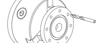
The functions of a boring machine can also be successfully performed by a milling machine. Of course, in a lower accuracy class, but for many jobs this is not so significant. For such a transformation, we recommend that you use the universal boring head developed at the Valuyskaya station for young technicians: it impresses with its manufacturability and simplicity.
The device consists of the following elements: conical shank, hub and quill. The hub is mounted on the shank with four screws, two of which clamp the quill in parallel. The cutter is fixed in a slider that moves along two cylindrical guides located inside the quill. The slider is moved using a lead screw.
Boring head for milling machine:
1—shank with Morse taper (steel 45), 2—M6 screw, 3—hub (steel 45), 4—lead screw (steel 45), 5—sleeve (BrOTsS-4-4-17), 6—lock nut ( steel 20), 7 - slider (steel 45), 8 - M6 screw, 9 - guide (steel 45), 10 - plug (BrOTsS-4-4-17), 11 - quill (steel 45), 12 - washer, 13 — M6 screw, 14 — boss (steel 45), 15 — handle (steel 20).
The boring head works as follows. The tail part is inserted into the spindle of the milling machine and secured with a standard tightening screw. The workpiece is fixed in a vice or on the machine table. When boring holes with a diameter of up to 40 mm, the position of the cutter relative to the center of the hole is adjusted only. due to the extension of the slider. Boring of holes with a diameter of up to 85 mm is carried out in two steps. First, as described above, then the slider should be moved to its original position, loosen the clamping screws and move the quill until it stops at the hub.
Control the hole diameter using a scale marked on the end surface of the bushing (item 5). The kit also includes a handle for the lead screw and clamping screws.
Y. KUTEPOV, Valuyki
Noticed a mistake? Select it and press Ctrl+Enter to let us know.
modelist-konstruktor.com
Division methods
Division using a milling machine can be carried out using several methods, among which we note:
- Direct division is carried out without the use of an intermediate mechanism. For this purpose, a device with simple optical division is used.
- Simple division is used quite often, in which a stationary disk is used. This cutting method is carried out using UDG, which makes the scope of application wide.
- Combined division is also carried out using a dividing head.
- The differential method is also carried out on universal dividing heads, which have an additional set of replaceable gears.
- The continuous method is implemented by optical and universal heads, which have a kinematic connection between the spindle head and the longitudinal feed screw of the milling machine.
Kinematic diagram of a simple division dividing head
These methods relate to the milling machine on which the equipment in question can be installed.
Kinematic diagram when configured for differential division
Kinematic diagram when setting up for cutting helical grooves
Advantages
Using a dividing head, when working on metal on a milling machine, the following additional functionality can be distinguished:
- significantly expand the range of work operations;
- process a workpiece that is located in a convenient or desired position relative to the table plane, both vertically and horizontally;
- simplify metal work with workpieces of various sizes.
to menu
Classification
Universal dividing heads have their own designation, by which their main operating parameters can be determined:
- UDG 100 - processed workpieces with a diameter of 100 mm, dimensions at the base - 260x180 mm, weight - 25 kg;
- UDG 125 - it can be used to process workpieces whose maximum diameter does not exceed 125 mm. Base dimensions - 260x180 mm. Weight - 28 kg;
- UDG 250 - the maximum permissible diameter of the workpiece being processed is 250 mm, dimensions - 260x180 mm, weight - 53.6 kg;
- UDG 320 - the workpiece should not exceed 320 mm in diameter, base dimensions - 290x234 mm, weight - 101 kg;
- UDG 400 is the largest dividing head, which allows you to work with workpieces with a cross-section of up to 400 mm. Overall dimensions of the base - 290x234 mm, weight - 106 kg.
All of the above devices have a division value on the dial of 15º.
Universal dividing head UDG-250
Many parameters are the same, since the use of these devices is designed for standard equipment. The difference is mainly in the diameter of the parts being processed - the larger it is, the larger and heavier the device.
Another type of notation is used. For example - UDG 40 D250. This means that the dividing head is universal; for a full revolution of the spindle, you need to turn the handle 40 times, the maximum diameter of the workpiece should not exceed 250 mm. to menu
Optical dividing head
Such a device is used to perform particularly precise divisions, and in some cases, to check the correctness of the division performed on another device.
At the top of the head there is a microscope eyepiece, in the optical system of which a fixed scale is placed. The division price in it is 1′, and the total number of parts is 60. The divisions are visible so clearly that counting a fraction of ¼ minutes is not difficult at all.
The spindle rotation angle is calculated in the same way as for a mechanical head. But it should be noted that it is necessary to make a table of all successive angles, since they are summed up. to menu
Homemade dividing head
For small amounts of metal work done by hand, it makes no sense to buy expensive additional equipment, since the investment will never pay off.
Homemade dividing head
But home craftsmen who have a milling machine at their disposal still need such a device as a dividing head. To create it, you will need a worm gear, a lathe chuck with a diameter of about 65 mm, and a disk (limb).
The layout of these elements is standard; nothing new needs to be invented. The divisions (holes) on the disk are made to suit your individual needs. Everything else is similar to the industrial options.
After assembling the homemade structure, it is necessary to adjust it. This is done after the part made on a milling machine using a homemade dividing head is compared in terms of parameters with the factory sample. to menu
Additional Information
The use of different types of milling heads allows you to process parts on one machine, while without their use, it is necessary to use several. There is additional equipment for milling machines in the form of the following types of heads:
- corner;
- boring;
- slotting.
In turn, they can be manufactured in several versions, for example, with replaceable knives or plates.
Semi-universal dividing head HOMGE BS-0
The angular head also has several design options:
- 90º head:
- modular type;
- universal.
All these additional devices (angular, boring, slotting heads) significantly increase the accuracy and increase the productivity of milling equipment, as they allow vertical and horizontal processing, as well as work at an angle, without reinstalling the workpiece.
data-full-width-responsive=”true” data-ad-client=”ca-pub-8514915293567855″data-ad-slot=”8040443333″>
Method of working with the dividing head UDG N-135
Control circuit of the universal dividing head UDG 135
To work with a universal dividing head, you must first understand the control scheme (Fig. 4. 5). the explanation of which is given in table. 3.
Adjusting the gearing of the worm pair in the dividing heads UDG N-135 and UDG H-160
The gap formed due to wear of the worm pair can be a source of error when working with the dividing head. Therefore, it is important to timely adjust the worm gear engagement
When a gap forms in the axial direction, it is necessary to turn the handle 26 (Fig. 6) to disengage the worm from engagement with the worm gear, loosen the locking screw 54 and tighten the nut until the gap is completely eliminated, then re-fasten the nut with the locking screw and engage the worm in engagement with the gear.
The adjustment is checked by slightly turning the spindle in both directions. In this case, no axial movements of the worms should be observed.
If a gap forms in the engagement of the worm pair, it is necessary to remove the cover 55, loosen the screws 56, tighten the stoppers 57 until the gap is eliminated, then tighten the screws and put the cover in place.
Adjusting the gearing of the worm pair in the dividing head UDG N-135
Location of the main components of the universal dividing head UDG 135
Adjusting the gearing of the universal dividing head UDG 135
To eliminate the gap in the engagement of the worm pair, it is necessary to unscrew the nut 58 (Fig. 7), release the nut 59 with the stopper, turn the eccentric sleeve using the handle 60 to eliminate the gap, fix the position of the sleeve with the nut 59 with the stopper and secure the nut 58.
Next, by rotating the locking handle 2 (Fig. 2), you should make sure that the worm and worm gear rotate smoothly.
To eliminate the gap that may form in the axial direction, you need to loosen nut 48 (Fig. 5), remove the locking handle 2 (Fig. 2), the cap and tighten the two nuts.
Direct division
Direct division is used when dividing a circle in degrees, as well as by a frequently used number of parts, for example 3, 4, 6, etc.
When dividing a circle in this way, it is necessary first of all to turn handle 26 (Fig. 3) 180° to disengage the worm from engagement with the worm gear.
The spindle is rotated by rotating the direct division dial OR the chuck by hand. After each installation to the required angle, the spindle must be secured by turning handle 25.
When dividing into parts, the calculation is made using the formula:
n = 360°/α
where: n - number of parts;
α is the spindle rotation angle.
Simple division
A simple division of the circle into equal and unequal parts is done using a locking handle. The amount of rotation of the handle is measured by the holes on the dividing disk and is fixed with a locking rod.
The gear ratio of the worm pair is 1:40; it follows that for one revolution of the locking handle, the spindle, together with the workpiece, will rotate 1/40 of a revolution. Therefore, the number of revolutions of the locking handle
n = 40/z
where z is the number by which you want to divide the workpiece.
Example 1
It is necessary to mill 4 grooves. Determine the number of turns of the locking handle.
n = 40/z = 40/4 =10
The number 10 indicates that after milling each groove, the locking handle must be turned 10 full turns.
If, during the calculation, the number of revolutions of the locking handle turns out to be a fraction, then it must be converted so that the denominator of the fraction is equal to the number of holes in one of the circles on the dividing disk.
Example 2
It is required to cut a gear with a number of teeth of 18. Determine the number of revolutions of the locking handle.
n = 40/z = 40/18 = 2 (2/9) = 2 (12/54)
The number 2 · (12/54) shows that after cutting each tooth, the locking handle must be turned two full turns and 12 holes on a circle with the number of holes 54.
To install the locking handle to the required circumference of the dividing disk, you need to unscrew nut 48 (Fig. 5), move the locking handle and re-fasten the nut.
Example 3
It is required to mill a bolt head that has 6 edges. Determine the number of revolutions of the locking handle.
n = 40/6 = 6·(2/3)
The number 6 · (2/3) indicates that the locking handle must be turned 6 full and (2/3) turns. In order to turn the handle by (2/3) of a turn, it is necessary to select a circle on the dividing disk whose number of holes would be a multiple of 3, for example, 21, 30, 54. If you take a circle with 30 holes, then multiply the numerator and denominator by 10. we get:
n = 40/6 = 6·(2/3)·10/10 = 6·(20/30)
Therefore, after milling each face of the bolt, the locking handle must be turned 6 full turns and 20 holes from a circle with 30 holes.
For the convenience of readings, the dividing disk has a sliding sector 28 (Fig. 2). The sector is installed after the circle has been determined and the number of holes has been found to which the locking handle should be moved.
The sector consists of sliding rulers 61 (Fig. 8), a clamping screw 62 for fastening the rulers at the required angle, and a spring 63 that keeps the sector from arbitrary rotation.
When counting the holes between the rulers, you should remember that their number should be one more than the number obtained by counting.
The sector must be rotated immediately after moving the locking handle so that it is always in the position for the next division.
Having brought the locking handle to the required hole, you should remove the lock from the fuse and lightly tap the handle to bring it to the hole into which it will fit under the action of the spring.
If the locking handle is moved beyond the required hole, it is moved back a quarter or half a turn and again brought to the corresponding hole. The locking handle should always be rotated in the same direction.
The number of revolutions of the locking handle for dividing into any number of parts from 2 to 51 is given in table. 4, for division by the number of parts from 51 to 400 - in table. 5.
Differential division using a universal dividing head
Kinematic diagram of the universal dividing head UDG 135
From the table 13 it can be seen that the dividing disks do not allow division by all the necessary numbers. This mainly applies to prime numbers that cannot be factorized, for example 51, 61, 67, 73, etc., which are not on the dividing disks. In this case, the methods of direct, simple and combined division provide only an approximate solution, which is not always acceptable for practical use. To divide by numbers 51, 61, 67, 73, etc., the differential division method is used.
From the kinematic diagram for setting up differential division (Fig. 55) it is clear that the transmission of motion to the spindle occurs, as with simple division, i.e. from handle 4 through spur gears z2, z1 worm zG, worm wheel zk to spindle 1. Then from the product spindle through a set of replaceable gears zA, zB, zC, zD, installed on pins 5, and bevel gears z3, z4, the rotation is communicated to the dividing disk 3, and the stopper 2, braking the dividing disk, must be released. Thus, the amount of rotation of the spindle will be the result of the angles of rotation of the drive handle relative to the disk and the dividing disk itself, along which the handle is fixed (indexed). There can be two cases:
- the directions of rotation of the handle and the dividing disk coincide;
- The rotation of the handle and the rotation of the disk have different directions.
If denoted by:
- nр — revolutions of the disc handle with a lock;
- nd — revolutions of the dividing disk;
- nш - spindle revolutions
then if the directions of rotation of the handle and the disk coincide, psh = nр + nd, and if the directions of rotation do not coincide, nsh = nр - nd.
In general, the calculation formula can be presented as follows:
nsh = nр ± nd (16)
Since the required number of divisions z cannot be obtained on existing disks, an arbitrary (fictitious) number of divisions z'f, close to the required one, is accepted for calculation.
The number of spindle revolutions in the general case is determined in the same way as with simple division, nш = N/z, or, if N = 40, n = 40/z.
The number of turns of the handle corresponds to the setting for the number of divisions zf; nр = 40/zф. Consequently, the amount of rotation of the dividing disk, which is like an additional rotation, is determined from the formula
± nд = 40/zф - 40/z = 40/zzф·(zф - z)
For additional rotation of the dividing disk when turning the spindle by 1/z part, i.e. by one division, the guitar of interchangeable gears is adjusted. The transmission of rotation to the dividing disk (Fig. 54) can be represented as follows:
± nd = 1/z (zA zC)/(zB zD) z3/z4
or
± nd = 1/z·i·(25/25)·i/z,
where i = (zA·zC) / (zB·zD) is the gear ratio of the guitar’s replaceable gears.
Solving this equation for i, we obtain the calculation formula for setting up differential division for a universal dividing head with characteristic N = 40
From the formula it is clear that if the taken fictitious number zf is greater than the desired z, then the gear ratio i has a positive value. In this case, the direction of additional rotation of the dividing disk coincides with the direction of rotation of the handle. If zf> z, then the directions of rotation of the handle and the dividing disk do not coincide. These conditions must be especially taken into account when setting up guitar replacement gears.
40/zzф·(zф - z) = i/z
or
i = 40/zф·(zф - z)
Why are universal dividing heads needed?
In their own design, these are machine-made horizontal devices. They are equipped with jig boring and milling machines (semi-automatic). Thanks to them, any workpiece can be rotated for specific division angles. The workpiece itself is placed directly into the chuck. The use of these accessories guarantees the master obtaining the correct geometric shapes and precisely specified dimensions of all processed parts.
The use of these devices is especially effective when milling tooth cavities, cutting them in gear wheels, during the processing of polyhedra and the production of many types of different tools (countersinks, drills, special equipment). When cutting spiral-shaped grooves using heads, continuous rotation is carried out, as well as simultaneous feeding of workpieces along the axis.
Homemade dividing head for a lathe
» Machine » Boring head for milling machine
Boring work, the main purpose of which is to give existing holes the required parameters, can be performed using boring, milling and turning machines. Such work (for example, primary processing of a previously created hole or shifting its position relative to the axis) is performed only after the final completion of drilling (or reaming).
Boring work performed on a milling machine requires special tools. So, they can be either multi-blade (multi-cutting) or milling cutters, which are constantly rotating bodies during operation, covered with both wear-resistant and durable teeth. Milling cutters are one of the most important tools that allow processing of metal surfaces and are very diverse.
In fact, a boring head is a piece of special equipment, the main purpose of which is to hold the teeth described above (or cutters, depending on the choice of the main work tool) when using them to perform drilling, boring or other operations (milling).
Setup and Application
Before you start using the separating head, you should select it correctly. To do this, the master should consider several points.
- Product parameters. Elements thanks to which it is attached to the frame.
- Direction for using the tool:
- piece repairs and restoration – a universal type;
- high-precision work – optical;
- work on the flow - a simplified view of the head.
- Value for money. Payback.
- Demand for the brand.
The transitions that are made by the heads of the milling machine are directly dependent on the type of device, as well as on the characteristics that are set in accordance with the division of the scale. Setting up a device involves determining the volume of a sector of a circle.
Step-by-step adjustment of the milling machine head:
- converting 360 degrees of the diameter of a circle into the required number of divisions on sectors;
- determination of the sine of the angle obtained as a result of the calculation;
- rotate the device disk to the desired angle;
- clamping the unit body with a handle or clamping mechanism, as well as installing the working tool.
You can calculate the required division angle using the formula offered by the manufacturer's instructions. After this, the part must be secured to the machine frame, carrying out the longitudinal feed of the table. In this way the necessary operation is performed. The feed step is directly dependent on the nature of the processing. When a tooth is formed, it will be equal to the distance between the cavities of adjacent teeth.
To increase work productivity, at the end of each work cycle, the table and workpiece are returned to their original position faster. The fixation procedure relative to the selected hole on the measuring disk is carried out by springs. Thanks to the use of dividing heads of different types, craftsmen can process parts using one machine. Otherwise, you will have to use several units. The heads, in turn, can have replaceable legs or plates.
Additional devices in the form of dividing heads can increase the accuracy and productivity of milling equipment. They can be used for vertical and horizontal processing, as well as working at a given angle. In this case, the master does not have to reinstall the workpieces.
For information about dividing heads for milling machines, see the video below.
Setting up dividing heads
Possible tool transitions depend on the type of device and its technical parameters. The processing accuracy is determined by the divisions of the existing scale, the indicators of which correspond to the 7th (GOST-1.758) or 9th (GOST-1.643) calibration level.
The main setup process is to determine the dimensions of the pitch circle sector. In addition, the diameter of the circle and the number of compartments into which it is divided are taken into account.
The element configuration process consists of the following steps:
- Transform 360 degrees of full diameter into the required number of divisions by sector.
- The sine of the resulting calculated angle is determined.
- The device disk is set according to this indicator.
- The block body is fixed using a handle or a clamping mechanism, after which the working part of the tool is mounted.
The formula for calculating the required angle can be found in the UDG operating manual. The workpiece being processed is fixed on the machine mandrel, the table is longitudinally shifted, and finishing is performed. The feed pitch is affected by the type of processing. To increase productivity, after completing the next working cycle, they use an accelerated return of the table to its original position. The elements are fixed in the measuring holes of the disk using springs.
UDG-D-250 Dividing head design
The UDG-D-250 dividing head has a cast iron base 16 with tie rods 17, on which a housing 18 is installed. By loosening the nuts 19 (Fig. 3), you can rotate the housing to a certain angle. The rotation angle is measured using the scale and vernier 20 (see Fig. 2).
On the supporting plane of the base of the dividing head there are two keys that are precisely fitted parallel to the spindle, which are used to install the head in the groove of the milling machine table. The housing contains a spindle with a through hole. The ends of the spindle are bored to a Morse taper. A center 21 is installed at one end, and a mandrel 13 (see Fig. 1) for differential division is installed at the other. The front end of the spindle has a thread and a centering belt 22 (see Fig. 2) for installing and fastening a flange with a self-centering chuck or a driver. On the spindle collar there is a dial 9 of direct division, which has twenty-four holes.
On the spindle, in its middle part, sits a worm wheel with a circular groove at the end, into which the end of a clamp 23 mounted in the housing 18 fits. The worm wheel receives rotation from a worm located in an eccentric sleeve. The worm can be engaged or disengaged by turning the eccentric sleeve using handle 24 (see Fig. 3) with sector 25.
The dividing disk is mounted on a shaft mounted in sliding bearings in cover 26 (see Fig. 2). The cover is fixed on the body 18 with a centering bore and is fixedly attached to the base.
Bevel and cylindrical gears are installed on the shaft of the dividing disk, as well as a drive bar that has a handle with a lock that moves along the required row of holes on the dividing disk. A sliding sector 27, consisting of rulers 28 and a clamping screw 29, is pressed to the dividing disk using a spring, with the help of which the rulers are installed at the required angle. The spring washer prevents spontaneous rotation of the sector.
The mechanical drive shaft 30 from the machine is mounted in plain bearings and located in a sleeve 31 with a flange. The sleeve is attached to cover 26. At the end of the shaft there is a bevel gear, which is in constant mesh with the bevel gear sitting on the shaft of the dividing disk. The dividing disk is fixed in the required position with stopper 7.
Tailstock
The tailstock serves to support the second end of the workpiece when installing it in the centers or chuck of the dividing head. The center of the headstock can be moved in horizontal and vertical directions. At the base 32 there is a housing 33, which is connected to the rail by a pin. By rotating the head of the gear shaft, the housing can be raised, lowered and rotated relative to the axis of the pin. In the required position, the tailstock is secured to the machine table using bolts and nuts.
The movement of the quill 34 with the half-center 35 is carried out by rotation of the handwheel 36 mounted on the screw.
On the supporting plane of the base there are two guide keys, aligned with the axis of the quill; The keys ensure that the centers of the dividing head and the tailstock coincide when they are installed on the machine table.
Lunette
The steady rest is an additional support when processing long and thin parts. In its body 37 there is a screw that moves with the help of a nut 38. The screw has a prismatic head 39; with the help of a locking screw 40 the head can be secured at the required height.
Dividing heads of milling machines
We continue to publish materials from the Milling Machine Operator's Handbook edited by V.F. Tongueless. This time we will analyze the dividing heads on processing milling machines.
Dividing heads significantly expand the technological capabilities of milling machines, helping to increase both productivity and processing accuracy. The use of dividing heads allows you to install the workpiece at a given angle to the plane of the machine table, rotate it at the required angle, divide the circle into equal or unequal parts, and ensure continuous rotation of the workpiece at different speeds.
Milling of gear teeth, chip flutes in drills, reamers, countersinks, taps, milling cutters, processing of the side faces of special bolts, nuts, manufacturing of polyhedron-shaped parts, and other similar work is performed using dividing heads. Dividing heads are manufactured primarily as single-spindle heads, but multi-spindle heads are also used in serial and mass production. Most of the dividing head designs are standardized.
Dividing heads, depending on their design, provide direct, simple or differential division.
A dividing head for direct division (Fig. 4.21) is used in cases where it is necessary to divide a circle into a frequently used integer number of parts: 2, 3, 4, 6, 8, 12 and 24. The body 1 of the head contains a spindle 2 with a driver 3. The cone in the spindle is an element for positioning the workpiece along the center hole. At the rear end of the spindle there is a replaceable dividing disk 4, which has a certain number of holes (or grooves).
Rice. 4.21. General view of the direct division dividing head
The spindle is fixed in a given position using lock 6 using handle 7. To turn the spindle with the workpiece to the next fixed position using flywheel 5, it must be unfastened, using handle 7 to disengage lock 6 and turn the spindle again using the flywheel until the lock is inserted into the next hole. After clamping the spindle, milling of the workpiece can continue.
Dividing heads for simple division are used in cases requiring increased accuracy of dividing a circle into equal or unequal parts.
The universal dividing head (Fig. 4.22, a) consists of a fixed body 1, on the base of which there are two grooves designed to secure the head to the machine table, as well as two keys for orienting the head along the table groove. In the centering recesses of the body there is a rotating part of the head 2, inside of which there is a hollow spindle 3.
Rice. 4.22. Universal head: a – general view; b – kinematic diagram
The rotating part allows you to install the spindle at an angle of inclination relative to the horizontal plane up to 90° up and 10° down. The angle of inclination of the spindle position is measured on a scale of 5 with a vernier, the division value of which is 30′. The spindle has an external thread for the jaw chuck and a tapered hole into which the center, adapter sleeve, and collet chuck can be installed. The spindle is rotated by rotating the handle 6 with the rod, which acts as a lock for the position of the handle relative to the dividing disk 9. When the position of the handle is fixed, its rod enters the hole of the dividing disk. If the handle needs to be turned, the rod 8 is removed from the hole in the disk.
For most cases, the dividing disk is fixed motionless relative to the rotating part 2 with a latch 7. To fix the disk, the latch is engaged with teeth cut on its side surface and locked with a screw.
Rotation from handle 6 (with the locking rod removed through a gear 33/33 is transmitted to a worm pair (gear ratio 1/40), the wheel of which is fixed to the spindle shaft (Fig. 4.22, b). The value is the inverse of the gear ratio of the worm pair (N = 40), will determine the so-called characteristic of the dividing head. The number N corresponds to the number of turns of the handle required to turn the spindle exactly one revolution.
The rotation of the handle, and therefore the spindle, is counted using dial 11 (division value 1º) or using the dividing disk. The disk has 22 dividing circles, 11 on each side. A dividing circle is a series of holes (not through) located on the same diameter. The number of evenly spaced holes in the rows of the dividing disk is as follows: 24, 25, 28, 30, 34, 37, 38, 39, 41, 42 and 43 on one side and 45, 46, 49, 51, 53, 54, 57, 58, 59, 62 and 66 – on the other.
Sliding sector 10 is provided for ease of reference on the disk (Fig. 4.22, a). The legs of the sector are installed in such a way that there is the required number of holes between them.
To fasten the spindle in a fixed position (Fig. 4.22, b), a device is used, consisting of a ring 15, a screw 4 and a cracker 14, which, when the screw rotates, moves (downwards in the diagram) along the sleeve 13 and is pressed against the outer surface of the ring. At the same time, the bushing moves upward and its L-shaped clamp presses on the inner surface of the ring, which ensures reliable fastening of the head spindle.
The main size of the dividing head is taken to be the maximum diameter of the workpiece being processed. The standard provides a range of heads of six standard sizes: 160, 200, 250, 320, 400 and 500 mm. Each machine table size corresponds to a specific type of head. For example, on a table with a width of 320 mm, it is necessary to install a head for processing workpieces with a diameter of 250 mm.
Direct division is carried out by turning the spindle 3 manually to the required angle. In this case, handle 12 disengages the worm from engagement with the worm wheel. The rotation angle is measured using dial 11.
Let's look at an example of simple division.
It is required to divide the circle into z equal parts. Therefore, it is necessary to determine the number of turns of the handle np corresponding to the rotation of the spindle by 1/z part of a revolution. This number is determined by the formula:
If, for example, z = 5, then 1/z part of a revolution of the head spindle corresponds to eight full revolutions of the handle (np = 8).
When setting up a dividing head for simple division, you must follow the following sequence of techniques:
- use a latch to ensure immobility of the dividing disk;
- insert the locking rod into one of the holes of the dividing disk;
- To avoid mistakes when re-inserting the clamp into the selected hole, mark it with chalk
- either with a pencil or move the leg of the sector until it stops in the latch;
- secure the head spindle with a screw.
The handle must be rotated only clockwise, which will avoid the negative impact of the backlash of the cylindrical and worm gears on the accuracy of turning the workpiece. If the miller has turned the handle to a larger angle, then it should be returned a quarter turn counterclockwise, and then turned clockwise again to the specified hole.
If the ratio N/z is a fractional number, then the number of handle revolutions is determined by the formula:
where A is an integer characterizing the number of full turns of the handle, a and b are the numerator and denominator of the proper unreduced fraction. For example, if z = 33, then
In this case, it is necessary to select a dividing disk in one of the circles of which the number of holes corresponds to or is a multiple of the denominator of the fractional part of the resulting ratio. The fraction 7/33 must be multiplied by such a value M that the denominator corresponds to the number of holes in the pitch circle. If the numerator and denominator here are multiplied by 2, then the denominator value 66 will correspond to the number of holes in one of the circles of the dividing disk.
The handle is installed on a dividing circle with 66 holes, and the locking rod is inserted into one of the holes of the disk. During the division process, the head handle is rotated one full turn and an additional 14/66 part of a turn, which is determined by the holes of the disk. The number of holes corresponding to the amount of additional rotation of the handle and to which the sliding sector needs to be adjusted is determined from the expression:
n = aM+1.
Therefore, the sector must be adjusted so that between its legs the number of holes on the dividing circle 66 corresponds to n = 7 ⋅ 2 + 1 = 15. Then, in this position, the legs of the sector are secured with screw 1 (Fig. 4.23). After finishing processing the workpiece in this position, the spindle is unfastened, the handle is made one full turn and an additional 14/66 turns and the lock is inserted into the hole located next to leg 2. The sector is turned clockwise until leg 3 comes into contact with the lock, the spindle is secured again and begin process the workpiece in a new position.
When finishing milling, the workpiece must sometimes be precisely oriented relative to the cutter, and the disk hole may not coincide with the clamp. In this case, the latch is released with a screw, which allows for a slight rotation of the dividing disk, quite sufficient to insert the latch into the nearest hole.
Differential division is used in cases where the disk does not have a dividing circle with a number of holes equal to or a multiple of the denominator b. For example, it is impossible to ensure that a circle is divided into 59 by simple division; 61; 67; 73, etc. The difference between the differential division method and all others is that the rotation of handle 6 (see Fig. 4.22, b) is counted not along a stationary, but rather a rotating dividing disk 9.
To carry out differential division, it is necessary to unlock (remove latch 7) the dividing disk and connect the spindle to the dividing disk with interchangeable wheels. In this case, wheel z1 is installed on a mandrel fixed in the conical hole of the rear end of the spindle, and wheel z4 is mounted on shaft 16 of conical wheel 17.
If you now rotate the handle, then when the spindle rotates, the dividing disk will also rotate. As a result of these movements, the number of handle rotations np will correspond to the sum of the movement npr and the rotation of the disk nadd, i.e. nр = nр + nadd. In this case, the value where z is the specified number of spindle rotation divisions; icm – gear ratio of replaceable gears.
The possibility of obtaining additional movement of the handle due to interchangeable wheels (providing rotation of the dividing disk) is the basis for the method of performing differential division. Therefore, when dividing differentially into a given number of parts, the number npr (approximate) is chosen to be close to the given z (to a smaller or larger direction). Moreover, it must satisfy the conditions of simple division and, if possible, be a multiple of N.
To carry out division in accordance with zpr, it is necessary to make npr = N/ zpr turns of the handle. Now, taking into account the additional movement of the handle, we write the relation:
from here we find icm = N / zpr ( zpr – z).
Let's consider the sequence of techniques for differential division, for example, by the number of divisions 59.
We accept
those.
It should be borne in mind that if the gear ratio is positive, then the direction of rotation of the handle and the disk is the same (clockwise rotation), and if it is negative, when the handle is rotated clockwise, the disk should rotate in the opposite direction. To ensure this, an additional gear (parasitic) must be inserted into the set of replacement wheels in accordance with a specific pattern. Typically, the heads are supplied with a set of replaceable gears with the number of teeth: 25; thirty; 35; 40; 50; 55; 60; 70; 80; 90; 100; 127.
The set gear ratio is satisfied by the following combination of gears:
The installation of replacement gears in relation to the example under consideration is shown in Fig. 4.22, b. On the spindle shaft there is a gear z1 = 80, on the first intermediate finger of the guitar z2 = 100, then z3 = 50, on the drive shaft of the dividing head z4 = 60. Gears 80 and 60 must be mounted on shafts with keys.
Determine the number of turns of the handle when dividing:
Then we select a dividing circle with the number of holes 30 and bring the latch to this circle. We expand the sector by 21 holes. It should be remembered that differential division is only possible with a horizontal spindle of the head.
Special reference books contain tables for adjusting heads for differential division by a number of divisions from 51 to 399, indicating the pitch circle, the number of skipped hole spaces, the number of teeth of replaceable gears and their installation diagram.
Setting the dividing head to mill a helical groove allows for two interrelated movements of the workpiece relative to the tool - movement in the longitudinal direction and rotation around an axis. The first movement is carried out due to the longitudinal feed of the table, the second - due to the rotation of the dividing head spindle. To interconnect the movements, the dividing head with replaceable gears z1′, z2′, z3′, z4′ is attached to the lead screw of the longitudinal feed drive of the machine table.
If there are replaceable wheels, rotation of the lead screw when moving the table in the longitudinal direction will cause rotation of the dividing head spindle. To obtain a helical groove, the spindle, when moving the table by an amount equal to the pitch T of the groove being cut, must make one revolution.
A characteristic of a universal milling machine is the pitch of the helical groove obtained when the gear ratio of the replaceable gears connecting the machine screw and the dividing head drive shaft is equal to one.
Let us assume that the gear ratio of the replaceable gears shown in Fig. 4.22, b, is equal to one. Since the gear ratio of the permanent wheels 17: 17, 33: 33 dividing heads is equal to one, then for one revolution of the longitudinal feed screw the table will move to step P, the head worm will make one revolution, and the head spindle will rotate 1/40 of a revolution. Consequently, the head spindle will make a full revolution when the table feed screw makes 40 revolutions, and the machine table moves by an amount equal to the product of the rotation speed of the screw 40 and its pitch of 6 mm, i.e. 40 x 6 = 240 mm. Thus, for one revolution of the dividing head spindle, with the accepted assumption icm = 1, a helical groove with a pitch of 240 mm will be formed on the workpiece. The number 240 is the characteristics of the machine. In the general case, the characteristics of a universal milling machine A are determined by the formula
A = NPB
where PB is the pitch of the table longitudinal feed screw, mm.
It is now easy to obtain a formula for determining the gear ratio of replacement gears on a guitar. If on a machine with characteristic 240 it is necessary to mill a helical groove with a pitch of 120 mm, then during the movement of the table by 240 mm, the workpiece must make two revolutions. In this case, the gear ratio of the replacement gears should be equal to two. With a helical groove pitch of 60 mm, this ratio should be equal to 4, etc.
Thus, the gear ratio of the replaceable gears connecting the longitudinal feed screw of the table and the drive roller of the dividing head is determined by the formula:
where A is the characteristics of the machine; T – pitch of the helical groove, mm.
It should be noted that installing replacement wheels on a guitar when setting the dividing head to machine a helical groove is quite a complex operation, since the guitar has several wheels with a constant number of teeth.
Optical dividing heads are used to perform particularly precise divisions, as well as to check the correctness of the divisions made. The spindle rotation in such heads is measured on a circular scale using an optical system with a reading accuracy of 1′.
To install the workpieces being processed, accessories for dividing heads are used: a tailstock, a set of mandrels, a driving center, a three-jaw chuck, collet chucks and mandrels, a steady rest (Fig. 4.24).
Rice. 4.24. Some accessories of dividing heads: a – tailstock; b, c – mandrels; g – center with a leash; d – lunette
The tailstock (Fig. 4.24, a) is most often used in conjunction with a dividing head. Base 8 of the headstock is mounted on the milling machine table. The orientation of the tailstock along the groove of the machine table is carried out by guide keys 9. In the slot of the base there is a housing 1, the raising and lowering of which occurs when the gear wheel 7 is rotated, coupled with the roller rail 6. The upper end of this roller rail is connected by a pin 5 to the housing. After installing the body in the required position, it is fixed at the base of the headstock and tightened with bolt nuts 4. The movement of the quill 3 is carried out by rotating the flywheel 2.
Depending on the size and design, the workpieces being processed can be installed and secured:
- in the centers of the dividing head and tailstock;
- on a mandrel installed in the centers of the dividing head and tailstock;
- on a mandrel installed in the conical socket of the dividing head spindle;
- in a three-jaw chuck screwed onto the threaded end of the dividing head spindle;
- in collet chucks.
Blanks such as disks and bushings are put on mandrels installed in the centers of the index head and tailstock, or on mandrels placed in the conical socket of the index head spindle. Center cone mandrels are installed in the centers of the dividing head and tailstock. The workpiece is based on the hole and is held on the mandrel by frictional forces. The center mandrel shown in Fig. 4.24, b, has a shoulder 1, a keyway 2 and a nut 4. The workpiece is put on the smooth part of the mandrel 3 and secured with a nut. When milling with high cutting forces, the workpiece can be placed on a key.
The mandrel shown in Fig. 4.24, c, is used to secure workpieces, when milling which the rear center is not used. This mandrel is inserted with a conical shank into the conical hole of the dividing head spindle (instead of the center) and tightened with a special tightening screw.
Shaft-type blanks are installed in the centers (Fig. 4.24, d). The center 4 with the driver 3 is inserted with a conical shank 2 into the spindle socket. A leash 3 is put on the flats in the center. The tightening screw 1 is inserted into the rear end of the head spindle and screwed into the shank of the center or mandrel. The clamp, put on the workpiece or mandrel, with its curved end 7 fits into the groove of the driver and is secured in it with screws 5. The clamp is secured to the workpiece with screw 6.
Round workpieces are often mounted in a three-jaw self-centering chuck, which is mounted on the spindle of the dividing head.
When processing non-rigid workpieces (with l/D > 10, where l is the length, D is the diameter of the workpiece), steady rests are used as additional support to avoid deflection of the workpiece (Fig. 4.24, d). The workpiece to be processed is placed in a prismatic cutout made in the head of the jack screw. The screw is installed in the working position by rotating the knurled nut 1 and secured with screw 2.
Principle of operation
The diameter of the hole produced by drilling is limited. To increase it, boring is done.
A boring head is mounted in the spindle. The cutter is inserted into the groove of the slide, the cutting edge is aligned along the axis of rotation. The lead screw moves the tool to the desired size - hole plus cutting depth.
When the spindle rotates, the part fixed on the table moves towards the bed. A cutter rotating in a circle processes a hole to a given size. Then the slider moves outward, and so with each pass chips are removed, increasing the size of the internal cavity.
Boring of small diameter holes is carried out using end cutters with a long mandrel stem. It is inserted into the end of the slide. Boring to the required size is ensured by changing cutters with different head sizes. Such tools are sold in sets indicating the minimum and maximum diameters.
Bored holes are divided into:
They are bored with one type of head, only the cutters are changed. For through passage, regular gateways are installed. The bottom of blind cavities is cleaned with end cavities with 2 cutting edges.
According to the mechanism of operation and adjustment, boring heads are divided into:
- with manual feed;
- automatic.
Each type has its own advantages.
With manual feed
The machine operator moves the slide with the cutter fixed in it manually, turning the lead screw with a wrench. In simple devices, after each pass the screws are released, the cutter is moved to the depth of the cut, and the fasteners are tightened again.
You can make such devices yourself. They are tough, simple, and capable of removing a thick layer of metal in one pass. It is difficult to catch a size with an allowance of 0.005 mm using a manual feed head. Using boring heads with manual feed, only holes with smooth surfaces of the same size are made.
With automatic radial feed
Automatic feeding is carried out due to a special clutch that, when turned on, transmits rotation from the spindle to the lead screw. This allows you to change the position of the cutter in any area along the length of the hole and make grooves, cones, and figured cuts.
Devices with automatic radial feed of the slider - cutter, are less rigid. They remove no more than 0.02 mm of metal in one pass. The adjustment accuracy is high, up to 0.002 mm.
Dividing heads: types, purpose, characteristics, calculation table
Increasing the functionality of production equipment is possible after installing a dividing head. It is necessary for the production of complex parts and workpieces. This component is often included by default. If it is missing, it is necessary to correctly select the optimal model.
Purpose of the dividing head
To form a part of the desired shape, it may need to be offset relative to the axis of the machine. This can be done using a dividing head. It can be either a separate part of the structure or its component.
The component is mounted on the equipment frame. It has various options for fixing the product, which depend on the type of attachment. The position is adjusted using several handles and a dial. The latter has holes that fix the position of the dividing component.
A similar tool may be needed to perform the following processes:
milling grooves on the surface. This doesn't require much precision.
It is important to control the depth and width of the workpiece; formation of edges on parts. This is true for non-standard nuts, tools, shanks
The operation requires high precision; milling splines and grooves. This often requires significant displacements of the workpiece. Therefore, you should choose a dividing disk model with a minimum error rate.
To increase the speed of work, the part should not be constantly dismantled. Changing its position relative to the machine cutter occurs using the tool described above. Particularly difficult is the formation of helical grooves. This operation can only be performed using an accurate model.
Before purchasing a dividing head for a specific type of equipment, you must check its compatibility with the machine. Any independent alteration of the installation part may affect the quality of the product.
Types of dividing head
Multi-function dividing head
Considering the specifics of the application, you should familiarize yourself in detail with the types and general classification of dividing heads. They are mandatory for universal milling machines. The configuration of horizontal milling machines is carried out only when it is necessary to perform complex work.
First of all, you need to decide on the types of work performed on the machine.
Particular attention is paid to the accuracy of their implementation
DIY dividing disk - Metals, equipment, instructions
Increasing the functionality of production equipment is possible after installing a dividing head. It is necessary for the production of complex parts and workpieces. This component is often included by default. If it is missing, it is necessary to correctly select the optimal model.
Purpose of the dividing head
To form a part of the desired shape, it may need to be offset relative to the axis of the machine. This can be done using a dividing head. It can be either a separate part of the structure or its component.
The component is mounted on the equipment frame. It has various options for fixing the product, which depend on the type of attachment. The position is adjusted using several handles and a dial. The latter has holes that fix the position of the dividing component.
A similar tool may be needed to perform the following processes:
- milling grooves on the surface. This does not require great precision. It is important to control the depth and width of the workpiece;
- formation of edges on parts. This is true for non-standard nuts, tools, and shanks. The operation requires high precision;
- milling splines and grooves. This often requires significant displacements of the workpiece. Therefore, you should choose a dividing disk model with a minimum error rate.
To increase the speed of work, the part should not be constantly dismantled. Changing its position relative to the machine cutter occurs using the tool described above. Particularly difficult is the formation of helical grooves. This operation can only be performed using an accurate model.
Before purchasing a dividing head for a specific type of equipment, you must check its compatibility with the machine. Any independent alteration of the installation part may affect the quality of the product.
Types of dividing head
Multi-function dividing head
Considering the specifics of the application, you should familiarize yourself in detail with the types and general classification of dividing heads. They are mandatory for universal milling machines. The configuration of horizontal milling machines is carried out only when it is necessary to perform complex work.
First of all, you need to decide on the types of work performed on the machine. Particular attention is paid to the accuracy of their implementation. The next parameter is the complexity and accuracy of setting up the equipment for operation. Depending on these factors, you can select models with high accuracy and acceptable error rates. In some cases, such a device is made independently.
There is the following classification of milling dividing heads:
- simple. A special feature is its simple setup and ease of control. The main component is the spindle, on which the workpiece is attached on one side, and the second is connected to a special disk (limbo). The surface of the latter has holes (from 2 to 24). With their help, the part is shifted relative to the milling axis;
- combined. Control occurs using a handle. The greater the number of clicks, the greater the distance between the central axis of the workpiece and the cutting tool. Used for the manufacture of complex parts;
- universal. They are a complex technological complex, the adjustment of which is carried out both using the switching number of the handle and during the movement of the disk itself. This is done by a system of gears. This type of DG is called differential.
It is also recommended that you familiarize yourself with the accepted labeling. It will help you determine the optimal model and find out its parameters. As an example, we can consider the decoding of the name UDG-40-D250:
- UDG. This device designation is Universal Dividing Head;
- 40 – gear ratio value. It shows how many turns of the handle the spindle will rotate 360°;
- D250 is the maximum permissible size of the workpiece being processed.
UDG class models are most often used to form complex edges and surfaces. They are made to order or are components of universal milling machines.
Rarely encountered optical types are marked ODG-5, where 5 is the price of one division in seconds.
Technical characteristics of UDG
| Wood turning. Turner's tutorial) |
| Head | UDG 400 | UDG 320 | UDG 250 | UDG 160 | UDG 125 |
| Workpiece diameter, mm | 400 | 320 | 250 | 160 | 125 |
| Worm pair | 1 in 40 | 1 in 40 | 1 in 40 | 1 in 40 | 1 in 40 |
| Diameter of replacement wheels | 32 x f9 | 32 x f9 | 20 x f9 | 20 x f9 | 20 x f9 |
| Spindle diameter, mm | 38,2 | 38,2 | 26,5 | 14,9 | 20,2 |
| Dial division price | 15 | 15 | 15 | 15 | 15 |
| Chuck diameter, mm | 200 | 160 | 160 | 100 | 125 |
| Key width, mm | 22 | 18 | 18 | 12 | 14 |
| Weight, kg | 106 | 101 | 536,6 | 25 | 28 |
UDG 400 UDG 320 UDG 250 UDG 160 UDG 125
Calculation table of divisions
| Division parts | Number of revolutions | Counted holes | Total holes |
| 2 | 20 | — | — |
| 3 | 13 | 11 | 33 |
| 4 | 13 | 9 | 39 |
| 5 | 13 | 13 | 39 |
| 6 | 19 | — | — |
| 7 | 8 | — | — |
| 8 | 6 | 22 | 33 |
| 9 | 6 | 20 | 30 |
| 10 | 6 | 26 | 39 |
| 11 | 5 | 35 | 49 |
| 12 | 5 | 15 | 21 |
| 13 | 5 | — | — |
| 14 | 4 | 24 | 54 |
| 15 | 4 | — | — |
| 16 | 3 | 10 | 30 |
| 17 | 3 | 3 | 39 |
| 18 | 2 | 42 | 49 |
| 19 | 2 | 18 | 21 |
| 20 | 2 | 22 | 33 |
| 21 | 2 | 20 | 30 |
| 22 | 2 | 28 | 39 |
Self-production
Homemade dividing head
One of the disadvantages of factory models is their high cost. Therefore, to perform simple operations, a homemade structure is made. For practical implementation, certain components will be required.
First of all, you will need a worm gearbox. You can pick it up from used machines or grind it yourself. It is also necessary to use a lathe chuck (optimal diameter 65 mm) and a dial. The latter can be taken from old drawing drawing boards. To limit processing, it is recommended to install a locking screw.
Before you start making parts, you need to configure the divider. To do this, you can take any standard part and carve any shape. After comparing it with a similar one, additional adjustment is performed.
Source: https://spb-metalloobrabotka.com/delitelnyy-disk-svoimi-rukami/
Purpose of the equipment
In order to obtain a complex shape, it is often necessary to shift the workpiece relative to the machine axis by a certain angle. It is the dividing head that can be used to solve the assigned problems. It is worth noting that it can become a separate part of a milling or lathe, or its component.
The fastening takes place on the bed of a lathe or other machine. Attachment to the frame can take place in several ways, depending on the type of attachment. The position of the movable element of the equipment for a lathe is set using several handles and a disk. The discs have specific holes that allow you to maintain the position of the tool used to set the angle.
The considered equipment for turning equipment is used to solve the following problems:
- A milling machine is used to produce grooves on the surface of the part. To control the depth and width, parameters are set that are maintained when processing a large batch.
- Edges are formed on the parts. When creating custom-sized nuts, shanks and various tools, you need to use a dividing head, which allows you to set dimensions, angles and other parameters with high accuracy.
- Splines and grooves are also quite often surface milled. Often this is done by shifting the workpiece by a certain angle. It should be noted that the dividing head makes it possible to achieve highly accurate dimensions.
The above points determine that the equipment in question is often simply irreplaceable. You can make it yourself for milling and turning equipment.
DIY dividing disk
The dividing head is a device for periodically rotating the workpiece for subsequent fixation of its surface in the processing zone at the calculated angle.
The production of gears, giving parts flat, shaped and other configurations with the required accuracy, is carried out by milling blanks that are periodically shifted relative to the processing axis.
Design Features
Created for a milling machine, the mechanism can be used on other types of equipment. The device rotates and fixes the workpiece without removing it from the clamping device until the processing is completed.
It is technically not possible to divide the circumference of a part with ensuring accuracy directly in the working area of the machine without the use of a dividing mechanism. (Only clamping systems of CNC machining centers are competitive).
The device also features:
- The workpiece is rotated to any angle with the minimum permissible error.
- Metalworking capabilities increase by an order of magnitude.
- Long workpieces are fastened using a tailstock.
- The cutting tool is constantly adjusted to size.
- The workpiece is fastened with the smallest deviation error from the base parameter.
Kinds
The operating functions of the devices are:
- securing the workpiece;
- its periodic rotation and fixation.
The purposes of the structural elements of different types of installations are the same and consist of:
- metal case;
- rotating part of the head;
- clamping mechanism and division fixation.
The completeness of the scope of tasks is determined by the design elements and there are three types:
- simplified (or direct division);
- universal dividing head;
- optical head.
Simplified dividing heads
Direct division. They have a design of low complexity and are used in the manufacture of standard parts in large quantities: milling slots, grooves, splines and edges of parts. No experience or skills in operation and maintenance are required.
Universal dividing heads (UDG)
The device (UDG) is intended for the production of parts that require a larger division limit than in simplified mechanisms. Selected according to the size of the milling machine. For example: with a table width of 400 mm, UDG-D320 is used. The index (D320) means that the diameter of the part cannot exceed 320 mm.
UDG models are common in industry:
- D160 and D200 with workpiece diameters up to 160 and 200 mm, respectively.
- D250 – for processing massive parts with a diameter of up to 250 mm.
- D320 – workpiece diameter up to 320 mm. With a set of replacement gears and two guitars for them.
- D400 – Dividing disk with a number of holes from 16 to 31, on the one hand, and from 33 to 54, on the other.
Optical dividing heads
In demand when processing cutting tools with a large number of blades. A glass disc with 360° graduation is mounted on the spindle. Visually, using the eyepiece, the angle of rotation is set with the required accuracy.
By rotating the flywheel on the worm wheel shaft, the spindle is rotated. Coupled with the worm wheel, it rotates at the calculated angle and is fixed with a handle located on the housing panel.
Models equipped with a screen make it easier to apply divisions and markings to the workpiece, as well as check the correctness of previously applied hatches.
Benefits of using UDG
Indispensable for the processing of massive parts by tool, repair and restoration and experimental shops in the conditions of piece production. Application in mass or serial production is costly and, often, technologically not justified.
The device allows:
- milling of surface grooves and edges of any complexity;
- with ensuring accuracy, create edges on workpieces, on nuts with non-standard parameters, on the shanks of cutting tools;
- cut grooves, splines and polyhedrons;
- mill sprockets, as well as hollows between wheel teeth.
Division methods
Angular displacement of workpieces is carried out using the following methods:
- Direct division. It is carried out visually using an optical device without the use of intermediate mechanisms.
- Simple division. It is carried out by a fixed UDG disk. Characterized by a wide range of applications.
- Combined division is also carried out using a dividing head.
- The differential method is applicable to UDGs that have a set of replaceable gears.
- The continuous method is implemented by optical and universal heads that have a kinematic connection between the spindle and the longitudinal feed screw of the machine.
How to use?
With the direct division method:
- The worm pair is disengaged by the control handle.
- The dial stop lock is released.
- The spindle rotates by an angle measured by the vernier dial and is fixed.
With a simple division method:
- The dividing disk is fixed in one position.
- By installing the locking handle into the hole on the dividing disk,
- The device moves to the calculated angle.
Differential division method:
- The spindle is set to a horizontal position.
- The smooth rotation of the gears is checked.
- The disc stopper is disabled.
- Further actions are the same as in the simple division method.
Which one is better to choose?
When choosing, the conditions that dictate the selection criteria are considered:
- Parameters of the head and fastening elements on the frame.
- What kind of work do you need a head for:
- for piece repairs or restoration - you need an UDG;
- for high-precision – optical head;
- for flow operation – a head of a simplified design.
Value for money. Cost recovery. New or used. Selecting the country and brand of the manufacturer.
Approximate cost, used
In October 2021, the price of new heads was announced in the range of 40,000–45,000 rubles. UDG diameter 400 mm – 133,000 rub. Used Soviet-made heads, but not used (usually in warehouse storage) - 35,000 rubles. They can be purchased at a relatively reasonable price. Prices for used ones are one and a half to two times cheaper.
Source: https://td-mts.com/delitelnyy-disk-svoimi-rukami/
Purpose of the equipment
In order to obtain a complex shape, it is often necessary to shift the workpiece relative to the machine axis by a certain angle. It is the dividing head that can be used to solve the assigned problems. It is worth noting that it can become a separate part of a milling or lathe, or its component.
The fastening takes place on the bed of a lathe or other machine. Attachment to the frame can take place in several ways, depending on the type of attachment. The position of the movable element of the equipment for a lathe is set using several handles and a disk. The discs have specific holes that allow you to maintain the position of the tool used to set the angle.
The considered equipment for turning equipment is used to solve the following problems:
- A milling machine is used to produce grooves on the surface of the part. To control the depth and width, parameters are set that are maintained when processing a large batch.
- Edges are formed on the parts. When creating custom-sized nuts, shanks and various tools, you need to use a dividing head, which allows you to set dimensions, angles and other parameters with high accuracy.
- Splines and grooves are also quite often surface milled. Often this is done by shifting the workpiece by a certain angle. It should be noted that the dividing head makes it possible to achieve highly accurate dimensions.
Peculiarities
The universal dividing head is used to increase the speed of work. However, it should not be subject to constant reinstallation. Changing the position in relation to the cutter is done by placing the device in the desired position. Particular attention must be paid to this process when forming screw-type grooves. Their production is possible only with the use of high-precision modification of the unit.
Before purchasing a dividing head, be sure to check its compatibility with your existing machine. Any homemade interventions in the design and unprofessional alterations can negatively affect the final quality of the product.
Classification
Dividing heads for milling machines have the following classification:
- Simple model. It is lightweight and easy to operate. The main part is the spindle, which fixes the workpiece and connects to the disk limb. This element has several holes that allow the workpiece to be shifted relative to the milling axis.
- Combined options. The devices are adjusted using a handle. With a large number of clicks, the distance between the center axis of the workpiece and the cutter increases.
- Universal samples are complex equipment that requires adjustment through the participation of a disk element and a handle. The process is carried out with the participation of differential gears.
DIY making
The cost of such equipment can be quite high. This is why many people wonder how to make a dividing disk with their own hands. A drawing of the future product is created depending on the characteristics of the equipment on which the dividing head will be installed. In addition, you will need the following components.
- Lathe chuck with dial.
- Limit screw.
- A worm gearbox, which can be obtained by dismantling old machines or made with your own hands.
After manufacturing the product, the dividing part is adjusted. To do this, you can use any previously manufactured part. After obtaining certain results, a final calibration is performed, which can significantly improve the processing accuracy.
The immediate process of setting up an element can be described as follows.
- The transformation of 360 degrees of the disk is carried out by the required number of divisions, due to which sectors are allocated.
- The calculated value of the sine of the angle is displayed.
- The disk is set according to the result obtained. It is important to maintain high precision when installing the equipment in question.
- The body is fixed using a special mechanism or handle.
Universal dividing head for lathe and milling machine
Turning and milling equipment is designed to carry out work related to the mechanical removal of metal from a workpiece to give it the required shape and size. To perform some work, additional equipment is required, for example, a universal dividing head installed on milling equipment.
Today it is found quite often, as it allows the processing of complex surfaces. As a rule, the rotary head for a milling machine is manufactured and installed at the time of release of the equipment itself, since it is quite difficult to select the most suitable type of equipment. Let's take a closer look at this device.
Device classification
The dividing head for a milling machine, the table of technical parameters determines what kind of work can be carried out on this or that equipment. Considering the classification of the dividing head, we note the following types of device.
- Simple model. Its distinctive features include light weight and ease of control. part of the structure is represented by a spindle, which is connected to a disk limb.
- Combined model. This version can be adjusted with a special handle. By increasing the number of clicks, you can increase the distance between the center axis of the workpiece being processed and the installed cutting tool.
- Universal samples represented by complex models. In this case, adjustment is carried out using a disk element and a handle. The complexity of the design is determined by the presence of differential gears.
Repairing almost every design option is complicated, since you need to know the principle of operation and carry out the manufacture of all parts.
DIY making
The cost of such equipment can be quite high. This is why many people wonder how to make a dividing disk with their own hands. A drawing of the future product is created depending on the characteristics of the equipment on which the dividing head will be installed. In addition, you will need the following components.
- Lathe chuck with dial.
- Limit screw.
- A worm gearbox, which can be obtained by dismantling old machines or made with your own hands.
After manufacturing the product, the dividing part is adjusted. To do this, you can use any previously manufactured part. After obtaining certain results, a final calibration is performed, which can significantly improve the processing accuracy.
The immediate process of setting up an element can be described as follows.
The transformation of 360 degrees of the disk is carried out by the required number of divisions, due to which sectors are allocated. The calculated value of the sine of the angle is displayed. The disk is set according to the result obtained
It is important to maintain high precision when installing the equipment in question. The body is fixed using a special mechanism or handle. After this, the main working part of the tool can be installed
After this, you can install the main working part of the tool.
Industrial dividing heads can cost more than 100,000 rubles. Homemade devices cost about 40-50 thousand rubles, but have comparatively less versatility, reliability, and accuracy in use
As previously noted, it is important to consider the correct installation
How to make a dividing head with your own hands
UDG is used in work on milling, jig boring, slotting, planing and drilling machines in operations where it is necessary to rotate the part by a certain, precise amount. The universal head is also used when carrying out marking and other work.
The universal head can be used for:
- cutting teeth;
- milling cavities between teeth;
- milling polyhedra;
- cutting grooves of cutting tools;
- precise positioning of the table;
- milling helical wheels;
- cutting splines;
- continuous rotation of the workpiece in accordance with its axial feed.
Division operations can be carried out in the chuck or in the centers of the machine, as well as when performing work on a spindle mandrel. The universal head design provides a wide range of possibilities:
- simple division;
- direct division;
- differentiated division without interval;
- milling of spirals, gears;
- processing of spiral hypoid grooves;
- setting the workpiece axis at a given angle relative to the machine.
In addition to significantly expanding the capabilities of metal-cutting equipment, universal dividing heads have other advantages:
- Possibility of processing workpieces of various sizes.
- Machining the surfaces of parts in the required position relative to the vertical plane.
- Easy to install and operate.
- Affordable price.
- Ease of use in single and mass production.
Classification of equipment used to set the angle
Division can occur using the following types of construction:
- universal execution options;
- simplified designs;
- optical type, which is used to perform particularly precise work.
The above classification should be taken into account when considering designs that expand the capabilities of a milling machine. Often division is carried out with this device; universal versions are used quite often.
Universal head marking
To determine the main parameters of the device in question, it is designated according to the established parameters. An example is the UDG-40-D250 model. The decoding of this version is as follows:
- UDG – designation of the type of device, in this case, a universal dividing head.
- The next number in the marking indicates the gear ratio. The calculation indicates that the number 40 determines 1 spindle revolution per 40 handle revolutions.
- The designation D250 indicates the largest diameter of the workpiece being processed.
The above information should be taken into account when considering the UDG. There is a certain table from which you can select the most suitable model.
Device classification
The dividing head for a milling machine, the table of technical parameters determines what kind of work can be carried out on this or that equipment. Considering the classification of the dividing head, we note the following types of device.
- Simple model. Its distinctive features include light weight and ease of control. part of the structure is represented by a spindle, which is connected to a disk limb.
- Combined model. This version can be adjusted with a special handle. By increasing the number of clicks, you can increase the distance between the center axis of the workpiece being processed and the installed cutting tool.
- Universal samples represented by complex models. In this case, adjustment is carried out using a disk element and a handle. The complexity of the design is determined by the presence of differential gears.
Repairing almost every design option is complicated, since you need to know the principle of operation and carry out the manufacture of all parts.
Optical head marking
When using a milling machine, optical dividing heads can also be installed. There is a certain formula that allows you to determine the degree of accuracy of the equipment in question. A popular model can be called ODG-5. The decryption in this case looks like this:
- ODH is an abbreviation for the name of the device, which stands for optical dividing head.
- 5 – dc indicator, which is indicated in seconds. The calculation of this indicator is carried out during the production of the equipment in question.
In the production of this equipment, the need to maintain precise dimensions is taken into account, since even a slight deviation can lead to large discrepancies in dimensions. The calculation is carried out using modern methods.
Sequence of setup and application
The transitions performed depend on the type of device and its characteristics, which are set depending on the value of the scale division. In particular, for nodes of the seventh/eighth degree of accuracy, the regulatory data of GOST 1.758 are used, and for nodes of the ninth degree of accuracy - GOST 1.643.
Purpose of the equipment
A homemade dividing head for a lathe or milling equipment is installed to offset the part relative to the axis of the installed cutting tool with certain indicators. In this way, it is possible to achieve precise positioning of the tool and the workpiece relative to each other in each position. The device can be used for various types of processing.
In order for work to be carried out with high precision, it is also important to eliminate the possibility of vibration of the device. A variety of fastening methods are used, it all depends on the design features
The position can be adjusted during operation of the machine using a movable disk or handle.
The capabilities of the equipment in question include the following points.
- Surface milling to form splines and grooves. The complex configuration of a future part requires the use of special equipment that allows maintaining a certain distance between splines or grooves, as well as their dimensions.
- Milling the surface of an already created groove. Such work is quite difficult to perform, as it requires maximum precision when monitoring the width and depth of the formed recess.
- It is possible to partially automate the process of creating edges on parts. An example is the process of creating nuts with non-standard parameters. Such work also requires high precision.
For normal processing, such equipment is not required.
Why do they do it themselves?
When considering a homemade version, the following points should be taken into account:
- The device has a low cost due to the use of used elements.
- All work can be done independently without using the services of a qualified specialist.
- The reliability of the device can depend on many things. When performing work, you should control the quality of assembly at every stage
- You can use a homemade version only when producing a small number of parts, the accuracy of which is less.
- Maintainability can be called an advantage of the device.
Specific properties
Taking into account the specifics of the tool in question, you should select a dividing head for a specific milling machine. Elements are divided into several types and types, differing in installation method, size, principle of operation and technical parameters.
Particular attention is paid to the accuracy of the work carried out. In addition, they take into account the complexity and accuracy of setting equipment indicators for operation
This approach allows you to select a modification with high accuracy and acceptable errors. Having certain skills and suitable tools, UDG can be done independently.
Division methods
Division using a milling machine can be carried out using several methods, among which we note:
- Direct division is carried out without the use of an intermediate mechanism. For this purpose, a device with simple optical division is used.
- Simple division is used quite often, in which a stationary disk is used. This cutting method is carried out using UDG, which makes the scope of application wide.
- Combined division is also carried out using a dividing head.
- The differential method is also carried out on universal dividing heads, which have an additional set of replaceable gears.
- The continuous method is implemented by optical and universal heads, which have a kinematic connection between the spindle head and the longitudinal feed screw of the milling machine.
These methods relate to the milling machine on which the equipment in question can be installed.
Universal turning head
One of the types of preparatory work in carpentry is the manufacture of fixtures. Today we will make a universal turning head. It can be attached to a lathe, on a bed, or used separately. The master will make a universal turning head from an old washing machine engine. Finding such an engine will not be difficult to find at some flea market. This engine is a dinosaur, but it is powerful. 180 watts is enough to make a lathe. The speed is high and allows you to work with any workpiece. These motors have phase-shifting capacitors. But more often, motors are used that have a starting winding, which is switched on briefly at the time of starting using a starting relay.
Browse products for inventors. Link to the store.
Motor for universal turning head
These motors must have two windings and four terminals, respectively. The windings are often not connected to each other. It is important not to confuse the working and starting windings. They are determined simply. Measure the resistance of each winding and the smallest will be the working one. And so, which has greater resistance is the starting one. The difference is that the working winding is wound with a thicker wire and its resistance is less. The starting winding is wound with a thin wire, it has a higher resistance. There are more turns there. If you mix up the windings, your motor will get very hot and burn out. An asynchronous motor has a number of advantages. Hard to overload, quite hard to burn. And the second advantage is that it is very quiet. But there is one drawback. It is impossible to regulate the speed. The engine was installed on two cold-formed angles, they are the base. And on one of them he placed the entire hinged part.
The video shows how a master makes an installation flange. You can install a lathe chuck, faceplate or removable turning center on it. Typically, the motor shaft diameter is 14 millimeters. The landing will be made of thick (16 mm) getinax. It will be made in two layers. One small ring and a second large ring will be seated on the shaft. A characteristic feature in the manufacture of a universal turning head. Since we are drilling with a diameter that matches the diameter of the shaft, there is a risk that the material will break and cause chatter. To eliminate this, there is one tricky way, which is shown below. Watch the channel video from 3 minutes.
DIY electronics in a Chinese store.