Information about the manufacturer of the wide-universal milling machine 676p
The 676P milling universal tool machine was produced by the Vilnius Machine Tool Plant and the Irkutsk Machine Tool Plant .
Lithuanian machine tool (after the collapse of the USSR - AB Vingriai) was founded in 1959, starting with tabletop drilling and universal milling machines model 675.
In 1998, the company merged with Vilnius, which produces universal cylindrical grinding machines.
Machine tools produced by the company - Irkutsk Machine Tool Plant, ISZ
- 6M76P
- universal milling machine with increased accuracy 250 x 800 - 67K25
- universal milling machine 320 x 800 - 676
— universal milling machine 250 x 800 - 676P
- universal milling machine with increased accuracy 250 x 800 - 679
— universal milling machine 250 x 800
Functionality check
This process begins with running the equipment at minimum speed, gradually increasing it to the maximum. The machine must operate in the main working gear of rotation for at least two hours, while the spindle supports cannot be heated above 50 degrees.
After checking the unit at idle speed, it is subjected to load. The milling cutter must operate at maximum cutting force in a short-term 25% overload mode. During normal operation in this mode, no vibration is observed and high processing accuracy is maintained.
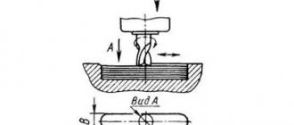
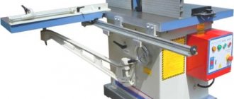
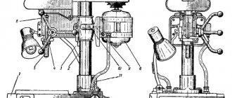
General view of the milling machine 676P
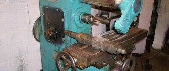
Photo of universal milling machine 676P
Photo of universal milling machine 676P
Photo of universal milling machine 676P
Photo of universal milling machine 676P
Photo of universal milling machine 676P
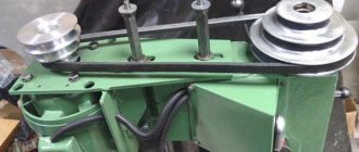
Gearbox
Gearbox of machine 676P
When considering the features of a milling machine, attention should be paid to the spindle speed box:
- The design is presented with gears that are made of high-strength steel. The passport of the 676p milling machine determines the possibility of carrying out repair and maintenance work by opening the housing and dismantling the gearbox. The housing is attached to the side.
- At the moment of switching, there is a possibility that the teeth will coincide and the gears will engage when the discs cannot be brought together. The passport contains information on application recommendations, where it is prohibited to change gears while the 676p milling machine is operating under load. This action can cause gear failure.
The description of this 676p milling machine also specifies that the speeds are controlled by switching the position of the corresponding handle.
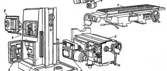
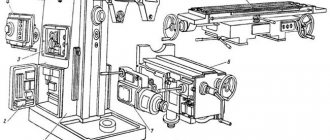
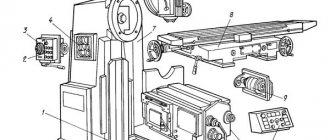
Location of components of the 676P cantilever milling machine
Location of components of the milling machine 676P
List of components of the wide-universal milling machine 676P
- 2. Gearbox - 75.1.001B
- 3. Spindle head - 6P.6.001
- 4. Feed box - 75.2.001B
- 6. Caliper - 6P.3.001
- 7. Bed - 6P.7.001
- 8. Electrical equipment - 676P.90.001
List of removable parts and accessories of the 676P milling machine
- 1. Vertical head - 5P.4.001
- 5. Corner horizontal table - 6P.81.001
- Universal table - 6P.82.001
- Vise GOST 14904-69
- Round table - 5P.84.001
- Dividing head - 5P.85.001
- Guitar – 6P.86.001
- Slotting head - 5P.87.001
- Tool cabinet - 5P.55.001B
- High-speed head - 75.88.001B
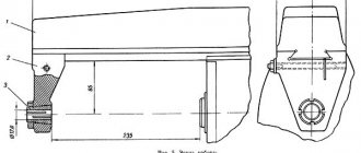
Headstock
Spindle head 676P
This structural element is also represented by a separate housing in which the gears are located. The structure can move along installed guides, which represents a transverse feed. The decoding of the name of the machine determines that it belongs to the vertical milling group due to the vertical position of the spindle itself. The tool is clamped using a special cleaning rod. Intermediate stops are installed as a limiter. The design features allow for coordinate boring work. For this purpose, an indicator holder and a tile holder were installed, which are necessary for fixing the measuring tile.
Location of controls for the 676P cantilever milling machine
Location of controls for milling machine 676P
List of controls for the 676P cantilever milling machine
- 1. Spindle reverse
- 2. Handle for turning on the mechanical table feed
- 3. Table clamp handle in vertical direction
- 4. Table clamp handle in horizontal direction
- 6. Gear shift knob
- 7. Speed dial fungus
- 8. Starting and stopping the main engine
- 9. Headstock clamp handle
- 10. Handle for setting the spindle to a vertical position
- 11. Vertical spindle sleeve clamp
- 12. Handle for moving the vertical spindle sleeve
- 13. Tool clamping in a vertical spindle
- 14. Vertical head clamp nut
- 15. Mechanical feed handle for spindle headstock
- 19. Light switch
- 20. Clamping the spindle head trunk
- 21. Flywheel for manual movement of the spindle head
- 22. Tool clamping in a horizontal spindle
- 23. Flywheel for manual spindle rotation
- 25. Rapid movement handle
- 27. Feed switch handle
- 29. Flywheel for manually moving the table in the longitudinal direction
- 31. Serve set mushroom
- 32. Flywheel for manual movement of the table in the vertical direction
- 33. Cooling switch
- 34. Connecting the machine to the network
- 35. Signs
Manual
Download the passport (operating manual) of the 676P machine
Today, it is quite difficult to find spare parts for the 676p milling machine, since its technical characteristics are somewhat inferior to those of modern models of milling machines. However, more recently, the equipment in question was installed in many workshops where small-scale and single-piece production was carried out. The instruction manual provides for the installation of additional equipment, for example, for performing slotting operations. This determines the versatility of the equipment. Other features of the model include the ability to rotate the spindle head by a certain degree within a set limit. The operating instructions provide for the use of several manual flywheels to move the table to the cutting tools and rotate the spindle head.
Main design elements
Kinematic diagram of the machine 676P
The design of the 676p universal milling machine is represented by the following main elements:
- Mains and electric pump switch. The electrical circuit provides for complete de-energization if necessary. In this case, the electrical circuit is made in a classic style, when all power is controlled through the “start” and “stop” buttons.
- Control is represented by flywheels, which are used to control the table, spindle and headstock.
- The passport determines the presence of a fairly large number of handles, which are responsible for controlling the main elements during the processing of parts.
- The main part of the structure is represented by a vertical frame, on the sides of which controls are located. At the top there is a headstock with a gearbox and spindle feed; at the front there is a table with several controls and a feed mechanism. The structure has a base, which, if necessary, can be rigidly fixed with bolts.
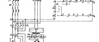
Electrical circuit of machine 676P
In general, we can say that the design of this model does not differ significantly from the design of many other models of the vertical milling group. The key feature of the 676p is the ability to rotate the spindle.
Kinematic diagram of milling machine 676P
Kinematic diagram of milling machine 676P
Main movement chain
From electric motor 1 with a power of 2.2 kW, the movement is transmitted to shaft 1 using V-belt transmission 2-3. From shaft 1 through the gearbox, rotation is transmitted to the drum gear 20, then to the shaft of the horizontal spindle VI.
The vertical spindle shaft VIII receives rotation from shaft VI through conical 22-23 and cylindrical 24-25 pairs.
Different positions of the gearbox gear blocks (7-6, 5-4, 14-15, 19-18) allow sixteen different speeds to be transmitted to the horizontal and vertical spindles.
Feed chain
All feeds of the machine (table in the vertical and longitudinal directions, spindle headstock in the transverse direction) are carried out mechanically and manually. In addition, fast travel is provided for all directions.
There is no independent feed drive in the machine. The feed mechanisms receive rotation from the main drive (shaft 1 of the gearbox) through the feed box. From the last shaft of the feedbox XIII, with the help of chain gears 50-62, 51-53, rotation is transmitted to the feed mechanisms of the table and spindle head.
Vertical feeds of the table are carried out as follows: shaft XVIII receives rotation from shaft XVII through a conical pair 63-64. To the vertical displacement screw XXIII, forward rotation is transmitted through gears 65-77, and reverse rotation through gears 74-75-76. Since the screw is fixed in the support, the table receives upward or downward movement.
Manual vertical movement is carried out by a flywheel sitting on shaft XXV, through conical pairs 80-81 and 78-79. Longitudinal feeds to the left and right are carried out by switching the clutch on shaft XIX, while rotation is transmitted through gears 66-65 and 74-75-67 to shaft XIX, through a bevel pair 68-69 to shaft XX, and then through gears 70-71 to the shaft screw XXI.
When the clutch on shaft XIV is switched, the headstock cross-feed mechanism imparts forward or reverse rotation to the nut 59 associated with the cross-feed screw, and the spindle head moves forward or backward.
The spindle head is manually moved by a flywheel using a conical pair 55-56 or 56-57.
Accelerated movements are carried out by coupling the coupling on shaft XVII with the coupling of the cylindrical wheel 49. Tables of the main movement and feed mechanisms are given in table. 5 and 6.
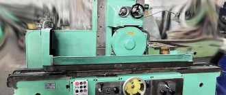
Design and description of machine components
Appearance
All milling machines of this class are designed for processing metal products on internal, external or shaped surfaces. With their help, you can form grooves of various configurations, splines on shafts, and make teeth for gears. Thanks to its universal design, characteristics and versatility, the machine successfully copes with the functions assigned to it.
The machine is characterized by a thoughtful arrangement of elements. A frame is installed on a cast iron base, on which the spindles, power unit, gearbox and work table are mounted. The latter has mounting grooves for fixing parts. There is a recess at the bottom of the equipment to collect chips. Additionally, there are coolant and coolant supply systems.
Design features and characteristics of the widely-universal machines of the 676P series:
- the presence of two spindle heads for installing cutters. One of them has a horizontal arrangement, and the second is rotary-vertical. This makes it possible to process parts of complex configurations;
- variety of operating modes. First of all, this relates to the number of spindle revolutions and feeds. For processing a specific workpiece, you can select the optimal mode;
- presence of a flywheel with vertical movement. It has a positive effect on the ergonomics of the equipment and also increases its technological capabilities.
Additionally, it is possible to install components that are not included in the standard package. Thus, the list of operations performed increases and the processing time of one workpiece decreases.
The most common addition to the SF-676 universal milling machine is the slotting head. Since the equipment is quite stable and there are practically no vibrations on its body, it is possible to chisel parts made of hard steel.
Features of disassembling and assembling the 676P machine during repair
Periodically, in accordance with the schedule of scheduled maintenance, the machine must be disassembled for current, medium and major repairs in the following order:
- disconnect the machine from the power supply;
- remove accessories (vertical head, table, etc.)
- remove the spindle head trunk;
- remove the spindle head from its guides, for which:
- remove stops 14 (Fig.

- remove the bolts and tapered pins securing the bracket 13 screws 12
- release the wedge in the bed and move the headstock out of the guides forward;
- remove the flywheel 7 (Fig. 9), and then the rear casing 6, driving V-belts and chains, freeing the tension sprockets 12 for this;
- dismantle the gearbox drive shaft, thereby creating the opportunity to freely remove the gearbox, and then the shaft connected to the feedbox;
- remove the gearbox from the frame, having previously removed the screws and pins securing the gearbox flange;
- remove the cover on the frame from the side opposite to the side of the feed box mounting, separate the pump from the box body, and then, having released the mounting screws and pins, remove the feed box;
- disassemble the main desktop (Fig. 7), for which:
- release the screw attachments
- unscrew the screw from the running nut
- release wedge 5
- remove the worktable from the horizontal guides of the support
Further disassembly of the units should be carried out according to the drawings of general types of units given in the manual.
Disassembled parts should be thoroughly washed with kerosene or white spirit and wiped dry. It is necessary to make marks on non-rotating bushings to determine their position before disassembly. This will ensure their alignment.
Reassembly after repair must be done in the reverse order of disassembly.
When assembling, pay attention to the adjustment of the rolling bearings (avoid excessive tension, which can cause overheating of the bearings). When making major repairs, grinding or scraping guides, you must remember that the correct position of the lead screws is determined by compensators, the thickness of which is set during the assembly process.
Design Features
The machine is recognized as widely versatile due to the presence of two spindles - horizontal and vertical, as well as a large number of different accessories for the machine. The base of the machine is made of cast iron and ensures the stability of the equipment while absorbing vibrations. The design features allow you to work with both small workpieces and parts up to 80 cm in length. At the same time, the machine is small in size and can be installed in a small workshop.
Spindle speed box
The gear transfer mechanism is located in front of the base of the box. When the handle is positioned as vertically as possible, discs with holes are separated. If the discs need to be brought back to the opposite position, the handle is lowered down.
Gearbox
To maintain the trajectory of the gears, the main gear is used, which is engaged when the gearbox reverse is engaged. In this case, the oil is served in very small portions.
Caliper
The caliper body is a dovetail mechanism. It is responsible for the movement of the main working area in two directions. Vertical advancement is carried out thanks to the guides that are available on the frame. Longitudinal movement is carried out due to horizontal guides. Control occurs due to the running shaft, and the latter receives movement from the gearbox.
Headstock
The spindle head mechanism is equipped with a cleaning rod. Thanks to it, the entire toolkit of the machine is clamped. To set the amount of automatic movement of the spindle head, there are intermediate supports.
Vertical head
The vertical head is mounted into the proboscis faceplate. The design has the ability to rotate 90° from the vertical axis. The operator can set the rotation angle to zero if necessary. In this case, the head must be secured with two pins using internal hexagon bolts. The splines transmit the rotational motion of the spindle tail, and double-row and roller bearings support the vertical spindle.
Corner horizontal table
This structure is cast from cast iron and bolted to the main work surface. For attachment there are T-shaped grooves - 3 pieces.
Vise
They can rotate around their own axis. They are an integral design of the machine and can be additionally mounted on both tables, which greatly facilitates the work.
Slotting head
The slotting head is built into a special round housing. This also includes a special trunk, which is built into the slotting and vertical heads.
Electrical diagram of milling machine 676P
Electrical diagram of milling machine 676P
List of elements of the electrical circuit of the 676P milling machine 676P
Gearbox
Feed box of machine 676P
For faster movement, a feed box was installed. A recommendation for using this function is to set the cross handle to the neutral position. This eliminates the possibility of a fairly large number of problems with gears.
The piston pump significantly extends the service life of the structure. Its intended purpose is to supply a lubricating fluid, which helps reduce friction. The design of the piston performs a reciprocating movement, due to which the lubricating fluid is sucked in and supplied to the friction area. To control the degree of lubrication, the 676p milling machine has a transparent eye, through which the process of oil mist formation in the gear friction zone is monitored.
Technical characteristics of the milling machine 676P
| Parameter name | 676P | 67K25PR |
| Main settings | ||
| Accuracy class according to GOST 8-82 | P | P |
| Dimensions of horizontal (corner) table, mm | 250 x 800 | 320 x 800 |
| Vertical table dimensions, mm | 250 x 630 | 250 x 630 |
| Maximum weight of the workpiece, kg | 100 | 350 |
| Distance from the axis of the horizontal spindle to the working surface of the horizontal table, mm | 80..460 | 45..595 |
| Distance from the end of the vertical spindle to the working surface of the horizontal table, mm | 0..380 | 10..490 |
| Overhang of the vertical spindle axis, mm | 125..375 | 165..485 |
| Maximum longitudinal stroke of the table (X), mm | 400 | 400 |
| Maximum stroke of the spindle head of the vertical spindle (Y), mm | 250 | 320 |
| Maximum vertical travel of the table (Z), mm | 380 | 450 |
| Vertical and horizontal spindles | ||
| Horizontal spindle rotation speed, rpm | 50..1630 | 40..2000 |
| Vertical spindle rotation speed, rpm | 63..2040 | 40..2000 |
| Number of spindle speeds | 16 | 18 |
| Limb division price, mm | 0,05 | 0,02 |
| Rule division price, mm | 1,0 | |
| Taper of horizontal and vertical spindles | Morse 4 | |
| Spindle head feed limits, mm/min | 13..395 | 10..1000 |
| Number of spindle head feeds | 16 | b/s |
| Accelerated speed of the spindle head, m/min | 0,9 | |
| Maximum headstock feed force, N | 9500 | |
| Maximum permissible torque on the horizontal/vertical spindle, Nm | 230/ 82 | |
| Tool clamp-release | Manual | Mechanism |
| Spindle braking | No | |
| Vertical milling head | ||
| Maximum axial movement of the vertical spindle, mm | 60 | 60 |
| Maximum angle of rotation of the vertical head in the vertical plane, degree | ±90 | ±90 |
| Weight of vertical milling head, kg | 70 | |
| Corner horizontal table | ||
| Number of table feeds in longitudinal and vertical direction | 16 | b/s |
| Limits of longitudinal and vertical table feeds (X. Y), mm/min | 13..395 | 10..1000 |
| Accelerated table travel in longitudinal and vertical directions, mm/min | 935 | 1800 |
| Maximum table feed force, N | 9500 | |
| Number of T-shaped slots | 5 | 5 |
| Weight of corner horizontal table | 105 | |
| Corner universal table | ||
| Dimensions of horizontal universal table, mm | 200 x 630 | 200 x 630 |
| Maximum rotation angle in the horizontal plane, degrees | ±20 | ±20 |
| Long side slope, degrees | ±45 | ±45 |
| Slope of the short side, degrees | ±30 | ±30 |
| Weight of corner horizontal table | 55 | |
| Round horizontal-vertical table | ||
| Table faceplate diameter, mm | 250 | 250 |
| Overall dimensions, mm | 345 x 330 x 110 | 338 x 485 x 140 |
| Round table weight | 60 | |
| Drive and electrical equipment of the machine | ||
| Number of electric motors on the machine | 2 | 4 |
| Main drive electric motor, kW | 2,2 | 3 |
| Feed drive electric motor, kW | — | 1,3 |
| Electric motor for lubrication and tool clamping, kW | — | 0,55 |
| Cooling pump drive electric motor, kW | 0,12 | 0,12 |
| Total power of electric motors, kW | 2,32 | 4,97 |
| Dimensions and weight of the machine | ||
| Machine dimensions (length x width x height), mm | 1282 x 1215 x 1780 | 1685 x 1655 x 1865 |
| Machine weight, kg | 910 | 1350 |
- Tool wide-universal high-precision milling machine model 676p. Manual 676P.00.000. Vilnius, 1975
- Avrutin S.V. Fundamentals of Milling, 1962
- Avrutin S.V. Milling, 1963
- Acherkan N.S. Metal-cutting machines, Volume 1, 1965
- Barbashov F.A. Milling business 1973, p.141
- Barbashov F.A. Milling work (Vocational education), 1986
- Blumberg V.A. Milling machine handbook, 1984
- Grigoriev S.P. Practice of coordinate boring and milling work, 1980
- Kopylov R.B. Working on milling machines, 1971
- Kosovsky V.L. Handbook of a young milling operator, 1992, p. 180
- Kuvshinsky V.V. Milling, 1977
- Nichkov A.G. Milling machines (Machinist's Library), 1977
- Pikus M.Yu. A mechanic's guide to repairing metal-cutting machines, 1987
- Plotitsyn V.G. Calculations of settings and adjustments of milling machines, 1969
- Plotitsyn V.G. Setting up milling machines, 1975
- Ryabov S.A. Modern milling machines and their equipment, 2006
- Skhirtladze A.G., Novikov V.Yu. Technological equipment for machine-building industries, 1980
- Tepinkichiev V.K. Metal cutting machines, 1973
- Chernov N.N. Metal cutting machines, 1988
- Frenkel S.Sh. Handbook of a young milling operator (3rd ed.) (Vocational education), 1978
Bibliography:
Related Links. Additional Information
- Milling machines: general information, classification, designation
- Comparative characteristics of cantilever milling machines of the 6N, 6M, 6R, 6T
- Feed box for console milling machines of the 6M : 6M12P, 6M13P, 6M82, 6M83, 6M82Sh, 6M83Sh
- Feed box for console-milling machines of the 6P : 6Р12, 6Р13, 6Р82, 6Р83, 6Р82Ш, 6Р83Ш Feed box for console-milling machines of the 6Т : 6T12, 6T13, 6T82, 6T83, 6Т82Ш, 6Т83Ш
Home About the company News Articles Price list Contacts Reference information Interesting video KPO woodworking machines Manufacturers