Information about the manufacturer of the screw-cutting lathe 1M65
The manufacturer of the 1M65 universal screw-cutting lathe is the Ryazan Machine Tool Plant RSZ , founded in 1949.
The Ryazan Machine Tool Plant produced its first machine on February 21, 1949 - it was a 164 series screw-cutting lathe. Within a short time, the plant put into production three more series of lathes - 166, 165 in 1953, 163 in 1956.
As the design of the machines improved, the plant produced more and more modern models - 1M63, 1M63B, 1M63BF101, 1M63N, 16K30, 1A64, 16K40, 1M65, 1N65.
Based on universal lathes, the Ryazan Machine Tool Plant mastered the production of CNC lathes - 16K30F3, 16M30F3, 16K40RF3, 16R50F3, etc.
The plant has also mastered the production of modern turning machining centers with a number of coordinates from 4 to 8, CNC lathes of inclined 1P756DF3 and horizontal layouts, pipe processing machines 1A983, 1N983 - for processing the ends of pipes with a diameter of up to 460 mm, wheel lathes, roll lathes, machines for processing deep holes and etc.
Machine tools produced by the Ryazan Machine Tool Plant RSZ
- 1A64
universal screw-cutting lathe Ø 800 - 1A983
pipe cutting machine Ø 800 - 1M63
universal screw-cutting lathe Ø 630 - 1M63B, 1M63BG
high-power screw-cutting lathe Ø 630 - 1М63БФ101
screw-cutting lathe with digital display Ø 630 - 1М63МФ101
screw-cutting lathe with digital display Ø 630 - 1М63Ф101
screw-cutting lathe with digital display Ø 630 - 1M63N
universal screw-cutting lathe Ø 630 - 1M65
universal screw-cutting lathe Ø 1000 - 1Н65
universal screw-cutting lathe Ø 1000 - 1N983
pipe cutting machine Ø 830 - 1P756DF3
CNC lathe Ø 630 - 16K30F3
CNC lathe Ø 630 - 16K30
universal screw-cutting lathe Ø 630 - 16K40
universal screw-cutting lathe Ø 800 - 16M30F3
CNC lathe Ø 630 - 16Р25П
high-precision screw-cutting lathe Ø 500 - 163
universal screw-cutting lathe Ø 630 - 165
universal screw-cutting lathe Ø 1000 - DIP-300
universal screw-cutting lathe Ø 630 - DIP-400
universal screw-cutting lathe Ø 800 - DIP-500
universal screw-cutting lathe Ø 1000 - TNP-111
table lathe Ø 150
Design features of the 1m65 machine
the rigidity, vibration resistance and temperature stability of the design allow obtaining the necessary processing accuracy; two prismatic guide frames, combined with the high reliability of other components, ensure a long service life of the machine while maintaining the original accuracy; the reverse spindle rotation frequency is 1.3 times higher than the direct one, which reduces processing time thread turning of long cones is carried out by simultaneous longitudinal feed of the support and feed of the cutting slide with their corresponding rotation, the feed box has a high rigidity of the kinematic chain, has two electromagnetic clutches for remote gear shifting without stopping the machine, all power gears of the kinematic chain are made of alloy steel, hardened and ground guards for the cutting area and chuck, electrical and mechanical locking guarantee safe operation of the machine; high drive power and rigidity of the machine; a wide range of spindle speeds and feeds allow full use of the capabilities of advanced tools when processing various materials
Overhaul of the screw-cutting lathe 1M65 RMTs 3000, (Ryazan) is carried out at our production base
The warranty on machines after major repairs is 12 months
- We will carry out a major overhaul of your screw-cutting lathe.
1M65 universal screw-cutting lathe. Purpose, scope
The universal screw-cutting lathe model 1M65 replaced the outdated model of the machine of the same series 165.
1M65 screw-cutting lathe is designed for processing parts of medium and large sizes, in conditions of single and small-scale production. The machine can perform external and internal turning, including turning cones, boring, drilling and cutting threads - metric, modular, inch and pitch).
1M65 lathe is designed for processing ferrous and non-ferrous metals at high cutting speeds with cutters made of high-speed steel and hard alloys.
Operating principle and design features of the 1M65 machine
The technical characteristics and rigidity of the design of the machine bed, carriage, and spindle allow full use of the capabilities of working at high cutting speeds using cutters made of high-speed steel or equipped with carbide plates when processing parts made of ferrous and non-ferrous metals.
1M65 machine has a mechanical movement of the upper part, which allows turning long cones. Turning of short tapers is also carried out by moving the upper part of the support.
Changing the feed rates and adjusting the pitch of the thread being cut is carried out by switching the gears of the feed box and adjusting the set of interchangeable gears.
The support has rapid movement in the longitudinal and transverse directions, which is carried out by an individual electric motor.
The closed feed box provides cutting of standard threads. Precise threads are cut using replaceable gears, bypassing the feed box.
The technical characteristics and rigidity of the machines allow full use of the capabilities of high-speed and carbide tools when processing both ferrous and non-ferrous metals.
Type of climatic modification - UHL4 according to GOST 15150-69.
Accuracy class - N according to GOST 8-82E. Roughness of the machined surface V 6.
History of the 165 series screw-cutting lathe
In 1934
, the Moscow Machine Tool Plant mastered the production of heavy universal screw-cutting lathes DIP-300, DIP-400, DIP-500. A screw-cutting lathe from the German company VDF was chosen as a prototype.
IN 1944
In 2009, the production of these machines was transferred to
the Ryazan Machine Tool Plant RSZ .
In 1953
In 2008, the first machine of the 165 series, model 165, was put into production (processing diameter - Ø 1000 mm).
Serial production of lathes: 1m65, 1n65.
Purpose and description of lathe 1m65
The 1m65 screw-cutting lathe is capable of fully satisfying the technological requirements for the corresponding production process. It has become a full-fledged replacement for the DIP 500 lathe, which was produced almost 60 years ago. The 1m65 unit differs from its predecessor in the larger permissible workpiece length and spindle rotation speed, electric motor power (main drive) and many other parameters.
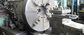
The unit is often used in a frontal version, i.e. for processing medium and large parts mounted on a plan washer. This kind of lathe is most often used for working on metal, including a wide variety of steels and its alloys, non-ferrous metals and polymer materials. By using cutters made of high-speed steels or equipped with carbide inserts, parts can be processed at high cutting speeds.
1m65 lathes were produced at the Ryazan Machine Tool Plant. Now spare parts and components for them are also on sale, the price is acceptable.
The design of the 1m65 screw-cutting lathe is practically no different from other representatives of the turning fleet. The design and sufficient rigidity of the bed, its spindle, carriage and other power elements make the technical capabilities of this unit a reality. Due to sufficient movement of the upper part of the caliper, high-quality turning of tapered surfaces of different lengths is possible. Preparing the machine for thread cutting involves adjusting its pitch using the gear wheels of the feed box or a set of replaceable gears.
The feed box has a closed type design, which allows for threads of normal accuracy. For a similar operation, but with high precision, the feed is done using a set of replaceable gears (without a box). For efficiency, the machine support is equipped with a separate electric drive that performs accelerated cutter transitions (transitions) in 2 directions. Switching the spindle speed and the amount of movement of the cutter are the handles on the gearbox and feeds, respectively. Two flywheels are responsible for the movement of the tailstock along the bed and the extension of its quill.
The layout of the main elements of the 1m65 lathe will help in its study and mastering by specialist turners, personnel of the main and auxiliary departments of the enterprise.
The manual (manual) for the maintenance and operation of the 1m65 lathe, among other information, provides consumers with a list of possible turning operations:
- Trimming and cutting.
- Three types of thread cutting (inch, modular and metric).
- External turning and internal boring (including conical surfaces)
A degree of surface roughness of parts corresponding to class V6 is achieved. For all cutting operations, it is allowed to use tools made in accordance with current standards. A certificate of conformity is required.
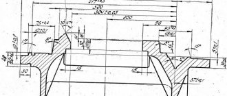
Landing and connecting dimensions of screw-cutting lathe 1M65
Spindle of screw-cutting lathe 1m65
Drawing of a spindle of a screw-cutting lathe 1m65
Our services for enterprises operating 1M65 machines
PKF RemStan LLC specializes in working with turning equipment. Our company offers the following types of services for enterprises using a 1M65 screw-cutting lathe :
- all types of repairs - from minor routine to major;
- full technical service;
- modernization by installing CNC.
All work is performed by professionals. PKF RemStan LLC necessarily provides a guarantee for services - the period is 12 months. Contact us - we will help you maintain and improve the characteristics of your equipment, making its operation economically profitable for your enterprise.
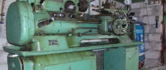
The 1M65 screw-cutting lathe is an outdated model of the 1N65 machine, one of the most common machines in the former USSR, which allows turning of medium- and large-sized parts. The machine was exported to many countries around the world. Screw-cutting lathes model 1M65 have proven themselves to be reliable and unpretentious, not requiring special attention.
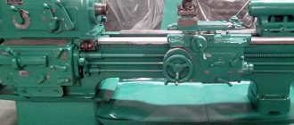
Location of the components of the 1M65 lathe
Location of the main components of a 1m65 lathe
Components of the 1M65 lathe
- bed
- headstock
- tailstock
- caliper
- carriage
- apron
- gearbox
- gear wheels (replaceable)
- cartridge
- lunette movable
- cooling
- fencing
- chuck guard
- fixed steady rest
- electrical cabinet
- electrical pipe installation
- electromagnetic coupling
- fencing
- fencing
- DRO stand
Structural design of a 1m65 lathe
A rigid frame of one-piece design is the basis for the assembly of all elements, parts and assemblies of the machine. On top of it there are 3 prismatic guides. The middle one is used to move the tailstock, and the two outer ones are used for the carriage. In the inner part of the frame there are hatches sloping towards the tailstock. Along them, chips are removed into the bed trough and waste coolant is collected. On the left side of the frame cavity is the location of the electric motor (main drive) and the coolant pump with a container for it.
At the front, on the right side of the frame, there is a bracket with bushings for the lead screw and shaft. To avoid their deflection, intermediate supports are installed when the RMC is 5000 mm or more. The headstock sits on top of the bed on the left and is secured with bolt and pin connections. Its housing contains a spindle assembly with an electromagnetic brake and mechanisms:
- Reverse (for carriage or when cutting threads).
- Switching speeds.
- 8-fold increase in thread pitch.
The lubrication system is also located here. An electrical switch cabinet is installed next to the headstock. The spindle rotates in three bearing units, two of which are adjustable. The tailstock is moved manually by rotating the flywheel of its gear drive. A center rotating on supports is installed in the quill assembly of this headstock. It has grooves for the shanks of cutting tools (drills, reamer, etc.). The machine support is cross-shaped. Moreover, it moves along the workpiece along the guides of the frame together with the carriage, and across it along the grooves of the latter.
A tool slide with a 4-seater tool holder is installed on top of the support, which can be rotated to any angular position relative to the axis. 1M65 lathes of a number of modifications have digital indication devices (DDI) for linear movements. Its converter transmits movement to the lead screw through a bellows. Readings are made according to the divisions of the dial or on the DRO screen.
The caliper moves using an apron, which, in turn, moves due to a rotating lead screw or shaft. The caliper has 4 electromagnetic clutches built into it, so it is controlled by one handle. In this case, the tilt of the switched on handle coincides with the feed direction. The overrunning clutch will ensure accelerated movement of the caliper even when the working feed is turned on.
The feed box is designed in such a way that the first half of their range and the processes of cutting all types of threads are implemented without replaceable gears. They are needed only to provide another part of the innings. The machine is supplied with a 4-jaw chuck without self-centering. For turning parts of considerable length and insufficient rigidity, there are 2 supports-rests (fixed and movable). The movable steady rest is mounted on the machine carriage. It will support parts with a diameter of 70 – 250 mm in close proximity to the cutter. Direct - installed directly on the frame guides and fixed with a bolt clamp in an arbitrary location. This steady rest holds a workpiece with a diameter of 70 – 380 mm.
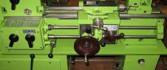
Location of controls for screw-cutting lathe 1M65
Location of controls for a 1m65 screw-cutting lathe
Specification and purpose of machine controls 1M65
- Setting the spindle to the required number of revolutions
- Setting the spindle to the required number of revolutions
- Setting the spindle to the required number of revolutions
- Setting the spindle to the required number of revolutions
- Adjustable to normal or increased pitch
- Setting for right-hand or left-hand thread cutting
- Starting direct spindle rotation
- Adjustment for feeds and cutting of metric, modular and inch threads
- Adjustment for feed rate and thread pitch
- Setting the feed rate and thread pitch, turning on the lead screw directly
- Adjustment for feed rate and thread pitch
- Turning the feed on and off (turning the ring gear on and off)
- Setting for feed or thread cutting (activation of lead pin or lead roller)
- Manual longitudinal movement of the carriage
- Start spindle reverse rotation
- Setting for thread or feed (turning on the uterine nut, blocking the inclusion of mechanical feed)
- Manual movement of the cross slide
- Manual movement of the cutting sled
- Rotating and securing the cutting head
- Turning on longitudinal and transverse mechanical feeds and their reverse
- Enabling accelerated movements (longitudinal and transverse)
- Manual movement of the tailstock
- Quill attachment
- Slow manual movement of the quill
- Enabling slow or fast manual quill movements
- Fast manual movement of the quill
- Fixing the rotating center
- Turning off the tailstock stop
- Transverse movement of the tailstock
- Turning on the power supply
- Local lighting switch
- Jog start of direct spindle rotation
- Main drive stop
- Start cooling
- Stop cooling
- Starting direct spindle rotation
- Main drive stop
- Start spindle reverse rotation
SPECIAL MECHANISMS
Price: Check
Screw-cutting lathe mod. 1M65 (165) with RMC-5000 mm. (manufactured by the Ryazan Machine Tool Plant) is designed for processing a variety of parts and workpieces (rotation bodies) from different materials up to 5000 mm. length and up to 1000 mm. diameter, in conditions of single and small-scale production. The machine can perform external and internal turning, including turning cones, boring, drilling, reaming, cutting external and internal threads, etc. Cutting by type of threads: metric, modular, inch, pitch.
The technical characteristics and rigidity of the design of the machine bed, carriage, and spindle allow full use of the capabilities of working at high cutting speeds using cutters made of high-speed steel or equipped with hard alloy plates when processing parts made of ferrous and non-ferrous metals, and allow obtaining the necessary processing accuracy. 2-prism guides of the frame, in combination with the high reliability of other components, ensure a long service life of the machine while maintaining the original accuracy. The machine support has a mechanical movement of the upper part, which allows turning cones. Changing the feed rates and adjusting the pitch of the thread being cut is carried out by switching the gears of the feed box and adjusting the set of interchangeable gears. The support has the ability to accelerate movements in the longitudinal and transverse directions, which is carried out by an individual electric motor. The closed-type feed box has a high rigidity of the kinematic chain and ensures threading and switching of various feed rates. Changing the spindle speed and caliper feed speed is carried out by switching the gears of the gearbox and feedbox using handles. The tailstock is moved and the quill is extended manually. For processing workpieces and long parts, fixed and movable steady rests can be supplied in the kit.
| Specifications | 1M65-5000 |
| The largest outer diameter of the workpiece, mm: | |
| above the bed, mm | 1000 |
| above the caliper, mm | 600 |
| Largest workpiece, mm | 5000 |
| Diameter of a cylindrical hole in the spindle (not less), mm | 85 |
| Spindle end according to GOST 12595-72 | 1-15M |
| Height of the cutter installed in the tool holder, mm | 50 |
| Number of spindle speeds | 24 |
| Spindle speed, rpm | 5-500 |
| Number of innings | 32 |
| Feed, mm/rev: | |
| longitudinal | 0,20…3,05 |
| transverse | 0,07…1,04 |
| Maximum cutting force allowed by the feed mechanism, kgf: | |
| longitudinal | 1200 |
| transverse | 780 |
| Thread pitch | |
| metric, mm | 1…120 |
| modular, module | 0,5…30 |
| inch, threads per inch | 28…1/4 |
| Maximum mass of the processed product, kg | 5000 |
| Dimensions, mm: | |
| length | 8180 |
| width | 2100 |
| height | 1876 |
| Machine weight, kg | 15750 |
Write to us
Return to home page
Description of the design of the main components of the 1M65 screw-cutting lathe
bed
The bed is the basic assembly unit on which all other assembly units and mechanisms of the machine are mounted.
On the top of the frame there are three prismatic guides, of which the front and rear are the base of the carriage, and the middle one is the base of the tailstock.
Inside the frame there are inclined hatches for removing chips and coolant in the direction opposite to the workplace.
Under the left head part of the frame there are niches, in one of which the main drive electric motor is mounted, and in the other - an electric cooling pump with a coolant reservoir. The trough for collecting coolant is made monolithic with the frame body.
On the right side of the frame, on the front wall, a bracket is mounted with supports for the lead screw and lead shaft built into it.
To prevent sagging of the lead screw and the lead shaft, the machine with RMC = 5000 mm has two suspensions.
Headstock
Spindle head of screw-cutting lathe 1m65
Spindle head of screw-cutting lathe 1m65
The front headstock is installed on the left head part of the frame, fixed with pins and secured with bolts.
The following are mounted in the spindle head housing:
- electromagnetic clutch for spindle braking
- spindle unit
- step increase link 8 times
- mechanism for changing the direction of movement of the carriage or threading
- spindle speed adjustment mechanism
- forks for moving gear blocks
- shift knobs and other parts
- Lubrication system
- electrical cabinet
The spindle is mounted on three rolling bearings, of which the front and rear are adjustable.
Tailstock
The rear headstock moves along the frame guides from the manual gearbox by rotating the roller.
A rotating spindle is built into the headstock quill, the front support bearings of which are adjusted using nuts.
The tailstock spindle has a slot for the legs of the tail cutting tool.
Caliper
The support of the cross design has longitudinal movement along with the carriage along the frame guides, and transverse movement along the carriage guides.
Both movements are carried out mechanically using a cross switch and manually by rotating the flywheel and carriage handle.
The cutting slide, carrying a four-position tool holder, moves manually and mechanically along the guides of the rotating part, which can be rotated around its axis at any angle.
The carriage of machines with a digital display device is equipped with a linear displacement transducer, which is connected to the transverse displacement screw using a bellows coupling.
The lateral movement can be counted using the dial and the DRO display.
Apron
The machine apron is of a closed type with a removable front cover. The movement of the caliper group is transmitted by the apron mechanism from the drive shaft or lead screw.
Due to the presence of four electromagnetic clutches in the apron, control of the mechanical movement of the caliper group is concentrated in one handle, and the direction of activation of the handle coincides with the direction of feed.
It is possible to enable rapid movement of the caliper in the direction of tilting the control handle.
Thanks to the overrunning clutch built into the apron, high speed can be activated when the feed is on. The rapid speed electric motor is installed on the apron.
A safety clutch mechanism is mounted in the apron, which prevents the machine from breaking due to overload.
Gearbox
Closed feed box with removable front cover.
The feed box mechanism allows you to get the first row of feeds and all the threads cut on the machine, without having to change the settings of the replacement gears.
To obtain the second row of feeds, replaceable wheels are installed: a = 42, b = c = 126.
Machine equipment
The machine includes a four-jaw non-self-centering chuck with a diameter of 1000 mm.
For processing non-rigid parts, the machine is equipped with two steady rests - movable and fixed.
The movable rest is mounted on the carriage and supports the part directly near the cutter. The breadcrumb coverage diameter is provided in the range from 70 to 250 mm.
The stationary steady rest is installed on the frame guides anywhere and secured with a bolt using a clamp.
It is equipped with crackers and rollers, which are installed depending on the processing conditions.
The diameter of coverage of the workpiece in the stationary steady rest is provided in the range from 70 to 380 mm.
Main components and principle of operation
bed , being the base of the machine, houses all the mechanisms and assemblies. On its surface there are prismatic guides for basing and moving the caliper and tailstock.
When the machine is designed with an interaxial distance of 5000 mm or more, supporting brackets are located on the frame to prevent sagging of the lead screw. Open inclined windows at the bottom of the structure serve to drain emulsion and metal shavings.
Some models have a recess in the frame; the letter “G” is indicated in the marking to indicate it.
The headstock is attached to the frame on the left side with clamping bolts and fixing pins. The closed housing contains a spindle assembly, a brake clutch, a gearbox, shift forks, and a unit for changing the size of the thread being cut. The spindle is mounted on precision rolling bearings, which are lubricated and adjusted during assembly at the factory and do not require subsequent adjustment.
A through hole in the headstock allows processing bar workpieces with a diameter of up to 120 mm.
Steady rests are used when processing flexible shafts to eliminate axial deflection. The workpiece in this device rests on crackers and rollers. There are two types of lunettes:
Movable - moves in the longitudinal direction along with the cutting carriage and is stationary. The diameter of the installed parts is from 70 mm to 250 mm.
Fixed - fixed in any position on the surface of the guides with clamping bolts. Workpiece range 70…380 mm.
The tailstock is attached to the right side of the frame in a rigid position with strips and bolts. In addition, it can be moved along the guides and fixed in any place for subsequent work. The unit body houses a movable quill, which has an accelerated movement during idle and a working movement during processing. An axial tool is installed into the conical hole of the quill to process the workpiece from the end.
The support is used to place the working tool and transmit movement to it in the longitudinal and transverse directions. A four-position tool holder with mechanical or manual movement, capable of rotating at any angle around its own axis, is installed on the top. The accelerated movement of the caliper is carried out by a separate electric motor.
The standard lathe chuck The workpiece is clamped manually using a specialized key. If necessary, use cartridges of other sizes, as well as various faceplates.
To fix the workpiece, cams are used; straight cams are clamped by the outer surface, and reverse cams are clamped by the inner diameter.
A protective casing installed in the processing area prevents chips and coolant from flying out.
Electrical equipment of the machine
All production processes of turning on, turning off and monitoring the operation of the machine are carried out by electrical equipment. It consists of motors, wiring, a push-button panel, and control equipment. The electrical cabinet is located in the rear niche of the spindle head, and the control panel is in the front part. For trouble-free operation and the elimination of short circuits, the circuit includes thermal relays with automatic switch-offs.
Main motor 22 kW, electric motor for fast feeds of the caliper 1.5 kW, mains voltage 380 V, current frequency 50 Hz.
Adjusting the screw-cutting lathe 1M65
During the operation of the machine, there is a need to regulate individual components of the machine in order to restore their normal operation.
Adjusting the spindle bearings of a 1M65 screw-cutting lathe
Adjusting the spindle bearings (Fig. 10.5)
Adjust the spindle front bearings in the following order:
1. Remove the cartridge;
2. Remove screws 1 and 2;
3. Unscrew screw 3 and remove cracker 4;
4. Loosen nut 5;
5. Using nut 6, pull off the inner ring of the bearing to make it easier to remove half rings 7;
6. Unscrew the nut 6 from the half rings 7 and remove them from the groove;
7. Loosen the thrust bearings by unscrewing nut 8, no more than 1/2 turn;
8. Adjust the radial bearing of the front support by moving its inner conical ring with nut 5 until the spindle flange is pressed in a vertical plane relative to the headstock housing by 5...10 µm from a load of 8 kN. The load is applied BOTTOM UP to the spindle flange through a dynamometer in the spin measurement plane. Using measuring tiles or lead spacers, measure the WIDTH of the groove under the half rings 7. Grind the half rings to the size of the groove and install them;
9. Using nut 5, tighten the inner ring of the bearing and clamp half-ring 7;
10. Screw nut 6 onto half-ring 7 to prevent them from falling out and secure it with screws 2 and 1;
11. Use nut 6 to adjust the axial clearance of the ball thrust bearings so that the axial runout of the spindle does not exceed 0.015 mm;
12. Insert cracker 4 into the groove of nut 8 and tighten screw 3.
Adjust the spindle rear support bearings in the following order:
1. Remove screw 10;
2. Using nut 9, adjust the bearing by moving its inner conical ring until the spindle is pressed in a vertical plane at the rear SUPPORT relative to the headstock housing by 40...50 µm from a load of 8 kN. The load is applied through a dynamometer to the spindle at this support from bottom to top in the spin measurement plane (remove flange 11);
When tightening the bearing with nut 9, loosen its inner ring. first unscrew screw 10 and repeat the adjustment;
3. Having adjusted the bearing, tighten screw 10.
After adjusting the bearings, the spindle, when its gears are turned off, must be freely turned by HAND, and the accuracy standards must comply with the accuracy tests of GOST 18097-88.
Spindle axis alignment (Fig. 10.6)
If the spindle axis is not parallel to the bed guides, loosen all the bolts securing the front headstock to the bed and use screws 1. screwed into the block 2. which is installed under the headstock. Align the spindle axis and tighten the fastening bolts.
Spindle bearings
The spindle of the 1M65 screw-cutting lathe is mounted on 5 bearings:
- 215. Front bearing No. 4-3182140K double-row radial roller bearing, TU37.006.107-80
- 214. Bearing No. 5-8144 single thrust ball, GOST 7872-89
- 206. Bearing No. 12736 single radial ball, GOST 8328-75
- 207. Rear bearing No. 4-3182132K double-row radial roller, TU37.006.107-80
Technical characteristics of bearing No. 3182140K
Bearing 3182140K is a double-row radial roller bearing, with short cylindrical rollers, with a flangeless outer ring (as a result of which the set of rolling elements on the cage is able to move and create a “floating” support), with a conical mounting hole (1:12), a groove and holes for adding lubricant.
The main place of operation of such bearings is machines for various applications, units where high radial loads and speeds are applied. This standard size, like most roller bearings in this series, is currently produced only with high precision. The separator is usually brass, which is usually not reflected in the number. Recently, this type has been made exclusively with a groove on the outer ring and holes for lubricant supply. This design feature is reflected in the number with the letter K (or K1). The production of this type was previously carried out at the Moscow Bearing Plant GPZ-1, and now at a branch of the Samara Aviation Bearing Plant in Volzhsky, which are part of the structure of the European Bearing Corporation, which sells its products through a network of dealers and its own Trading House. The approximate price of a new bearing is about 22,500 rubles, however, as a rule, there are no free finished products in the manufacturer’s warehouses, and out of stock, this type is sold of illiquid quality in companies of the corresponding profile. Therefore, if you want to buy a quality bearing of this type, you will most likely need to wait for it to be manufactured.
Imported bearings of this standard size have the designation NN3040K (the presence of the letter K in the number is mandatory, since it indicates a conical fit) and are most often sold, like domestic ones, produced long ago in the EEC countries, for example, ZKL bearings - Czech production (the plant operates now, but most often it is illiquid stock that is on sale), DKF - GDR. High-quality imported bearings (SKF and FAG) are most often supplied only to order, the estimated price is about 3,000 euros. The accuracy class is indicated as P4 or P5, the groove is W33.
Dimensions and characteristics of bearing 3182140K (NN3040K)
- Inner diameter (d): – 200 mm;
- Outer diameter (D): – 310 mm;
- Width (H): – 82 mm;
- Weight: – 21.9 kg;
- Roller dimensions: - 26x26 mm;
- Number of rollers: - 52 pcs;
- Dynamic load capacity: - 665 kN;
- Static load capacity: - 1140 kN;
- Maximum rated speed: - 2800 rpm.
Bearing diagram 3182140K (NN3040K) of a 1e61m lathe
Photo of bearing 3182140K (NN3040K)
Technical characteristics of bearing No. 8144
This is a thrust ball bearing designed for operation under axial load in units with low rotation speeds.
Their design is dismountable (two rings, one of which is 1-2 mm smaller than the other in inner diameter and a set of rolling elements on the cage), so installation of individual parts can occur independently of each other. In Russia it is produced at one plant: 1 gas processing plant (Moscow). Modification 8144 NL (with a brass separator), produced with zero accuracy class. When purchasing a bearing from an official representative, it costs just over 6,000 rubles.
The international designation of bearing 8144 is 51144. The brass cage is designated in the number by the letter M. The most widely used brands in Russia are FAG (Germany, expensive and high-quality) and ZKL (Czech Republic). The latest manufacturer's products are cheaper. The first product, with a brass separator, has a price of about 20,000 rubles.
Used in industrial equipment.
Dimensions and characteristics of bearing 8144 (51144)
- Inner diameter (d): – 220 mm;
- Outer diameter (D): – 270 mm;
- Width (H): – 37 mm;
- Weight: – 4.5 kg;
- Ball diameter: - 19.05 mm;
- Number of balls: - 35 pcs;
- Dynamic load capacity: - 178 kN;
- Static load capacity: - 735 kN;
- Maximum rated speed: - 1300 rpm.
Diagram of bearing 8144 (51144) of lathe 1e61pm
Photo of bearing 8144 (51144)
Specifications
| Model | 1Р65-1 / 1Р65-3 / 1Р65-5 / 1Р65-8 / 1Р65-10 |
| Main settings | |
| The largest diameter of processing the product above the bed | 1000 mm |
| The largest diameter of workpiece processing above the support | 650 mm |
| Distance between centers (RMC) | 1000 / 3000 / 5000 / 8000 / 10000 mm |
| Accuracy class according to GOST 8-82 | N (P) |
| Maximum product weight | 8000 (10000 for machines with RMC from 5000 mm) kg |
| Headstock | |
| Clockwise spindle speed limits | 5 - 500 rpm |
| Hole in spindle | 128 mm |
| Flanged spindle end | 2 - 15M |
| Main engine power | 22 kW |
| Maximum permissible spindle torque | 9500 Nm |
| Calipers | |
| Maximum movement of the cutting slide | 0.022 - 0.88 mm |
| Limits of working feeds (longitudinal) | 0.06 - 2.42 mm/min |
| Limits of working feeds (transverse) | 0.022 - 0.88 mm/min |
| Limits of pitches of machined threads (metric) | 1 - 96 mm |
| Limits of pitches of machined threads (inch) | 24 - 0.25 threads per inch |
| Limits of pitches of machined threads (modular) | 0.5 - 24 module |
| Limits of pitches of machined threads (pitch) | 96 - 1 pitch diametrical |
| Rapid movement (longitudinal) | 3000 mm/min |
| Rapid movement (transverse) | 1000 mm/min |
| Dimensions and weight | |
| Length | 4100 / 6140 / 8180 / 9190 / 11380 mm |
| Width | 2200 mm |
| Height | 1770 mm |
| Net weight | 9850 / 12800 / 15750 / 16140 / 20300 kg |
Technical characteristics of the lathe 1M65
| Parameter name | DIP-500 (1d65) | 165 | 1m65 | 1n65 |
| Main settings | ||||
| Accuracy class according to GOST 8-82 | N | N | N, P | N, P |
| The largest diameter of the workpiece being processed above the bed, mm | 1000 | 1000 | 1000 | 1000 |
| The largest diameter of the workpiece above the support, mm | 620 | 600 | 600 | 650 |
| Maximum workpiece length (RMC), mm | 5000 | 2800, 5000 | 3000, 5000, 8000 | 1000, 3000, 5000 |
| Height of installed cutter, mm | 45 x 45 | 50 | ||
| The largest mass of the workpiece in the centers, kg | 5000 | 5000 | 5000 | |
| Spindle | ||||
| Diameter of through hole in spindle, mm | 100 | 85 | 85 | 128 |
| The largest diameter of the clamped rod, mm | 80 | 80 | 120 | |
| Maximum torque on the spindle, kN/m | 9,5 | |||
| Number of speed steps for direct spindle rotation | 12 | 24 | 24 | 24 |
| Spindle direct rotation frequency, rpm | 4,25..192 | 5…500 | 5…500 | 5…500 |
| Size of the inner cone in the spindle | KM 6 | 100, 1:20 | 100, 1:20 | 100, 1:20 |
| Spindle end according to GOST 12595-72 | 1-15M | 1-15M | 2-15M | |
| Diameter of standard cartridge, mm | 1000 | |||
| Spindle braking | There is | There is | There is | There is |
| Submissions | ||||
| Maximum longitudinal movement of the caliper RMC=3000, mm | 2520 | 2710 | 700, 2700, 4500 | |
| Maximum lateral movement of the caliper, mm | 600 | 600 | 600 | |
| The cost of dividing the dial during longitudinal movement, mm | No | 0,1 | 0,1 | 0,1 |
| Dial division price for transverse movement, mm | 0,05 | 0,05 | 0,05 | 0,05 |
| Maximum longitudinal movement per dial revolution, mm | 10 | 50 | 50 | 50 |
| Maximum lateral movement per dial revolution, mm | 12 | 6 | 6 | 6 |
| Number of longitudinal feed stages | 32 | 32 | 40 | |
| Limits of longitudinal feeds, mm/rev | 0,225..3,15 | 0,20..3,05 | 0,20..3,05 | 0,05..3,05 |
| Transverse feed limits, mm/rev | 0,114..1,6 | 0,07..1,04 | 0,07..1,04 | 0,017..1,04 |
| Maximum longitudinal cutting force Pz, kN | 12 | 12 | 41 | |
| Maximum transverse cutting force Px, kN | 780 | 780 | ||
| Speed of fast movements of the caliper, longitudinal, m/min | No | 2,16 | 3 | 3 |
| Speed of fast movements of the caliper, transverse, m/min | No | 0,735 | 1 | 1 |
| Number of metric threads to be cut | 22 | 44 | ||
| Limits of pitches of cut metric threads, mm | 1..14 | 1…120 | 1…120 | 1…120 |
| Number of inch threads to be cut | 36 | 31 | ||
| Limits of pitches of cut inch threads | 2..28 | 28…¼ | 28…¼ | 28…¼ |
| Number of modular threads to be cut | 13 | 37 | ||
| Limits of pitches of cut modular threads | 0,25..3,5 | 0,5…30 | 1…120 | 0,5…30 |
| Number of cut pitch threads | No | No | No | No |
| Longitudinal switch stops | No | No | ||
| Transverse switching stops | No | No | ||
| Cutting slide (upper slide) | ||||
| Maximum movement of the cutting slide, mm | 240 | 240 | 240 | |
| Price for dividing the tool slide movement dial, mm | 0,05 | 0,05 | 0,05 | 0,05 |
| Number of feed stages | 40 | |||
| Limits of longitudinal feeds, mm/rev | 0,017..1,04 | |||
| Speed of rapid movements, mm/min | 1 | |||
| Maximum rotation angle, degrees | ±90° | |||
| Price of one division of the rotation angle, degrees | 1° | |||
| Tailstock | ||||
| Center in the spindle according to GOST 13214-79 | Morse 6 | Morse 5 | Morse 5 | |
| Maximum movement of the quill, mm | 300 | 300 | 300 | |
| Maximum movement of the quill with the tool installed, mm | 280 | |||
| Quill diameter, mm | 120 | |||
| Maximum movement of the quill in the transverse direction, mm | ±30 | ±15 | ||
| Electrical equipment | ||||
| Number of electric motors on the machine | 1 | 3 | 4 | 3 |
| Main drive electric motor, kW | 17 | 22 | 22 | 22 |
| Electric motor for high speed caliper, kW | No | 1,5 | 1,5 | 1,5 |
| Lubrication pump drive | Built-in | S12-54 | ||
| Cooling pump (pump) | PA-22 | PA-22 | 0,12 | |
| Total power of all electric motors, kW | 23,62 | |||
| Dimensions and weight of the machine | ||||
| Machine dimensions (length width height) RMC=2800.3000, mm | 8000 x 1700 x 1620 | 5825 x 2100 x 1760 | 6140 x 2200 x 1760 | 6140 x 2200 x 1770 |
| Machine weight RMC=3000, kg | 11500 | 12500 | 12800 | 12800 |
- Steel screw-cutting lathes 1M65, 1M65-5. Operating manual 1M65.00.000 RE, 1987
- Acherkan N.S. Metal-cutting machines, Volume 1, 1965
- Batov V.P. Lathes, 1978
- Beletsky D.G. Handbook of a universal turner, 1987
- Denezhny P.M., Stiskin G.M., Thor I.E. Turning, 1972. (1k62)
- Denezhny P.M., Stiskin G.M., Thor I.E. Turning, 1979. (16k20)
- Modzelevsky A. A., Muschinkin A. A., Kedrov S. S., Sobol A. M., Zavgorodniy Yu. P., Lathes, 1973
- Pikus M.Yu. A mechanic's guide to machine repair, 1987
- Skhirtladze A.G., Novikov V.Yu. Technological equipment for machine-building industries, 1980
- Tepinkichiev V.K. Metal cutting machines, 1973
- Chernov N.N. Metal cutting machines, 1988
Bibliography
Related Links. Additional Information
- Classification and main characteristics of turning
- Selecting the right metalworking machine
- Multi-start thread. Methods for cutting multi-start threads on a lathe
- Graphic signs for lathes
- Friction clutch of a screw-cutting lathe
- Lathe repair technology. Repair of bed and support guides
- Lathe repair technology. Repair of headstock and tailstock
- Lathe spindle repair
- Methodology for checking and testing screw-cutting lathes for accuracy
- Directory of lathes
- Manufacturers of lathes
Home About the company News Articles Price list Contacts Reference information Interesting video KPO woodworking machines Manufacturers
Basic technical data of the 1m65 lathe
The maximum dimensions of workpieces for processing are:
- Diameters – 1000 (above the bed), 600 (above the support) and 80 mm (inside the spindle).
- Length – 3000, 5000 and 8000 mm, which corresponds to the distance between centers (RMC) for machines of different designs.
The weight of the part should not exceed 5 tons.
Threads are cut with pitches in the range:
- Metric and modular 1 – 120 mm.
- Inch (¼ - 28).
Weight and dimensions depending on the version:
- Length x width x height 6140 * 2200 * 1760 mm (RMC = 3000 mm).
- Weight 12.8 t (if RMC = 3000 mm).
The main drive electric motor has a power of 22 kW. A PA-22 model pump is used to supply cutting fluids (coolants) to the cutting zone.