Information about the manufacturer of the key-milling machine 692D
Manufacturer of the special key-milling machine 692D Dmitrov Milling Machine Plant , founded in 1940.
The main products of the plant at present are universal cantilever milling machines of the “6K” and “6DM” range.
Machines produced by the Dmitrov Milling Machine Plant, DZFS
- 6D12
vertical cantilever milling machine 320 x 1250 - 6D81Sh
universal cantilever milling machine 250 x 1000 - 6D82Sh
universal cantilever milling machine 320 x 1250 - 6K11
vertical cantilever milling machine 250 x 1000 - 6K12
vertical cantilever milling machine 320 x 1250 - 6K81Sh
universal cantilever milling machine 250 x 1000 - 6K82Sh
universal cantilever milling machine 320 x 1250 - 6N11
vertical cantilever milling machine 250 x 1000 - 6N81
universal cantilever milling machine 250 x 1000 - 6N81A
universal cantilever milling machine 250 x 1000 - 6N81G
horizontal cantilever milling machine 250 x 1000 - 6Р11
vertical cantilever milling machine 250 x 1000 - 6Р81
universal cantilever milling machine 250 x 1000 - 6R81G
horizontal cantilever milling machine 250 x 1000 - 6Р81Ш
universal cantilever milling machine 250 x 1000 - 692D
vertical key-milling machine - 692Р
vertical key-milling machine - 692M
vertical key-milling machine
692D Vertical key-milling machine. Purpose, scope
692D -type key-milling machine 692р , which was put into production around 1974.
Specialized milling machines 692D are used in mass production to process parts that are similar in configuration, but different in size.
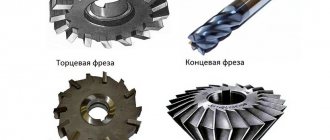
692D key-milling machine is designed for processing key grooves on shafts with measured and unmeasured end and key cutters and cutters manufactured according to TU2-035-858-82.
692D machine can process keyways with a width from 4 to 28 mm in a semi-automatic cycle.
Processing of grooves from 4 to 6 mm is carried out using a pendulum cycle with a measuring tool, and from 6 to 28 mm - to the full depth in one pass, followed by calibration of the width with a non-measuring tool.
The use of a device for calibrating the groove being processed on the machine ensures that the accuracy of the width of the keyway is maintained, regardless of the accuracy of the diameter of the cutters used (starting from a diameter of 6 mm).
On the 692D , the range of spindle speeds allows machining of keyways with both high-speed and carbide cutters over the entire range of slot widths with high productivity.
Machine design features
Longitudinal feed is carried out by moving the milling head along the guides of the bed head.
Vertical feed - spindle quill.
The groove is calibrated by moving the table transversely.
The drive of all listed movements is hydraulic. In addition, the machine has manual adjustment movements:
- longitudinal table;
- vertical table;
- vertical spindle quill;
- transverse head of the bed.
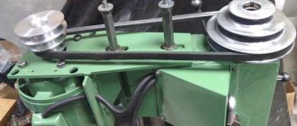
The spindle is driven by a 2.2 kW asynchronous electric motor through a gearbox and two-stage V-belt pulleys. The spindle speed is regulated by switching the gearbox handles and moving the V-belt on stepped pulleys from one stream to another.
Pendulum cycle of key-milling machine 692D
Keyways with a width of 4-6 mm are processed on a machine with a pendulum feed for plunging (pendulum cycle).
Keyways with a width of 6-25 mm are processed with drilling feed to the full depth and in one pass for the length of the groove (single-pass cycle).
To process precise keyways, the machine has a groove processing cycle with calibration of its width along two walls.
To process less precise grooves, there is a groove processing cycle with calibration of its width along one wall.
692D machine also has a groove processing cycle without calibration, when the width of the groove is provided by a cutter.
When cutting grooves to full depth, the drilling feed can be intermittent, which prevents the formation of long draining chips and its wrapping around the cutter.
In a pendulum cycle, the cutter is rapidly brought to the workpiece and moves along the workpiece at working feed. With each reversal of the longitudinal movement, the tool receives a periodic vertical infeed, the value of which is set on the dial and can range from 0 to 0.5 mm/stroke. After several longitudinal passes, the number of which will depend on the amount of vertical periodic feed, the groove will be cut to its full depth. It is possible to process a groove without calibration, with calibration of the groove width along one wall, with calibration of the groove width along two walls. The type of processing is selected using a switch on the machine console during setup.
The cycle without calibration ends after cutting the groove to a given depth, when the tool is quickly removed from the groove and moved to the beginning of the groove.
A cycle with calibration of the groove width along one wall is that after cutting a groove to a given depth, the workpiece is shifted perpendicular to its axis by the calibration amount, then the longitudinal calibrating feed is turned on and the tool processes one wall along its entire length, after which it is quickly removed from the groove .
The cycle with calibrating a groove along two walls differs from the previous one in that after cutting a groove to a given depth, the workpiece is shifted by half the calibrating movement, the tool processes one wall for its entire length, then the workpiece is shifted to the other side by the full amount of the calibrating movement and the tool processes the other wall of the keyway, after which the cutter accelerates upward, the milling head accelerates to its original position, the workpiece moves to the middle position, the cycle is completed.
A single-pass cycle differs from a pendulum cycle in that the tool, after an accelerated approach to the shaft with a continuous feed, mills the shaft to the full depth of the groove, and then, with a working feed, cuts the groove to a given length.
Once the groove has been cut to the specified length, there are three machining options, similar to those available in the pendulum cycle: without calibration; with groove width calibration along one wall; with calibration of the groove width along the two walls of the keyway.
The continuation of cycles after cutting a groove is the same as in the pendulum cycle.
The rotation speed and drive power of the main movement, the feed range and sufficient rigidity of the machine make it possible to process keyways with non-dimensional keyway cutters equipped with a hard alloy similar to cutters in accordance with GOST 6396-78, which significantly increases productivity compared to the processing of grooves with high-speed cutters.
Climatic modification and placement category of the machine UHL4 according to GOST 15150-69.
Modifications of the key-milling machine 692
692d - 1990.
Keyway width from 4 to 25 mm in a semi-automatic cycle, shaft diameter 12..75 mm 692r-1 - 1976. Key-milling machine
6d92r-1 - key-milling machine with a horizontal spindle
692r - 1975. Keyway width from 4 to 25 mm, depth up to 26 mm, length 5...300 mm. Shaft diameter 12..75 mm
6d92 - 1973. Keyway width from 6 to 32 mm. Horizontal spindle. Shaft diameter up to 120 mm.
692m - 1965. Keyway width from 4 to 24 mm, depth up to 40 mm, length 5...300 mm
692a - 1954. Keyway width from 3 to 20 mm, depth up to 26 mm, length 5...300 mm
Keyboard milling machine mod. 692D
Price: negotiable Order
Key-milling machine model 692D, designed for processing keyways with measured and non-measured key cutters.
The machine can process keyways with a width from 4 to 28 mm in a semi-automatic cycle.
Processing of grooves from 4 to 6 mm is carried out using a pendulum cycle with a measuring tool, and from 6 to 28 mm - to the full depth in one pass, followed by calibration of the width with a non-measuring tool.
The use of a device for calibrating the groove being processed on the machine ensures that the accuracy of the width of the keyway is maintained, regardless of the accuracy of the diameter of the cutters used (starting from a diameter of 6 mm).
On the 692D machine, the range of spindle speeds allows machining of keyways with both high-speed and carbide cutters over the entire range of slot widths with high productivity.
Equipment
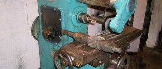
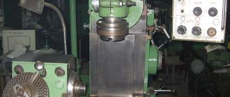
Photo of key-milling machine 692D
Photo of key-milling machine 692D
Photo of key-milling machine 692D
Photo of key-milling machine 692D
Photo of key-milling machine 692D
General view of the key-milling machine 692D
Photo of key-milling machine 692D
Photo of key-milling machine 692D
Photo of key-milling machine 692D
Photo of key-milling machine 692D
Photo of key-milling machine 692D
Other milling machines
Let's look at other milling machines that form a smaller group compared to the two examples described above.
1. Cantileverless milling machines (Fig. 5). They can be either with a vertical or horizontal spindle arrangement. They are used for simpler milling of metals and wood in terms of the complexity of the milling operations themselves. It does not have settings for the table lift height due to the lack of a console. The advantage is increased processing accuracy.
Figure 5. Cantileverless milling machine.
2. Longitudinal milling machine (Fig. 6). Designed for longitudinal milling of long parts or parts that require simple straight-line processing. These machines can also work with grinding wheels.
Figure 6. Longitudinal milling machine.
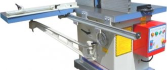
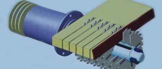
3. Key and milling machine (Fig. 7.). Designed for cutting keyways on workpieces of various shapes. Such machines operate in automatic mode after setting the keyway parameters.
Figure 7. Keyboard milling machine.
4. Gear hobbing machine (Fig. 8). Used to create teeth of various parameters. These machines use special cutters designed to create specific profiles of gears and worm gears.
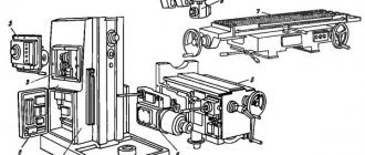
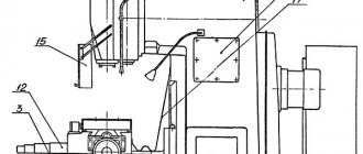
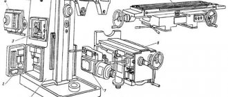
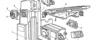
Arrangement of components of the key-milling machine 692D
Location of the main components of the 692D key-milling machine
Location of the main components of the 692D key-milling machine
Components of the key-milling machine 692D
- bed:
- gearbox;
- gearbox switching;
- milling head;
- casing;
- hydraulic equipment;
- hydroelectric station;
- hydraulic cylinder;
- console;
- emphasis;
- table;
- cooling;
- electrical equipment;
- electrical cabinet;
- accessories.
Types of Key Milling Machines
Based on the location of the spindles and their number, key milling machines are divided into horizontal and vertical, single-spindle machines and multi-spindle machines.
In Fig. Figure 2 shows a vertical two-spindle key milling machine DF-82D, operating with a measuring tool on a pendulum cycle. The machine has two spindle heads 1, a bed 4, a console 3, which can be manually moved vertically by 300 mm during adjustment, and a table 2 that can be moved transversely manually.
Technical characteristics of the machine 692D
| Parameter name | 692D | 692Р | 692M |
| Basic machine parameters | |||
| Accuracy class according to GOST 8-71 and GOST 8-82 | N | N | N |
| The largest diameter of the installed workpiece, mm | 12..75 | ||
| Processed groove width, mm | 4..25 | 4..25 | 4..24 |
| The greatest depth of the groove being machined in compliance with the requirements of GOST 23360-78 (GOST 7257-58, GOST 8788-68), mm | 9 | 10 | |
| Maximum total depth of the processed groove, mm | 26 | 26 | 40 |
| The largest diameter of the cutter installed on the machine, mm | 25 | ||
| Longitudinal movement of the milling head, mm | 5..400 | 5..300 | 5..300 |
| Maximum movement of the spindle sleeve by hand, mm | 100 | 100 | 100 |
| Maximum displacement of the spindle sleeve from the hydraulic drive, mm | 40 | 40 | 40 |
| Accelerated movement of the spindle sleeve from the hydraulic drive, mm | 14 | 14 | — |
| Dimensions of the working surface of the table (length x width), mm | 1000 x 250 | 1000 x 250 | 800 x 200 |
| Number of T-slots Dimensions of T-slots | 3 | 3 | 3 |
| Dimensions of the T-shaped middle slot, mm | 14N8 | 14A3 | |
| Dimensions of T-shaped outer slots, mm | 14N11 | 14A4 | |
| Installation longitudinal/vertical/lateral movement of the table manually, mm | 650/ 350 | 630/ 300/ 300 | 440/ 300/ 160 |
| Transverse movement of the table from the hydraulic drive (Value of the groove being processed during calibration), mm | 0,01..1,0 | 0,01..1,0 | — |
| Transverse installation movement of the spindle axis from the middle groove of the table in both directions, mm | ±5 | ±5 | |
| Internal spindle cone 7:24, according to GOST 24644-81 (GOST 15945-70) | 40 | 40 | KM3 |
| Number of spindle speed steps | 11 | 11 | 12 |
| Spindle speed, rpm | 400..4000 | 315..3150 | 375..3750 |
| Working feeds of the milling head - longitudinal, mm/min | 20..1400 | 250..1200 | 450..1200 |
| Working feeds of the milling head - vertical with a single-pass cycle, mm/min | 16..140 | ||
| Working feeds of the spindle sleeve for insertion - with a pendulum cycle, mm/min | 0,05..0,5 | 0,05..0,5 | 0,05..0,5 |
| Speed of rapid movement of the spindle sleeve (approach, retraction), mm/min | 200 | 200 | |
| Drive unit | |||
| Number of electric motors on the machine | 3 | 3 | 2 |
| Main motion drive electric motor, kW (rpm) | 2,2 (1500) | 2,2 | 1,1/ 1,6 (950/ 1440) |
| Hydraulic pump electric motor, kW (rpm) | 1,1 (1000) | 1,1 | — |
| Coolant pump electric motor, kW (rpm) | 0,12 (3000) | 0,12 | 0,125 (2800) |
| Total power of electric motors, kW | 3,42 | 3,42 | |
| Dimensions and weight of the machine | |||
| Machine dimensions (length width height), mm | 1615 x 1600 x 2210 | 2080 x 1640 x 1860 | 1520 x 1400 x 1750 |
| Machine weight, kg | 2250 | 1800 | 1250 |
- Avrutin S.V. Fundamentals of Milling, 1962
- Avrutin S.V. Milling, 1963
- Acherkan N.S. Metal-cutting machines, Volume 1, 1965
- Barbashov F.A. Milling business 1973, p.141
- Barbashov F.A. Milling work (Vocational education), 1986
- Blumberg V.A. Milling machine handbook, 1984
- Grigoriev S.P. Practice of coordinate boring and milling work, 1980
- Kopylov R.B. Working on milling machines, 1971
- Kosovsky V.L. Handbook of a young milling operator, 1992, p. 180
- Kuvshinsky V.V. Milling, 1977
- Nichkov A.G. Milling machines (Machinist's Library), 1977
- Pikus M.Yu. A mechanic's guide to repairing metal-cutting machines, 1987
- Plotitsyn V.G. Calculations of settings and adjustments of milling machines, 1969
- Plotitsyn V.G. Setting up milling machines, 1975
- Ryabov S.A. Modern milling machines and their equipment, 2006
- Skhirtladze A.G., Novikov V.Yu. Technological equipment for machine-building industries, 1980
- Tepinkichiev V.K. Metal cutting machines, 1973
- Chernov N.N. Metal cutting machines, 1988
- Frenkel S.Sh. Handbook of a young milling operator (3rd ed.) (Vocational education), 1978
Bibliography:
Related Links. Additional Information
- Milling machines: general information, classification, designation
- Comparative characteristics of cantilever milling machines of the 6N, 6M, 6R, 6T
- Feed box for console milling machines of the 6M : 6M12P, 6M13P, 6M82, 6M83, 6M82Sh, 6M83Sh
- Feed box for console-milling machines of the 6P : 6Р12, 6Р13, 6Р82, 6Р83, 6Р82Ш, 6Р83Ш Feed box for console-milling machines of the 6Т : 6T12, 6T13, 6T82, 6T83, 6Т82Ш, 6Т83Ш