Information about the manufacturer of the screw-cutting lathe DIP-300 (1d63, 1d63a)
In 1930, the Moscow Machine Tool Plant decided to develop a new standard lathe, abbreviated as TS. Somewhat later it was renamed DIP-200
–
Let’s catch up and surpass
, according to the main slogan of the first five-year plan, where 200 is the height of the centers above the frame.
from the German company VDF
was chosen as a prototype . In April 1932, preparations began for the release of the first batch of DIP-200 machines.
On April 25, 1932, the first Soviet universal screw-cutting lathe with a gearbox, DIP-200, was assembled and tested. By the end of 1932, 25 DIPs were produced.
In 1934, production of machines DIP-300 (1d63), DIP-400 (1d64), DIP-500 (1d65) was mastered.
Machine tools produced by the Moscow Machine Tool Plant Krasny Proletary, KP
- 1A62
- universal screw-cutting lathe Ø 400 - 1K62
- universal screw-cutting lathe Ø 400 - 1K62B
- universal screw-cutting lathe with increased accuracy Ø 400 - 1K282
- eight-spindle vertical lathe Ø 250 - 1K620
- universal screw-cutting lathe with variator Ø 400 - 1K625
- lightweight screw-cutting lathe with an increased line of centers Ø 500 - 16A20F3
– CNC lathe Ø 400 - 16B20P
- high-precision screw-cutting lathe Ø 400 - 16K20
– universal screw-cutting lathe Ø 400 - 16K20M
- mechanized screw-cutting lathe Ø 400 - 16K20P
- high-precision screw-cutting lathe Ø 400 - 16K20F3
– CNC lathe Ø 400 - 16K20F3S32
– CNC lathe Ø 400 - 16K20T1
- lathe with operational control Ø 500 - 16K25
- lightweight screw-cutting lathe with an increased line of centers Ø 500 - 162
— universal screw-cutting lathe Ø 420 - 1730
— semi-automatic multi-cutting lathe Ø 410 - DIP-40 (1D64)
- universal screw-cutting lathe Ø 800 - DIP-50 (1D65)
- universal screw-cutting lathe Ø 1000 - DIP-200
– universal screw-cutting lathe Ø 400 - DIP-300
– universal screw-cutting lathe Ø 630 - DIP-400
– universal screw-cutting lathe Ø 800 - DIP-500
– universal screw-cutting lathe Ø 1000 - MK6046, MK6047, MK6048
- universal screw-cutting lathe Ø 500 - MK6056, MK6057, MK6058
- universal screw-cutting lathe Ø 500 - MK-3002
- table lathe Ø 220
How to purchase “Catch up and overtake”?
DIP-300 has not been produced for a long time. It is difficult to buy a new model; only used ones are available. However, over more than half a century, many similar machines have been produced. Many of them have been preserved in excellent technical condition, while others have undergone major repairs. Thanks to its simplicity and reliability, restoring such a unit is quite simple, although costly.
Price is the first indicator of the condition of DIP-300. The cost of a functional modification starts from 180 thousand rubles. Anything that costs less than this amount is either in poor condition or does not function and requires repair.
The advantage is that there are a lot of spare parts for the machine on the market. The DIP-300 unit is suitable for parts from subsequent modifications, as well as from modern machines that are produced today.
If you have the necessary knowledge, skills and appropriate equipment, it is even more profitable to buy a DIP-300 for restoration.
When purchasing DIP-300, pay attention to:
— the condition of the chuck, especially the jaws, for clamping reliability;
— operability of the lubrication system;
— the condition of the guides, affecting the accuracy of work;
— spindle rotation, no runout.
It’s easy to find for purchase via the Internet, where there are many platforms for selling used units. The most popular of them is Avito, a free classifieds site. The price depends on the date of its production, technical condition and wear of components, as well as on the specific modification. New models, for example, 1M63M or 1M63N, have greater capabilities and are more expensive.
The DIP series of screw-cutting lathes has been produced at the Ryazan Machine Tool Plant since 1956. This line also consists of many modifications of equipment DIP-200, 300 and 500, which we will discuss in this article.
The material will discuss the design features and technical characteristics of the equipment, its functionality, advantages and disadvantages, and also present relevant diagrams and drawings.
DIP-300 universal screw-cutting lathe. Purpose and scope
The universal screw-cutting lathe model DIP-300 (according to the classification ENIMS 1d63 ) is the first Soviet machine with a gearbox and a processing diameter above the bed of 615 mm, like all other DIPs ( DIP-200
, DIP-300, DIP-400, DIP-500), developed and produced at the Moscow machine-tool plant Krasny Proletary from 1930 to the 1950s.
DIP-300 screw-cutting lathe is designed to perform a wide variety of work on centers, collet or jaw chucks for ferrous and non-ferrous metals, including turning cones, as well as for cutting metric, modular, and inch threads.
The DIP-300 lathe is capable of processing relatively large workpieces with a diameter of up to 615 mm and a length of 1500 or 3000 mm.
Operating principle and design features of the machine
The front end of the spindle is threaded M120 x 6, the internal Morse taper is 5, the hole in the spindle is 70 mm, the diameter of the processed rod is 68 mm.
The spindle of the DIP-300 (1d63a) machine is mounted on double-row roller bearings at the front and in a tapered roller bearing at the rear. The axial load on the spindle is carried by a thrust ball bearing.
The spindle receives 18 stages of forward and reverse rotation frequencies from a six-shaft gearbox in the headstock of the machine. Setting the desired speed is carried out by three handles on the front wall of the headstock.
Starting, stopping and activation of accelerated reverse motion is carried out by a friction plate clutch. The clutch is controlled by handles on the frame at the headstock and on the apron.
The motion is supplied to the input shaft of the gearbox through a belt drive from an asynchronous electric motor with a power of 10 kW.
The feed box receives movement from the gearbox through the guitar - replaceable gears with an angle. The headstock includes mechanisms that make it possible to change the direction of movement of the caliper and speed up this movement (increase the thread pitch) by 4 and 16 times.
To produce high-precision threads, the lead screw can be connected through the guitar's replacement gears in addition to the feed mechanism.
The caliper receives feeds along the running roller: longitudinal from 0.10 to 1.6 mm and transverse from 0.04 to 0.59 mm per spindle revolution.
support apron the DIP-300 (1d63a) lathe is equipped with a falling worm mechanism, which makes it possible to automatically turn on the feed from the lead screw when cutting threads in both directions and at the same time protects the machine from damage in case of overload. Disconnection is carried out with an accuracy of 0.02 mm from the stop on the frame.
History of the screw-cutting lathe DIP-300
In 1930, the Moscow Machine Tool Plant decided to develop a new standard lathe, abbreviated as TS. Somewhat later, it was renamed DIP-200
-
Let's Catch Up And Overtake
, according to the main slogan of the first five-year plan, where 200 is the height of the centers above the frame.
from the German company VDF
was chosen as a prototype . In April 1932, preparations began for the release of the first batch of DIP-200 machines.
On April 25, 1932, the first Soviet universal screw-cutting lathe with a gearbox, DIP-200, was assembled and tested. By the end of 1932, 25 DIPs were produced.
IN 1934
This year, the Moscow Machine Tool Plant mastered the production of heavy universal screw-cutting lathes DIP-300 (1d63), DIP-400 (1d64), DIP-500 (1d65).
IN 1944
year, the production of these machines was transferred to
the Ryazan Machine Tool Plant RSZ , founded in 1944, the Tbilisi Machine Tool Plant named after. Kirov and Yeisk Machine Tool Plant .
In 1956
The Ryazan Machine Tool Plant produced the first industrial batch of machines of the DIP-300 series - model 163 - RMC 1400, 2800.
IN 1968
The next generation of the series was launched into production - model 1m63, 1m63B.
WITH 1973
year, the beginning of serial production of lathes: 16K30, 16K30F3, 1M63Bf101, 16M30F3, 1P756DF3.
Tbilisi Machine Tool Plant named after. Kirov produced machines: 1D63A, 1M63D, 1M63DF101.
IN 1992
year, the start of serial production of the
1M63N , the latest model of the DIP-300 series.
Principle of operation
For thread cutting, switching to a special feed shaft is structurally provided.
Its control is located to the left of the worker on the body. The switching dial allows you to select the thread pitch in the metric or inch system. The shape is determined by the configuration of the cutter. Transverse feed regulates the diameter and depth of processing. Modern machines of domestic and foreign production use the same principle. It is considered the most reliable and productive. Rapid feed reduces operation time. In terms of productivity, DIP 500 is not much inferior to modern analogues, with the exception of CNC equipment. During the production of the DIP 500 machine, some modifications took place. Individual batches of equipment may have a bed length different from the standard and a set of additional accessories. The changes also affected some mechanical details. This must be taken into account during operation. In case of repair, replacement only with an original analogue is allowed. It is not recommended to purchase spare parts of dubious manufacture, or made under conditions not intended for the manufacture of elements of the mechanical part of the machine. This will reduce the quality of work and can become a source of danger for the turner. The most critical option is considered to be failure of the frame. It will not be possible to adequately replace or repair it.
Read also: DC-DC voltage converter
Considerable attention is paid to employee safety. Protective covers over moving parts, guardrails
Emergency stop system in case of breakdown or jamming.
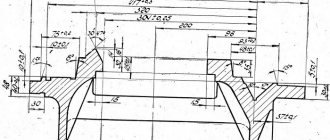
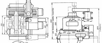
Landing and connecting bases of the lathe DIP-300 (1d63a)
Sketch of the end of the spindle of the machine DIP-300 (1d63a)
Bed of screw-cutting lathe DIP-300 (1d63a)
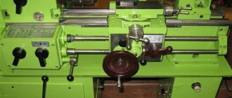
General view of the screw-cutting lathe DIP-300 (1d63a)
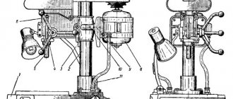
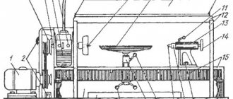
Photo of screw-cutting lathe DIP-300 (1d63a)
Photo of the headstock of the screw-cutting lathe DIP-300 (1d63a)
Photo of the headstock of the screw-cutting lathe DIP-300 (1d63a)
Photo of the headstock of the screw-cutting lathe DIP-300 (1d63a)
Design features of the machine
The machine has a configuration that is traditional for equipment of this class, allowing it to perform all the necessary operations for processing workpieces. If there is a need to purchase this type of equipment, then during the pre-sale inspection it is better to take with you a specialist who will determine the authenticity of the parts or confirm the validity of replacing them with others, without loss of quality.
Components of a lathe
Load-bearing parts of the equipment are made of cast iron. The characteristics of the alloy are optimal for long-term operation. Special processing methods during production made it possible to obtain a design that is resistant to shock and vibration loads. The machine has a stable geometry and the necessary strength. The product consists of the following elements:
- Bed. One-piece construction with high-precision processing of functional units, sliding surfaces, and basic geometric points;
- Headstock. An element for fixing a part, giving it rotation, adjusting technical processing parameters;
- Tailstock. Performs the function of supporting long parts during processing and accurately fixing them in space. A cutting tool is attached to the tailstock for making holes and performing other operations;
- Power point. The engines allow full control of cutting speed, feed, thread pitch;
- Electrical diagram. The machine is equipped with an adjustment system, overload protection, lighting, and lubrication.
The equipment is supplied with two steady rests, movable and fixed for high-quality processing of long parts, preventing vibrations, and obtaining precise geometry of products. The tailstock moves along the frame using a gearbox and a rotating handle. A separate built-in, adjustable shaft allows you to fix the center cutting tool. The powerful body, successful architecture of the machine, and high requirements in the production of parts for it allowed the product to be used for many decades.
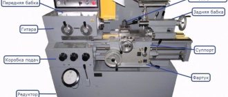
Location and purpose of controls
The design of the machine allows the worker to quickly configure the equipment to solve the upcoming task. The main controls are located to the left of the turner on the machine body. These include:
- Machine on/off button;
- Limb for switching the rotation speed of the working spindle;
- Shift handle for threaded feed shaft;
- Pitch adjustment dials for inch, metric, modular threads;
- Handles for setting the speed of longitudinal and transverse feed.
The feed mode switch is installed on the support. It has two positions. In the first, the forced feed clutch is activated, in the second, control is carried out manually. The design of the support has additional slides for a four-position tool holder with independent adjustment of lateral movement for the production of cones and parts of complex shapes. Standard 4-jaw chuck, diameter 100 mm.
Location of controls for screw-cutting lathe DIP-300 (1d63a)
Location of controls for screw-cutting lathe DIP-300 (1d63a)
Specification of controls for screw-cutting lathe DIP-300 (1d63a)
- Handle for setting the spindle speed
- Handle for setting the spindle speed
- Handle for reversing the caliper stroke
- Handle for increasing thread pitch
- Handle for setting the spindle speed
- Handle for installing Whitworth and metric threads
- Handle for setting thread pitch
- Feed shift knob (Norton cone)
- Handle for installing metric and modular threads
- Handle for turning on the lead screw or shaft
- Handle for turning on and reversing the machine
- Handle for reversing the travel of the caliper during turning
- Handwheel for manual longitudinal movement of the caliper
- Handle for turning off the feed and turning it on after automatic installation
- Handle for switching longitudinal and transverse feed and locking the lead screw nut
- Handle for turning on the lead screw nut
- Handle for turning on and reversing the machine
- Handle for manual cross feed of caliper
- Handle for securing the cutting head
- Handle for feeding the cutting sled
- Handle for securing the tailstock quill
- Push button station
User manual
It is very important to follow the instructions when operating. Simple rules contribute to the longevity and proper functioning of the machine.
For safety reasons, the following is required:
— check the technical safety equipment: the guard of the main drive and replaceable gears, the introductory automatic switch on and off, the chip protection device, the “stop” buttons and the shut-off device for moving the caliper;
— ensure reliable fastening of the workpiece;
— in the first period after start-up, do not turn on the maximum spindle rotation speed;
— when processing long parts, use steady rests;
— Reverse the spindle only when completely stopped, do not switch the gears of the headstock and feedbox while moving;
- do not touch rotating parts and parts with your hands, tuck in clothes to avoid being pulled in by rotating parts - the lead shaft, lead screw and other parts.
To obtain the specified accuracy of the machine, you need to install it correctly. Installation must be carried out on a concrete floor with alignment on two planes using levels. After alignment, the foundation bolts are tightened and filled with cement mortar. To improve stability, cement mortar is poured under the bed frames.
All standard thread sizes correspond to the settings indicated on the headstock labels. To cut non-table threads, you must use the machine setting formulas given in the passport. All caliper adjustment and adjustment diagrams with examples of calculating the cone groove are also indicated in the passport.
Control of screw-cutting lathe DIP-300 (1d63a)
Gearbox
Depending on the working position, starting, stopping and changing the direction of rotation of the spindle is done by handle 11 at the headstock or handle 17 at the apron. These handles control the two-way slip plate clutch and brake located inside the gearbox. The brake operates automatically in the middle disengaged position of the clutch, ensuring a quick stop of the gearbox mechanism and spindle. When moving the indicated handles to one of the extreme positions, you need to slowly move them to the middle position, and then vigorously move them to the desired extreme position.
To change the spindle rotation speed, handles 1, 2 and 5 need to be moved only at low speed or when the machine is stopped.
Gearbox
Feeds and threads are set with handles 6(A), 7(B), 9(C) and the Norton cone switch 8 according to the table located on the cover of the box. The lead screw or lead roller is turned on using handle 10(D). To directly transfer rotation from the guitar to the lead screw, the feed box is turned off with handle 6(A), and handle 7(B) is placed in the middle position. This may be necessary when cutting high-precision threads or with a special pitch using a special set of replacement gears on the guitar. It is possible to rearrange the feed box handles only at low speed.
Apron and caliper
The caliper feed mechanisms are turned on and off by the handle 14 of the falling worm located inside the apron. Manual feed of the caliper is carried out using handles 18 and 20.
Automatic shutdown of the longitudinal and transverse feed of the caliper is carried out using a falling worm mechanism at the moment of overload under the influence of a large cutting force, or other resistance (focus on the frame) along the feed direction. This mechanism protects the machine from damage and makes it possible to obtain precise dimensions of the product when working against the stop. For this purpose, rotation is transmitted to the worm and worm wheel from the worm shaft through a coupling sitting on the shaft, which engages with its screw protrusions on the worm with the same protrusions of the worm under the action of spring pressure. When the resistance in the transmission system of the caliper and apron increases, reaching a value for which the adjusted spring pressure on the clutch is not designed, the worm shaft, continuing to rotate, will force the clutch, through the screw protrusions of the worm, to push away from it and compress the spring.
During this movement of the coupling along the roller, it turns the lever with handle 14, which supports the worm in a raised position and engaged by the worm gear; the worm falls and disengages from the gear. To turn on the feed, the worm is engaged with the gear by lifting it using handle 14.
When securing the tool holder head of the caliper with handle 19, it is necessary to ensure that the fixing pin fits into the hole on the lower plane of the head. This pin should not be removed, since it helps ensure correct installation of the head. To secure the support to the frame when turning transversely or turning the upper part of the support, it is necessary to tighten the clamping bar of the bed guides with a bolt with a protruding square head on the part of the carriage in front of it on the right side.
Tailstock
Transverse movement of the tailstock body along the bridge, necessary when turning conical products, is carried out using 2 screws 1 on the front and rear sides in the lower part of the body. After loosening screw 2, which presses the transverse front guide plane of the housing groove to the protrusion of the bridge, loosen the screw on the side where you want to move the headstock, and tighten the opposite screw 1. Screw 2 is tightened again after installation is complete. Setting the center of the headstock exactly in the center of the spindle is done by aligning the marks on the “K” plates located on the back side of the bridge and the headstock body. In relation to the bridge, the headstock can be shifted by 10 - 15 mm. To move the tailstock quill, you must first use handle 21 (see control diagram) to release the clamp with which the quill is secured when working in the centers.
Emphasis
A stop, adjustable and fixed on the bed, is provided for turning a product to a certain length during longitudinal turning by automatically turning off the feed when it comes into contact with the carriage stop. The emphasis is installed on the frame guides at the beginning by eye and is strengthened with a clamping screw, and then the adjustment screw is used for precise installation.
Description
This unit has quite a lot of weight and large dimensions. Designed for working with metal parts of large and medium sizes. The DIP300 lathe is one of the most popular models; it can perform the following functions:
- internal and external turning, including processing of cone-shaped parts;
- boring;
- drilling;
- metric, inch or modular thread cutting.
Note! All units in this series have the ability to mechanically move the upper part of the caliper, making it possible to sharpen and process cones of considerable length. And the caliper itself moves in two directions - transverse and longitudinal.
Adjusting the working parts of the machine
Adjusting the spindle bearings of the screw-cutting lathe DIP-300 (1d63a) (Fig. 1)
Adjusting the spindle bearings of the machine DIP-300 (1d63a)
Adjusting the spindle bearings of the machine DIP-300 (1d63a)
The front conical journal of the spindle rotates in a special adjustable double-row roller bearing with cylindrical rollers. To obtain play, the front spindle bearing is adjusted from inside the headstock by tightening the inner ring of bearing 1 using nut 2.
Adjustment of the rear tapered bearing 3 together with the thrust ball bearing 4 is carried out from the outside of the headstock using nuts 5. After adjusting the bearings, you should check the spindle for radial release. To do this, a mandrel with a conical tail (80 metric cone) and a long cylindrical part of 50 - 55 mm of at least 300 mm is inserted into the conical hole of the spindle.
The tip of the indicator is brought to the centering neck of the spindle and the spindle is pressed out manually using the cylindrical end of the mandrel. In this case, the deviation of the indicator needle should not exceed 0.015 mm. In addition, the spindle should be easily turned by hand if the clutch is placed in the on position.
The front spindle bearing No. 3182128 has main dimensions of 140 x 210 x 53.
Lubrication of the spindle bearings is ensured by the flow of oil when splashed into the existing recesses in the upper part of the gearbox.
Adjusting the friction plate clutch of the gearbox (Fig. 2)
If the friction clutch slips during the working stroke, it must be adjusted immediately, because the friction of the discs will heat up greatly and the machine will not work normally. The friction clutch is adjusted using pressure nuts 1 screwed onto ring 2. The pressure nut can be rotated only after the latch 3 is pressed into ring 2. When the clutch is engaged, one of the ends of the rocker arm 4 must be under the horizontal plane of the groove of the shift clutch 5 .
Model range of machines of the DIP series
The DIP line of metalworking turning equipment consists of 4 machine models:
- DIP 200;
- DIP 300;
- DIP 500;
- 1m61 (universal).
Let's take a closer look at each of the presented varieties.
2.1
Of all the modifications of turning units, the DIP 200 machine is distinguished by the most compact dimensions. This device has an optimal combination of a rigid frame and engine power, which ensures a minimum level of vibration during operation and, as a result, the possibility of high-precision semi-finishing and finishing processing of workpieces made of metal, cast iron or non-ferrous alloys.
Technical characteristics of DIP 200:
- the height of the centers is 20 cm, the distance between the centers is 75, 100 and 150 cm;
- spindle speed - 16-20 rpm;
- number of speeds - 18 pcs;
- longitudinal feed stroke of the caliper - from 0.12 to 2.15 mm/rev, transverse - from 0.03 to 0.55 rpm;
- engine power - 3700 W.
In terms of operational characteristics - speed, feed range and drive power, the DIP 200 was significantly inferior to most lathes of that time, which causes this model to go out of use quite quickly. Critical shortcomings also include the lack of a coolant supply system and a mechanism for accelerated movement of the caliper.
2.2
Unlike the 200th model, the DIP 300 machine can be found in factories or metalworking shops to this day. The reason for this is the reliability and durability of the design, as well as good technical characteristics that allow high-speed boring, drilling, threading and turning.
The DIP 300 machine belongs to the group of large-sized turning equipment, its weight is 4.3 tons, and the dimensions of the working surfaces allow processing workpieces with a diameter of up to 900 mm and a weight of 2 tons. This model has a second electric motor, which is responsible for the longitudinal-transverse movement of the support. The power of the main drive is 13000 W, the speed is 18-1800 per minute.
The characteristic features of the DIP 300 machine are:
- increased spindle rotation speed in reverse (1.3 times relative to normal), which provides the possibility of accelerated thread cutting;
- the presence of two prismatic guides on the frame, increasing the spatial rigidity of the structure;
- the gearbox is equipped with electromagnetic clutches, allowing you to change the spindle speed without turning off the drive;
- increased operational safety due to the presence of a chuck guard and an electrical spindle locking system.
The support of this machine is made in a cross-shaped configuration. Its movement in the longitudinal longitudinal plane occurs along the frame guides, and in the transverse plane - along the carriage guides. The DIP 300 spindle is hollow, its speed is adjusted manually using a handle mounted on the gear shaft of the gearbox.
2.3 DIP-500
The DIP-500 machine is an industrial turning equipment designed for use in small- and medium-scale production. The installation has the following functionality:
- boring;
- turning;
- thread cutting;
- drilling;
- cone processing.
Unlike the 200 and 300 models, the DIP 500 machine is equipped with a closed gearbox. The maximum weight of processed parts has also increased significantly - up to 5 tons, and their dimensions: diameter up to 100 cm, length up to 8 meters.
This unit is equipped with two motors - an auxiliary motor with a power of 1.5 kW, which ensures automatic movement of the caliper, and a main motor with a power of 4 kW. The device is also equipped with two pumps: PA-22 - for supplying coolant, and S12-54 - for lubricants. The electrical circuit of the machine is shown in the image.
The gearbox is responsible for moving the tailstock along the guide frame. The machine spindle is mounted on three rolling bearings (two adjustable, one fixed); it moves by manual rotation of the flywheel.
2.4 1M61 (screw-cutting lathe)
One of the modifications of the DIP series equipment was the 1M61 multifunctional machine. According to the class of processing accuracy, it belongs to group “N” in accordance with the provisions of GOST No. 8-82. This unit has the following technical characteristics:
- maximum diameter of the workpiece being processed is 320 mm, length is 1000 mm;
- turning length - up to 640 mm;
- height of centers - 170 mm;
- spindle speed - from 12 to 1600 rpm;
- tailstock quill travel is 100 mm.
1M61 is equipped with two electric motors: a 4000 W main motor and a 120 W cooling pump drive.
Initially, the DIP-300 lathe, which began production in 1932, was intended for processing wooden products, and later, having undergone changes, it began to be used for processing metal blanks. The development of mechanical engineering in the post-revolutionary Soviet Union was gaining rapid momentum, following the European one, due to which a unique machine appeared, which in its characteristics was ahead of its foreign analogues.
Its name is an abbreviation of the phrase “Catch up and overtake.” The numbers used in the name of the unit indicate the height of the centers. The characteristics inherent in the installation made it one of the most common in the Soviet Union and neighboring countries. The model has a wide range of capabilities and allows you to work with blanks made of ferrous and non-ferrous metals.
Adjusting the lateral movement of the tailstock of the screw-cutting lathe DIP-300 (1d63a)
Adjusting the lateral movement of the tailstock of the DIP-300 (1d63a) machine
Elimination of slack (play) in the guides of the lower and upper support of the screw-cutting lathe DIP-300 (1d63a)
Elimination of slack in the guides of the support of the machine DIP-300 (1d63a)
When play appears, the corresponding wedges 1 or 2 are tightened using screws 3 and 4 screwed into the ends of the upper and lower parts of the caliper.
Adjusting the vertical clearance in the rear guide of the slide carriage of the screw-cutting lathe DIP-300 (1d63a)
Adjusting the gap in the slide carriage guide of the machine DIP-300 (1d63a)
The gap between the rear guide of the carriage and the frame is adjusted by tightening the strips 1 with screws 2 and fixing the latter with lock nuts 3. After adjustment, the gap should be no more than 0.02 mm.
Elimination of the backlash of the screw for the transverse movement of the support of the screw-cutting lathe DIP-300 (1d63a)
Elimination of backlash of the screw for transverse movement of the support of the DIP-300 (1d63a) machine tool
The “backlash” of the caliper cross-stroke screw, which occurs when the nut is worn, can be eliminated by tightening the wedge 3 inserted between the nut halves. First you need to loosen screw 1 and after selecting the backlash, tighten it again. The “backlash” of the cross-feed screw should be no more than two dial divisions.
Adjusting the tension of the spring of the falling worm of the apron of the screw-cutting lathe DIP-300 (1d63a)
Elimination of slack in the slide guides of the screw-cutting lathe DIP-300 (1d63a)
The pressure of spring 1 on the clutch of the falling worm with its shaft is adjusted by tightening or loosening nut 2 screwed onto the right end of this shaft. When the pressure decreases, the nut should move along the shaft to the right, and when the pressure increases, it should move to the left. When adjusting the spring, do not allow it to be fully compressed “turn to turn”, since in this case the safety clutch loses its purpose and damage to the apron and caliper mechanisms may occur in case of overload. It is recommended to adjust the spring pressure in accordance with the cross-section of the chips removed during processing.
Adjusting the clearance of the guide of the upper and lower halves of the master nut of the lead screw of the DIP-300 (1d63a) screw-cutting lathe
Adjusting the gap of the mother nut of the lead screw of the machine DIP-300 (1d63a)
When play appears, the strap 1 is tightened with screws 2 and secured with locknuts 3.
Limiting the proximity of the upper and lower halves of the lead screw nut of the screw-cutting lathe DIP-300 (1d63a)
Limiting the proximity of the mother nut of the lead screw of the DIP-300 (1d63a) machine
The necessary freedom of rotation of the screw when the nut is engaged without excessive axial clearance between the threads of the screw and the nut is achieved by moving the thrust pin 1, located in the vertically drilled hole in the lower half of the nut using the screw 2 located below. The screw is fixed with a lock nut 3.
Adjusting the brake band of the gearbox
This is done by changing its tension using the nuts of a bolt attached to the end of the tape. The nuts are located at the top of the rear outer side of the gearbox housing. The adjustment must be made with the electric motor turned off, checking at low speed the braking force and the loosening of the belt when the friction clutch is in the engaged position, both during forward and reverse motion. When checking, the electric motor turns on.
Connection and safety when working with equipment
Any machines require preliminary checks before use. A cluttered desktop with unnecessary details is eliminated. The operation of the main drive begins after using the start button at the feed unit. On the carriage instrument panel there is another button, an additional one. The main thing is that the clutch remains in the off position for the most part.
If the device is damaged, it must be sent for restoration work. Technical documentation is also supplied to the service so that there are no problems finding spare parts.
Electrical circuit diagram of the screw-cutting lathe DIP-300 (1d63a)
Electrical diagram of the screw-cutting lathe DIP-300 (1d63a)
The machine has 2 electric motors:
- Main drive electric motor 1M, three-phase asynchronous, squirrel-cage rotor, power 10 kW, 1450 rpm, type A61-4
- Cooling pump electric motor 2M, power 0.125 kW, 2800 rpm, pump P-22
Advantages and disadvantages of the 1M63 machine
Complex and rounded metal surfaces are what this type of equipment was created for processing. It is when performing such work that it shows its best qualities. Safe operation of the machine is guaranteed thanks to special guards and other similar protective elements. The device is characterized by temperature stability and rigidity, vibration resistance, and reliability.
The disadvantages include the serious weight of the installation and problems with finding some parts.
Technical characteristics of screw-cutting lathes DIP-300 (1d63a)
| Parameter name | DIP-300 1D63A | 163 |
| Main settings | ||
| Accuracy class according to GOST 8-82 | N | N |
| The largest diameter of the workpiece above the bed, mm | 615 | 630 |
| The largest diameter of the workpiece above the support, mm | 345 | 340 |
| Center height, mm | 300 | 315 |
| Maximum workpiece length (RMC), mm | 1500, 3000 | 1400, 2800 |
| Maximum turning length - machining over a support without rearranging the cutting slide, mm | 1310, 2810 | 1260 |
| Largest cutter dimensions, mm | 30 x 30 | 40 x 40 |
| Height from the cutting surface to the center line, mm | 32,5 | 40 |
| Maximum distance from the center line to the edge of the tool holder, mm | 325 | 320 |
| Spidel | ||
| Diameter of through hole in spindle, mm | 70 | 70 |
| Maximum rod diameter, mm | 68 | 65 |
| Number of speed steps for direct spindle rotation | 18 | 24 |
| Spindle direct rotation frequency, rpm | 14..750 | 10..125 |
| Number of spindle reverse rotation frequency steps | 18 | 18 |
| Spindle reverse rotation frequency, rpm | 22..945 | 18..1800 |
| Size of the internal cone in the spindle, M | Morse 5 | Morse 5 |
| Spindle end | M120 x 6 | GOST 12593 |
| Spindle braking | There is | There is |
| Caliper. Submissions | ||
| Maximum stroke length of the carriage by hand, mm | 1510, 3010 | 1260, 2520 |
| Maximum stroke length of the carriage along the roller, mm | 1310, 2810 | 1260, 2520 |
| Maximum stroke length of the carriage along the screw, mm | 1310, 2810 | 1260, 2520 |
| Number of longitudinal feed stages | 26 | 32 |
| Limits of longitudinal working feeds, mm/rev | 0,15..2,65 | 0,10..1,6 |
| Number of cross feed stages | 26 | 32 |
| Limits of working cross feeds, mm/rev | 0,05..0,9 | 0,04..0,59 |
| Transverse movement per dial division, mm | 0,05 | 1 |
| Transverse movement of the caliper per one revolution of the dial, mm | 5 | |
| Longitudinal movement per dial division, mm | 1 | |
| Longitudinal movement of the caliper per one revolution of the dial, mm | 300 | |
| Speed of fast movements of the caliper, longitudinal, m/min | No | 3,6 |
| Speed of fast movements of the caliper, transverse, m/min | No | 1,3 |
| Number of metric threads to be cut | 79 | |
| Limits of pitches of cut metric threads, mm | 1..224 | 1..192 |
| Number of inch threads to be cut | ||
| Limits of pitches of cut inch threads | 2..28 | 24..1/4 |
| Number of modular threads to be cut | ||
| Limits of pitches of cut modular threads | 0.25p.. 56p | 0.5p..48p |
| Number of cut pitch threads | No | 96..7/8 |
| Limits of pitches of cut pitch threads | No | |
| Lead screw pitch, mm | 12 | |
| Switching stops | No | No |
| Cutting slide | ||
| Maximum movement of the cutting slide, mm | 220 | |
| Movement of the cutting slide by one division of the dial, mm | 0,05 | 0,05 |
| Movement of the cutting slide per one revolution of the dial, mm | 5 | |
| Number of stages of cross feed of the cutting slide | No | 32 |
| Limits of working feeds of cutting sleds, mm/rev | No | 0,033..0,50 |
| Angle of rotation of the cutting slide, degrees | +90; -45 | |
| Tailstock | ||
| Cone | Morse 5 | Morse 5 |
| Maximum movement of the quill, mm | 205 | 225 |
| Lateral displacement, mm | ±15 | ±10 |
| Electrical equipment | ||
| Number of electric motors on the machine | 2 | |
| Main drive electric motor power, kW | 10 | 14 |
| Cooling pump electric motor power, kW | 0,12 | |
| Cooling pump (pump) | PA-22 | |
| Dimensions and weight of the machine | ||
| Machine dimensions (length width height), mm | 3610 x 1690 x 1275 5110 x 1690 x 1275 | 3550 x 1740 x 1275 4950 x 1740 x 1275 |
| Machine weight, kg | 3920 | 3800 5000 |
- Universal screw-cutting lathe 1D63A. Passport, Tbilisi, 1953
- Acherkan N.S. Metal-cutting machines, Volume 1, 1965
- Batov V.P. Lathes., 1978
- Beletsky D.G. Handbook of a universal turner, 1987
- Denezhny P.M., Stiskin G.M., Thor I.E. Turning, 1972. (1k62)
- Denezhny P.M., Stiskin G.M., Thor I.E. Turning, 1979. (16k20)
- Modzelevsky A. A., Muschinkin A. A., Kedrov S. S., Sobol A. M., Zavgorodniy Yu. P., Lathes, 1973
- Skhirtladze A.G., Novikov V.Yu. Technological equipment for machine-building industries, 1980
- Tepinkichiev V.K. Metal cutting machines, 1973
- Chernov N.N. Metal cutting machines, 1988
- Pikus M.Yu. A mechanic's guide to machine repair, 1987
Bibliography:
Related Links. Additional Information
- Classification and main characteristics of turning
- Selecting the right metalworking machine
- Multi-start thread. Methods for cutting multi-start threads on a lathe
- Graphic signs for lathes
- Friction clutch of a screw-cutting lathe
- Lathe repair technology. Repair of bed and support guides
- Lathe repair technology. Repair of headstock and tailstock
- Lathe spindle repair
- Methodology for checking and testing screw-cutting lathes for accuracy
- Directory of lathes
- Manufacturers of lathes
Home About the company News Articles Price list Contacts Reference information Interesting video KPO woodworking machines Manufacturers
Equipment
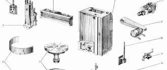
The machine kit includes the following items:
- protective casing;
- gearbox;
- electric motor;
- bed;
- front and rear stock;
- add. fencing;
- electrical group equipment;
- apron;
- caliper;
- gears.
There is also a passport along with the instruction manual.