Information about the manufacturer of the educational screw-cutting lathe TVSh-3 (TV-3)
Manufacturers of the screw-cutting lathe model TVSh-3 are the Engels Technical College, Correctional Labor Institutions for Minors (TCN), Verkhneturinsky Machine-Building Plant.
TVSh-3 (TV-3) the first school screw-cutting lathes, produced in the 60s of the last century. The design of the machine was apparently based on a German-made machine. In the 70s, the TVSh-3 model was replaced by a more advanced screw-cutting lathe - TV-4 .
School machines
- NS-16 - tabletop drilling machine Ø 16
- NGF-110Sh3 - low power milling machine 0.6 kW, table size 100x400 mm
- NGF-110Sh4 - low power milling machine 0.75 kW, table size 100x400 mm
- SNVSH - tabletop drilling machine Ø 16
- SNVSH-2 - tabletop drilling machine Ø 16
- TV-4
- educational screw-cutting lathe Ø 200, RMC 350 mm - TV-6
- educational screw-cutting lathe Ø 200, RMC 350 mm - TV-6M
- educational screw-cutting lathe Ø 200, RMC 350 mm Dubno - TV-7
- educational screw-cutting lathe Ø 220, RMC 330 mm - TV-7M - educational screw-cutting lathe Ø 220 mm, RMC 275 mm
- TV-9 - educational screw-cutting lathe Ø 220 mm, RMC 525 mm
- TV-11 - educational screw-cutting lathe with frequency converter Ø 240, RMC 750 mm
Characteristics and parameters
TVSh 3 first appeared in the early sixties of the 19th century on the territory of modern Germany. Some of the documents regarding the equipment were lost, but experts assure that at that time the machine was massive and heavy. Since the 70s, TVSh 3 has become smaller in size. Modern versions of turning equipment are lightweight and easy to install; they are used not in professional activities, but for conducting training courses for beginners.
The purpose of the device is to teach turning. A screw-cutting machine allows you to comfortably perform most turning operations, with a minimal degree of error. The fact that it is intended primarily for training is determined by its high degree of safety. Compared to other lathes that are used for identical activities, the risk of injury is many times lower. This quality is ensured by special design changes in the equipment.
Using a lathe, various operations related to material processing are performed. The most common:
- the ability to grind even cones from the material,
- carving with rectangular and square lines,
- formation of bars and beams,
- cutting material,
- cutting off pieces of material to the required size,
- processing the ends of already turned products,
- production of through holes of the selected diameter,
- drilling blind holes.
Of course, in comparison with professional machines, the school version has a limited set of functions. It allows you to carefully examine how the mechanism works, form smooth parts, and thereby hone your level of skill. Students of turning will learn how the tailstock is adjusted, how the cutter works, and what additional parts the lathe is equipped with. In professional models, which are intended for large productions, this is impossible to trace.
The technical characteristics are fully consistent with the intended purpose. The operating sheet states that:
- the maximum diameter of the part that is installed under the caliper area does not exceed 9 centimeters,
- the maximum diameter of the part that is installed above the frame is up to 10 centimeters,
- center-to-center size - 35 centimeters,
- setting the center axis - up to 19 centimeters,
- the maximum diameter of the workpiece being processed is up to 1.4 centimeters (for a rod),
- turning length - 35 centimeters,
- maximum caliper displacement is adjusted - 10 centimeters,
- maximum longitudinal displacement of the caliper is 30 centimeters,
- number of revolutions - from 120 to 170,
- number of speeds - three,
- number of gearbox shift stages - six,
- power - up to 600 W.
The height of the TV 3 lathe is 101 centimeters, length - 143 centimeters, and width - 470 centimeters. The weight without the installed cartridge is about 280 kilograms.
TVSh-3 (TV-3) Training screw-cutting lathe. Purpose, scope
The TVSh-3 screw-cutting lathe is an educational universal screw-cutting lathe and is intended for all kinds of turning work in workshops of schools for polytechnic training and cold metal cutting.
The TVSh-3 lathe allows you to perform the following types of turning work:
- Grooving and boring of cylindrical and conical surfaces
- End trimming
- segment
- Metric thread cutting
- Drilling and a number of other works
Technical characteristics of the machine
- The largest diameter of the product installed above the frame, mm - 100
- The largest turning diameter above the bottom of the caliper, mm - 90
- Height of centers, mm - 100
- The largest diameter of the processed rod, mm - 14
- Distance between centers, mm - 350
- Maximum turning length, mm - 350
- Spindle speed limits per minute (6 steps) - 120...170
- Limits of longitudinal feeds (3 stages), mm/rev - 0.04; 0.05; 0.06
- Cut threads: metric pitch (3 steps), mm - 0.6; 0.8; 1
- Spindle hole diameter, mm - 15
- Electric motor power, kW — 0.6
Purpose, scope
The VT 3 screw-cutting lathe was created for teaching the lathe profession to schoolchildren, vocational schools and technical schools. It is also designated as VTS-3 - school. The equipment has a simple design with an increased degree of safety. It performs basic turning operations:
- processing of a cylindrical surface;
- turning cones;
- trimming and turning grooves;
- cutting;
- drilling holes with the tailstock;
- cutting metric threads.
The machine produces single parts, spare parts for repairing equipment and cars.
Reference! The compact unit with class H processing precision is installed in mobile repair shops. It is used to grind elements of shut-off valves and fittings for water pipelines, gas systems, and parts for the repair of rolling stock, including ships.
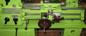
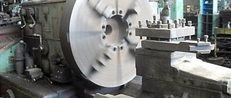
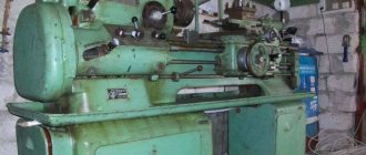
General view of the TVSh-3 screw-cutting lathe
Photo of a screw-cutting lathe TVSH-3
Photo of a screw-cutting lathe TVSH-3
Photo of a screw-cutting lathe TVSH-3
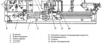
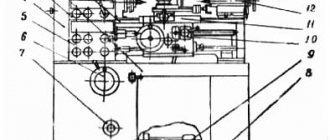
Location of components and controls of the TVSh-3 screw-cutting lathe
Location of controls for a screw-cutting lathe TVSH-3
Specification of components and controls of the TVSh-3 screw-cutting lathe
- power switch
- handle for setting the feed rate or thread pitch
- handle for turning on the lead screw or lead shaft
- handle for changing the direction of rotation of the lead screw or shaft (bit handle)
- handles for setting spindle speeds (A and B)
- handles for setting spindle speeds (A and B)
- rack and pinion lever
- tool holder fixing handle
- caliper cross feed handle
- caliper longitudinal feed handle
- tailstock quill fastening handle
- tailstock quill movement flywheel
- master nut activation handle
- handle for turning on the mechanical feed of the carriage
- flywheel for manual carriage movement
Main design features
A universal screw-cutting lathe consists of main structural units, which are standard elements. These include:
- caliper;
- bed;
- thrust and spindle headstock;
- electrical equipment;
- drive shaft;
- guitar gears;
- a box that provides selection and change of feeds;
- lead screw - it is this detail that distinguishes a screw-cutting lathe from a standard lathe.
Depending on some features, the accuracy of the machine may vary. Therefore, universal equipment can be of both accuracy class N and increased – P.
Front and rear stock
The headstock or spindle has the main role of fixing the workpiece in processing and transmitting rotation to the workpiece from the electric motor.
The spindle is located inside the body of the headstock. A speed control handle is mounted on the outside of the machine body. The tailstock or thrust is necessary to fix the workpiece.
Caliper
The support is designed to move the tool holder with the cutter in the longitudinal, transverse direction relative to the axis of the machine. The lower part of the support is called the slide or carriage.
After a certain time of operation of the machine, the support will need to be adjusted, since otherwise the processing speed will decrease. Adjustment for gaps consists of tightening the wedge strip.
Compared to other parts, the caliper is large. The choice of tool holder is determined by the class of the machine. For large equipment, be sure to secure the cutters with an additional four screws.
Gearbox
This is the main part of the spindle drive. It transmits engine energy to the rest of the machine. Another function is to change the spindle speed and the operating speed of the entire machine.
The box is built into the spindle head housing or in a separate housing block. The speed can be changed in a stepless or stepwise manner. The standard gearbox includes the following components:
- gear system;
- V-belt transmission;
- reversible electric motor;
- electromagnetic clutch with braking system;
- handle for changing gears.
The gearbox operates using gears.
Spindle
This is the main part of the machine, which is made in the form of a shaft with a conical hole for securing workpieces. To ensure that the part has high strength and durability, it is made of high-strength steel.
In the classic version, the spindle is made on high-precision rolling bearings. A special ring is installed on the support of the part, which ensures the accuracy of the machine.
There is a conical hole at the end of the structure. The spindle needs a cavity to install a rod that helps, if necessary, knock the center out of the seat.
The strength and durability of the spindle directly depends on the bearings available there.
bed
This is the main part of the machine, which is made using cast iron. All the most important parts and elements of this design are attached to it.
The frame itself consists of two steel beams. The beams, in turn, are connected to each other by stiffening ribs. Each beam has a connection to two guides.
The guides on both sides belong to the prismatic group. The flat-shaped guide is located inside on the left side.
Threading
There are several ways to cut threads using a screw-cutting lathe. For this, a die, tap, cutter and other types of tools are used.
With their help it is possible to cut internal and external threads
When using a cutter, it is important to fully comply with the technology. It includes:
- correct sharpening of the cutter;
- accurate adjustment of machine operating modes;
- using a template, correct installation of the cutter in the center of the part;
- measuring the resulting dimensions using gauges or templates.
In such work, defects in the form of sharp points, torn threads, scuffing and crushing are unacceptable.
Electrical control unit
The standard control unit for a screw-cutting lathe includes several handles and buttons:
- handle for setting the number of revolutions;
- control system for setting cutting surface parameters;
- handles for caliper control.
A CNC machine has a more complex structure, but can work without operator participation at intermediate stages.
Apron
In the apron of a screw-cutting lathe there are mechanisms that convert the rotational movement of the lead screw and the lead shaft into the translational movement of the caliper.
Kinematic diagram of the TVSh-3 screw-cutting lathe
Kinematic diagram of a screw-cutting lathe TVSH-3
Kinematic diagram. The cutter is moved through a gear system manually or mechanically—self-propelled.
The machine is driven by a three-phase electric motor with a power of 0.6 kW and a speed of 1440 rpm.
The tension of the transmission belts is carried out by a special device that allows you to move the electric motor using special bolts.
Starting and stopping the manufacturing machine using a push-button switch.
Design of the TVSh-3 screw-cutting lathe
A screw-cutting lathe consists of the following main components: front stand, rear stand, bed, headstock, feed box, gear mechanism (guitar), apron, caliper, tailstock, protective casing, trough, electrical equipment, protective screen.
Machine bed
The bed serves to support, secure and interconnect all components of the machine.
The machine bed is box-shaped with windows. Has two prismatic guides.
The front guide is used to move the carriage, the rear guide is used to move the tailstock.
A lead screw and rack are installed on the front side of the frame
The bed is installed on two pedestals.
Headstock of screw-cutting lathe TVSh-3
Headstock of screw-cutting lathe TVSH-3
The headstock serves to support the workpiece and impart rotational motion to it. In a TVSh-3 type machine, the headstock is the gearbox.
From an individual electric motor, through a V-belt transmission, rotation is transmitted to a pulley sitting on the gearbox shaft.
Inside the box, movement is transmitted through shaft 2 and gear 3, which sits motionless on the shaft; onto shaft 4, on which three fixed gears 5, 23 and 6 are located. The latter is involved only in the operation of the bit. On shaft 7 there is a block of gears 8, 9 and 10 and a block of gears 11 and 12, which move on the shaft along a key using handles A and B (Fig. 1). The triple block of gears 8, 9 and 10 has the ability to be in constant mesh with one of the gears of block 5 and thereby transmit movement to the shaft. Through the block of gears // and 12, the movement is transmitted to the stationary block of gears 13, located directly on the spindle of the machine 14. The spindle transmits the rotation of the workpiece using a three-jaw chuck or a faceplate with a driver • which is screwed onto its threaded part. When machining parts on centers, a center is inserted into the spindle.
In addition, a device is mounted in the gearbox that allows you to change the direction of rotation of the lead screw and the lead shaft, i.e., change the direction of movement of the caliper. This is done by moving gear 15 to the left or right extreme position using handle 4 (Fig. 1).
In the left extreme position of the handle, gear 15 will receive direct rotation directly from the gear block 16 located on the spindle. When the handle is in the extreme right position, gear 15 will receive reverse rotation due to engagement with idler gear 16, which in turn receives rotation from the second stage of gear block 16.
The rotation of shaft 17 is transmitted to gear 18, which is in constant engagement with the gears of the transmission mechanism and then with the feedbox mechanism.
With the handle and gear 15 in the middle neutral position, rotation from the spindle will not be transmitted to the feed box, i.e. neither the lead screw nor the lead roller will rotate.
The entire system of gears and shafts is placed in a hollow box cast from cast iron; the box is closed on top with a lid, which is attached to it with four screws. The spindle rotates in two angular contact bearings 19 and 20. The shafts are supported by bronze plain bearings. To adjust the tension of the spindle, two round nuts 21 are screwed onto the back of it.
The gear blocks are fixed in the desired position by rigidly installing the shift handles in the slots on the box. For ease of use, there is a table on the front wall of the box indicating the number of revolutions per minute depending on the position of the handles and an indicator for caliper movement.
There is an oil drain plug 22 on the back wall of the box. The gearbox is mounted on the machine frame with four bolts.
The gearbox mechanism allows you to obtain six spindle rotation speeds and right and left movement of the caliper, and therefore - cut right and left threads.
Transmission mechanism (guitar) of the TVSh-3 screw-cutting lathe
Transmission mechanism (guitar) of a screw-cutting lathe TVSH-3
The transmission mechanism is used to transmit rotation from the gearbox spindle to the feedbox. By changing the gears of the transmission mechanism, you can change the amount of caliper feed per spindle revolution, as well as the pitch of the threads being cut.
The mechanism consists of a bracket 1 with a gear 3 (number of teeth 72) and gear 4 (number of teeth 42) mounted on a roller 2. Gear 4 meshes with gear 5 (number of teeth 70), mounted on the feedbox shaft, and gear 3 meshes with gear 18 of the gearbox.
The transmission mechanism is characterized by a gear ratio; for a TVSh-3 type machine it is
i = 24/60 * 40/64 = 1/4 or i = 24/72 * 42/70 = 1/5
For this machine, this gear ratio is constant, since replacement gears are not included with the machine. For operational safety, the transmission mechanism is covered with a sheet iron casing.
Depending on the production date and manufacturer of the machine, the design of the transmission mechanism may vary.
Feed box of a screw-cutting lathe TVSh-3. Early version
Feed box of a TVSh-3 lathe. Early version
The feed box (Fig. 5) receives movement from the gearbox through the gears of the transmission mechanism. The feed box mechanism makes it possible to obtain metric threads with a pitch of 0.6; 0.8 and 1.0 mm and longitudinal feed of the Caliper within 0.04; 0.05; 0.06 per spindle revolution.
Roller 3 receives rotation from the gears of the transmission mechanism. Three gears 4, 5 and 6 with a number of teeth of 24, 32 and 40 are rigidly mounted on this roller. Roller 1 has a long keyway in which key 12 slides together with gear 13 (number of teeth 32) located in lever 2. Lever carries a roller 11 on which gear 15 rotates freely, which is constantly in mesh with gear 13. Using lever 2, gear 13 together with gear 15 can be moved along the roller and engaged alternately with gears 4, 5 and 6. In each of these positions the lever is held by a pin 16, which fits into one of the holes in the cover of the feed box 14. On the roller 1, a gear 18 is fixed rigidly in relation to the roller, which is constantly in mesh with the block gear 7, mounted on the roller 10. This gear can move along the roller with using lever 8 to the right and left. In the left position, gear 7 meshes with gear 17, which is mounted on the drive shaft. Consequently, in the left position of the gear (right position of lever 5 according to the list of control handles), rotation is transmitted to the roller. When the lever moves to the left, gear 7, moving to the right, disengages from gear 11 and its end protrusions engage with ratchet clutch 9. Thus, when the lever is in the left position, rotation is transmitted to the lead screw. The feedbox mechanism is housed in a housing that has holes for filling oil. The holes are closed with plugs. The feed box is closed on the front side with a cover 14 and secured to the frame with four screws.
Feed box of a screw-cutting lathe TVSh-3. Later version
Feed box of a TVSh-3 lathe. Later version
Support for screw-cutting lathe TVSh-3
Support for screw-cutting lathe TVSH-3
The support (Fig. 6) is designed to move and secure the cutter, which must be in various positions determined by the shape and size of the workpiece.
The support has four carriages: the lower carriage moves in the longitudinal direction along the guide frames both by mechanical drive and by hand. Movement is carried out by an apron attached to the lower carriage. Carriage 2 moves along the guides of the lower carriage and is used for transverse movement of the cutter by hand. The carriage, which carries a tetrahedral cutting head, has only longitudinal movement along the guides of the middle rotary part of the caliper, which can rotate 90° in one direction or another.
The transverse movement of the carriage 2 along the guides of the lower carriage 1 is carried out by a screw 13 and a nut 12. The screw 13 is rotated by hand with a handle 16. Since the screw 13 is installed in supports on the lower carriage, and the nut 12 is fixed on the carriage 2, when the screw rotates, the nut will move and drag carriage 2 along with it.
At the top, carriage 2 has a recess; where the protrusion of the rotating part of the caliper 5 enters. To secure the rotating part there are 2 bolts, the heads of which fit into the circular groove of the carriage 2.
The upper carriage 4 of the caliper can be moved along the guides manually, using the handle 11, which rotates the screw 10 and nut 9.
The guides and the surfaces of the carriages in contact with them wear out so much from prolonged operation that an unacceptably large gap may appear between them.
As a result, the cutter will vibrate and the accuracy of the machine will decrease. To eliminate vibration, the caliper is equipped with adjustable bars 14 and 15, which can be tightened with screws. The tool holder is secured with bolt 8 and tightened by handle 7. When the handle is unscrewed, the tool holder is pressed upward from the upper carriage by spring 6. The tool holder allows up to four cutters to be secured in it simultaneously. The cutters are fastened with bolts 5.
Apron of screw-cutting lathe TVSh-3
Apron of screw-cutting lathe TVSH-3
Using the apron (Fig. 7), you can carry out longitudinal feed of the caliper, mechanical or manual, with a roller and longitudinal feed, mechanical, with a lead screw.
Manual feed by the running roller is carried out by rotation of the flywheel 1, mounted on shaft 2, on which there is gear 4, which meshes with gear 3, sitting at the end of the rack and pinion shaft. The latter engages with a gear rack rigidly attached to the frame. Mechanical feed is carried out by a worm 7, sitting on a sliding key on the running roller. The worm drives the worm gear, and then through the gear system the movement is transmitted to the rack and pinion gear. To turn on the mechanical feed, you must turn handle 9 clockwise. At the same time, the friction clutch mounted in the worm gear is activated. Mechanical feeding by the lead screw is carried out by turning the handle 8, which connects the split nut 5 with the lead screw 6. It is recommended that the rack and pinion gear, when working with the lead screw, be disengaged from the rack by moving the handle towards you. With mechanical and manual feed by a running roller, the rack and pinion gear must be engaged with the rack by moving the handle “pull away”.
Tailstock of screw-cutting lathe TVSh-3
Tailstock of screw-cutting lathe TVSH-3
The tailstock (Fig. serves to support the second end of the workpiece. The body 7 is located on the base 2, which moves along the guides of the machine bed.
A quill 8 moves longitudinally in the body. One end of the quill has a conical hole (Morse taper No. 2), into which, depending on the work being performed, the tail part of the chuck for clamping drills and other tools can be inserted into the center. The quill is moved by the flywheel 11, which rotates the screw 13. For ease of rotation, a handle 12 is attached to the flywheel. To prevent the quill from turning when the flywheel rotates, it has a keyway into which the key screw 10 fits. Handle 9 is used to clamp the quill in the headstock body. The axes of the spindle and tailstock must coincide; To install the quill along the spindle axis, use screw 3 and nut 4. Using them, you can move the body relative to the base in the transverse direction along the base prism for turning long cones. To turn the centers of parts of different lengths, the base is moved along with the tailstock body along the machine bed and secured in the desired position with bolt 5, nut 6 and fusible 1.
Unit design
The TVSh 3 screw-cutting lathe consists of the following elements:
- beds;
- electrical equipment;
- feed boxes;
- protective casing;
- two grandmothers;
- apron;
- calipers;
- cabinet;
- transfer device;
- protective screen.
The frame secures and connects all other elements of the device. It is a box equipped with windows. It consists of two guides. The front guide moves the carriage, the rear guide moves the tailstock.
The bed is fixed on two pedestals. At the front of the device there is a lead screw with a rack.
In TVSh 3, the headstock performs the functions of a gearbox. Its purpose is to support the workpiece and impart rotational motion to it. An electric motor, through a V-belt transmission, imparts rotation to a pulley, which is located on the gearbox shaft.
The transmission mechanism of the electric unit consists of the following parts:
- bracket;
- roller;
- gears
One of the gears meshes with the feed roller gear, and the other with the headstock gear. Rotation is transmitted from the gearbox spindle to the feedbox. When changing the gears of the machine transmission device, you can change the thread pitch.
The feed box of the device receives movement from the headstock through the gears of the transmission device. The feed box allows you to make metric threads with pitches of 0.6, 0.8, 1 mm.
The remaining devices of the electrical unit are designed:
- support - for moving and fixing the cutter;
- apron - for longitudinal support feed;
- tailstock - for fixing the opposite end of the workpiece.
Main technical characteristics of the TVSh-3 machine
| Parameter name | TV-4 | TVSh-3 |
| Basic machine parameters | ||
| Accuracy class | N | |
| The largest diameter of the workpiece above the bed, mm | 200 | 200 |
| The largest diameter of the workpiece above the support, mm | 125 | |
| Height of centers above flat bed guides, mm | 108 | 100 |
| Maximum length of the workpiece at centers (RMC), mm | 350 | 350 |
| Maximum turning length, mm | 300 | 350 |
| Maximum height of the cutter holder, mm | 10 x 12 | |
| Height from the cutting surface to the center line, mm | 12 | 14 |
| The greatest distance from the axis of the centers to the edge of the tool holder, mm | 78 | 90 |
| Spindle | ||
| Diameter of through hole in spindle, mm | 16 | 15 |
| Maximum rod diameter, mm | 15 | 14 |
| Morse taper spindle | №2 | №2 |
| Number of speed steps for direct spindle rotation | 6 | 6 |
| Spindle direct rotation frequency, rpm | 120, 160, 230, 375, 500, 710 | |
| Spindle braking | No | No |
| Handle lock | No | No |
| Reversal | No | |
| Caliper. Submissions | ||
| Maximum longitudinal movement of the caliper, mm | 300 | 350 |
| Longitudinal movement of the caliper by one dial division, mm | 0,5 | No |
| Maximum lateral movement of the caliper, mm | 100 | |
| Transverse movement of the caliper by one division of the dial, mm | 0,025 | |
| Maximum movement of the cutting slide, mm | 50 | |
| Movement of the cutting slide by one division of the dial, mm | 0,025 | 0,025 |
| Angle of rotation of the cutting slide, degrees | ±45° | ±45° |
| Number of stages of longitudinal feed of the caliper | 3 | 3 |
| Limits of longitudinal working feeds of the caliper, mm/rev | 0,08; 0,1; 0,12 | 0,04; 0,05; 0,06 |
| Limits of working cross feeds of the caliper, mm/rev | No | No |
| Number of metric threads to be cut | 3 | 3 |
| Limits of pitches of cut metric threads, mm | 0,8; 1,0; 1,25 | 0,6; 0,8; 1,0 |
| Limits of pitches of cut inch threads | No | No |
| Limits of pitches of cut modular threads | No | No |
| Limits of pitches of cut pitch threads | No | No |
| Tailstock | ||
| Morse taper tailstock | №2 | №2 |
| Maximum movement of the quill, mm | 65 | 65 |
| Maximum lateral displacement of the headstock, mm | ±5 | ±7 |
| The presence of a dial or ruler | 0,025 | No |
| Electrical equipment | ||
| Main drive electric motor, kW | 1,0 | 0,6 |
| Dimensions and weight of the machine | ||
| Machine dimensions (length width height), mm | 1440 x 470 x 1020 | 1100 x 400 x 1150 |
| Machine weight, kg | 280 | 180 |
Scope and functionality
The TV 3 device is a fairly simple piece of equipment. With its help, future specialists learn the intricacies of turning. The risk of injury at work is minimal, since all parts of the mechanism are reliably protected. To ensure greater safety, the lathe is equipped with sheet steel guards. The low rotation speed, when compared with professional equipment in factories, makes it possible to thoroughly understand the intricacies of the device’s functioning.
The main area of application of a lathe is training future specialists. The equipment is installed in workshops that produce specialists with a polytechnic orientation. A universal school screw-cutting machine is used for simple turning operations, including cold metal processing.
The functionality of the school TV 3 lathe is optimal for exploring the capabilities of this equipment, as well as performing semi-professional processing. Kinds:
- drilling blind and through holes in the material;
- boring, turning of surfaces of various types (cones, cylinders);
- cutting off the required part of the material;
- cutting circular elements;
- thread cutting using dies, taps;
- trimming the ends of the processed product.
The TV 3 school lathe shows the degree of accuracy in the mechanical processing of parts. This makes it the best option for carrying out work if the personnel do not have the required level of qualifications.