19.03.2020
- Purpose
- Design
- Operating principle of a modern CNC lathe
- Types of CNC Lathes
- Classification
- Marking
- Hardware programming
- How to choose CNC lathes
- Video
Numerical control caused a revolution in metalworking technology. If on the old equipment the main importance was the skill of the turner, now any operator can stand at the unit, his task is only to monitor the actions of the machine. In this article we will tell you about working on a desktop mini CNC lathe with metal drawings and about its technical characteristics.
Purpose
The material is processed using tools made of durable and sharp tool steel. This mechanical action makes it possible to cut a steel cylinder (ball, cone), remove the top layer from it, and also make a through or blind hole.
There are six main tasks that are implemented by the turning method:
- surface grinding – chips are removed from the outside of the part;
- boring from the inside - it is possible to enlarge the internal cavity or perform operations to give the desired shape;
- trimming the end part - a cut, the edge of the workpiece is processed;
- applying grooves or threads;
- drilling holes using a drill or tap;
- sawing a cylindrical steel rod, pipe.
These are standard features of a classic style CNC lathe. But there are universal models that also include milling tools. Accordingly, they can also be used for milling work.
Using the equipment you can work with the following parts:
- bushings;
- shafts;
- balls, for example, for bearings.
Numerical control also makes it possible to manufacture products of complex configurations. Usually this is not large-scale production, but individual orders according to pre-prepared drawings.
What metal operations can be performed
Thanks to the fact that the human factor has been reduced to a minimum, metal operations have become much easier and result in less waste. It turns out this way because of the program that is embedded in the computer.
It is a kind of template by which the computer understands whether the part is ready or not. This section will talk about the operations that a CNC machine can perform on metal.
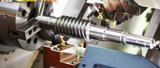
External and internal turning of parts
Everything is simple here, at least for the car. The installed workpiece, which in the future will become a part, is fixed on the machine. It can be secured manually or, if the appropriate equipment is installed automatically (most often the automatic option is used).
Afterwards, external turning of the part begins using either a laser or a blade that is installed on the machine. Gradually cutting off the excess, the workpiece takes the shape of the desired part. This is how external turning of parts is done on a CNC machine.
With the internal everything is about the same, only with changes. After installing the workpiece, the machine begins to drill, or as it is called differently, drill a hole at the base of the workpiece.
Once the hole is ready, the computer will compare it with the template that is written in the given program. If there are any flaws, he will analyze whether it can be corrected (as a rule, yes, because machines rarely make mistakes). Afterwards the workpiece is polished and the part is ready.
Longitudinal processing of the workpiece
Longitudinal processing is a method that is used for the manufacture of strips, strips, tapes. Depending on the program that is installed on the computer.
Such work on a CNC machine is carried out mainly using a laser, as this allows you to get rid of defects and speeds up the work process. After installing the workpiece, the numerical control on the machine will process it in accordance with the specified algorithm of actions. The laser portal is driven by stepper motors on which it is mounted.
Roughing and finishing
To begin with, what is this anyway? Roughing of metal consists of adjusting the part to the desired size by removing layers of metal.
Typically, in a CNC machine, this role is performed by the computer after the part has already been cut. Finishing comes next and consists of polishing the surface of the product. The machine performs all this according to given algorithms.
Adjusting the length of parts
The program that is given to the computer clearly states the dimensions of the part. The blanks are also given in suitable sizes. Before inserting a part, the machine adjusts and sets itself up for production.
After that, he begins to do the work, after which he compares the size with those given by the person. If there are no deviations, the part is ready. If there is, the CNC machine begins to grind the part, removing layers of metal and adjusting the length.
Making grooves, recesses and holes
Grooves and recesses are holes that are made into a part. Such holes can serve either to allow another part to fit into them, or for installation to some device. A CNC machine makes such holes using a laser, making high-precision cuts.
They can be rectangular, T-shaped, dovetail, shaped, through, open, closed and others. What shape the hole will be depends on the part and the program that the person has installed in the numerical control.
Inch and metric thread cutting
Almost everyone has seen this type of carving. It is used mainly so that one part can be screwed to another. The main parameters in the manufacture of such threads are pitch and size. In this case, a step means:
- outer diameter, measured between the top points of the threaded ridges located on opposite sides of the pipe;
- internal diameter as a value characterizing the distance from one lowest point of the cavity between the threaded ridges to another, also located on opposite sides of the pipe.
All parameters need to be entered into the machine’s computer, after which it will cut out an excellent and even thread using a laser.
Reference! In any case, the parameters for making threads on a product are entered by a person into the computer of the machine, and the latter, acting according to an algorithm, uses a laser to make an excellent thread.
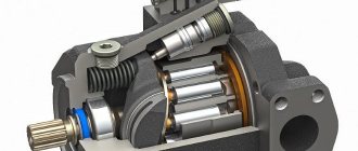
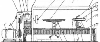
Design
Regardless of the type of model, its basic elements remain the same:
- Bed. In simple words, this is a strong and reliable table that can withstand large masses and vibrations, but at the same time remains motionless and convenient for use. For heavy weight products, it is recommended to mount the legs on a concrete base.
- Grandma. This is a node that can be called a work area. He is responsible for maintaining and moving manufactured products. There are two of them - front and rear. The first contains the engine (underneath), the gear switch and the spindle - it is responsible for rotation. In the second - only fixing elements.
- A caliper is a moving part responsible for moving the cutter in several planes. There are also strong clamps installed here that allow you to fix the tool.
The auxiliary devices include the control panel itself. Its task is to program CNC lathes; on different models, working with it differs in detail, but the essence remains the same. With its help, tasks are distributed to all moving components of the equipment, that is, to the rotating spindles (speed, direction) and to the support. The built-in computerized device independently selects the sequence of actions, the maximum possible speed of metal processing and controls the process.
Another auxiliary system is coolant. This is the supply of cutting fluid to the working area, as well as the removal of metal shavings generated during work.
With such machines a high degree of automation can be achieved. The operator's actions are actually optional.
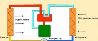
Operating principle of a modern CNC lathe
Most operations are performed automatically. All of them are divided into main ones, which are responsible for metalworking, auxiliary ones - chip removal, lubricant supply, installation and removal of parts.
The work algorithm is as follows:
- Fixing the workpiece.
- Decree on equipment, that is, additional means for securing cutting elements.
- Installation in the tool holder.
- Turning on the drive. The metal structure begins to rotate.
- Place the cutter at the starting point - at a distance from the metal.
- Passage - the top layer is removed, followed by retraction of the blade.
- Alternating stages 5 and 6. In this case, positioning occurs in different planes, for longitudinal and transverse movement.
- Control measurement of part parameters.
- Removal from machine equipment.
In fact, everything is done automatically, except for installing and removing the element. Even dimensional measurement is often automated, and fixing devices have quick-release fittings and other features to simplify the operator’s work.
In general, the use and adjustment of a CNC lathe (screw-cutting lathe) leads to a reduction in labor costs, a reduction in the number of defects, and an acceleration of the process. Production with such devices is much more efficient. The number of injuries sustained at the plant also decreases. It becomes possible to produce complex metal parts without much difficulty.
sells installations with a numerical control panel at an affordable price. The company offers additional services - delivery and setup of new equipment. In the catalog of their online store you can find many high-quality models of different price segments.
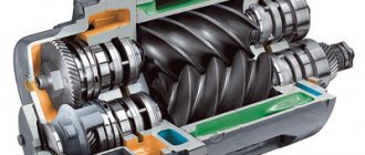
Construction of CNC machines. Main parts and support systems for CNC machines
The entire design of a CNC machine (CNC machining center) intended for processing facades of MDF or other wood materials (wood, chipboard, HDF, etc.) consists of various components, mechanisms and assemblies, the task of which is to perform a specific function assigned to them. Depending on the modification of the CNC machine, it is possible to have additional components and assemblies that provide a diverse range of parts processing, facilitate the operator’s work and create safe conditions for people, equipment and product blanks.
A CNC machine (machining center) consists of a bed, a group of devices that provide positioning and locking of the workpiece (work table), as well as a main spindle and an operating unit designed for processing the part with milling, drilling, sawing, and grinding tools.
bed
The bed is the supporting structure of a CNC machine. It ensures a rigid and stable position of the machine, as well as the mechanisms, components, assemblies and other equipment located on it. The main design features of a CNC machine bed are strength, resistance to deformation and the ability to absorb vibration.
In the traditional version of a CNC milling and engraving machine, a U-shaped console (portal) is installed on guides fixed to the bed, which, through a gear-rack transmission, moves along the Y axis. In turn, the U-shaped console also has guides, according to with which the spindle platform moves along the X axis. Along the guides of the spindle platform, along the Z axis, as a rule, using a ball screw (ball screw), the main spindle or operating unit of the CNC machine moves. Thus, the operating tool is capable of moving along any coordinate axis X,Y,Z.
CNC machine work table
A work table is a group of parts necessary for positioning and fixing the workpiece being processed. Depending on the design of the CNC machine and the set of options, different typologies of work tables are provided.
For processing MDF facade blanks, the best option would be to select a work table with a method for blocking large and flat parts that can be easily fixed with a vacuum system. Such tables include vacuum lattice tables with a sealing cord, as well as console work tables with a system of vacuum suction cups and clamps.
Matrix (lattice) tables
They are usually made from a special composite material based on phenolic resins and synthetic fibers. They have a monolithic rectangular shape with periodically located holes for supplying vacuum, and grooves (in the form of a lattice), into which special sealing cords are inserted to provide vacuum to the area in the shape and size of the part being fixed.
Typically, the working surface of a CNC machine consists of several matrix work tables separated by T-shaped slots. On the one hand, connecting the optimal number of work tables to the vacuum system ensures the best blocking of the workpiece on the CNC machine; on the other hand, T-shaped grooves allow you to secure the part without using a vacuum, using mechanical clamps (clamps).
Console tables with a system of vacuum suction cups and clamps
CNC machining centers are most often equipped with similar designs. The work table is a transverse movable console located on the frame, equipped with freely positionable and interchangeable suction cups and clamps. It allows you to quickly fix parts of any shape and size and greatly reduce setup time. To fix the workpiece in the coordinate grid of the CNC machine, it is enough to move the movable console and the suction cup on it to the appropriate position. At the same time, by selecting the size of the suction cups and turning them, you can adjust the processing process of the workpiece without causing damage to the fixation devices.
In addition, when it is necessary to lock small parts or parts that cannot be firmly locked using suction cups alone, it is possible to replace the conventional suction cups with the most suitable quick-release clamps.
CNC machine stop system
To quickly and accurately position parts on the work tables of a CNC machine or CNC machining center, different stop systems are used. The standard front and side stop system consists of vertical rods that are used as reference points in the CNC machine's coordinate system. Several side or front stops form a line of stops, which allows you to position the rectangular part exactly at a right angle.
Operational block
An operational unit is a group of operational units and additional devices that provide various types of processing of parts, removal of chips and dust from under a working tool, protection of the operator and equipment from the ejection of cuttings of parts and tool fragments.
CNC milling and engraving machines with a minimum configuration are equipped with a powerful electric spindle with a manual tool change system and an aspiration casing. Options for more expensive machines may include spindles with clamps for quick tool changes during the machining cycle, units for additives and milling of horizontal holes and recesses, as well as rotary units for processing workpieces along 2 or 5 coordinate axes.
CNC machining centers in the arsenal of the operational unit also have a drilling and filler group, which allows making vertical and horizontal holes. Also, a head for a circular saw can be installed on the group block to perform grooving or cutting.
In addition, the operating unit of CNC machines and CNC machining centers can be equipped with an additional chip deflector shield, a measuring probe, a laser projector, a workpiece clamping device and other options.
CNC control unit. Remote Control
The control unit allows you to control the main functions of the machine. Typically, the control unit is mounted on the electrical cabinet of the CNC machine, which houses the spindle inverter, servo controllers and other electrical components of the CNC machine controls, as well as a forced cooling system that allows the electrical components to operate normally, even at elevated temperatures.
Leading manufacturers of CNC machines and CNC machining centers provide for the installation of a PC system unit and a monitor in the electrical cabinet, which makes it possible to create and edit complex control programs directly at the machine.
Portable control panel , designed for manual control of the machine in online mode. In addition to the button panel, it has rotary knobs for regulating the speed of movement of the operating unit and the speed of rotation of the main spindle. This greatly facilitates the operator’s work during setup and calibration of the CNC machine, and also reduces the risk of equipment damage during processing.
CNC tool changers
CNC machines and CNC machining centers equipped with spindles with clamps for quick tool changes are additionally equipped with tool magazines. They contain the tools and assemblies necessary for processing, which are automatically captured and installed in the main spindle of the CNC machine. Tool stores are divided into several types:
- Comb type . It is permanently located on the CNC machine bed. Can contain up to 10-12 instruments.
- Revolving type . As a rule, it is located on the movable console of the operational unit. Has up to 12-16 positions.
- Chain type . This magazine can hold more than 20 tools at a time.
Also, the CNC machine can be equipped with a single bracket for fixing the quick-release chuck, also designed for automatic installation and removal of tools in the main spindle. However, the instrument is inserted and removed from there manually.
CNC machine compressed air system
Compressed air is necessary for the operation of many systems and mechanisms of a CNC machine (CNC machining center), including for the functions:
- Blowing the working tool;
- Raising and lowering stop lines;
- Fixing parts with pneumatic clamps;
- Operation of vacuum supply valves;
- Activation of protective and suction covers;
- Work of the operational unit, including the drilling group;
- Work of tool shops, etc.
To supply compressed air of the required quality, a pneumatic unit is used, which regulates the pressure in the machine, cleans it of dust and moisture, and also supplies metered lubricant to the pneumatic system of the CNC machine.
Vacuum system of CNC machine
For the efficient operation of a CNC machine in the production of MDF facades, a vacuum is required. The main task of the vacuum system is to securely fix the workpiece on the CNC machine table, including using suction cups and clamps.
Despite the variety of types of vacuum pumps, oil-free rotary vane pumps have gained the most popularity in the woodworking industry. They are distinguished by high productivity, reliable continuous operation during the shift, and a long service life.
Security devices. CNC machine alarm systems
Safety devices and alarm systems are designed to protect the health of the operating personnel of the CNC machine, trouble-free operation of the equipment, and also protect the workpieces from damage. There are three main safety systems on CNC machines and machining centers:
- Active safety system . This should include:
- Emergency stop buttons;
- Emergency rope;
- Contact mat;
- Photo relay.
- Passive safety system:
- Protective fences of the working area;
- Security doors;
- Protective covers for the operating unit and main spindle;
- Machine covers and inspection windows.
- Software protection , including:
- Software protection;
- Protection against failures in other supply systems (electricity, air, vacuum);
- Protection against operator errors.
Alarm systems include special safety signs attached to the machine in hazardous areas.
Additional options for CNC machines and machining centers
- Sensor for measuring and calibrating tool length. Automatically searches for the zero point of the worktable surface along the Z axis and calculates the tool length.
- Laser projector. Helps position the workpiece or suction cups along projected lines or crosshairs.
- Barcode Scanner. Searches for the required program in the computer memory using the read barcode.
- Conveyor for removing sawdust, shavings and small scraps.
- Specialized software.
Types of CNC Lathes
Any metalworking equipment with a control panel has one of the components movement systems. Depending on how the tool and workpiece move, three types of devices are distinguished.
Positional
Before each new cycle, the cutting structure is “sent” to a pre-selected position from which it will be most convenient and efficient to start work. The coordinates are determined automatically taking into account the friction force, direction of movement and other factors. In this case, the shortest route is used.
When the cutter is placed in its original place, the speed of movement gradually slows down, this allows for high precision in positioning. If movement is assumed to be along two coordinates, then, depending on the type of automatic CNC lathe, it either occurs alternately or simultaneously - diagonally.
Contour
The second name is continuous. They operate in constant motion of several working units, that is, not only the tool moves, but also the workpiece. The main difference occurs in the number of controlled coordinates - from 2 to 6. The more there are, the faster the process and the wider the possibilities. For example, the presence of two axes allows you to work only with flat surfaces, while the third one adds volume.
All contour systems are divided into:
- straight;
- rectangular;
- curvilinear.
This difference determines the movement of the cutter.
Adaptive or universal CNC lathes
This is a combined mechanism that uses both one and the second system, depending on the specific situation and its needs. Such machines are the most efficient and productive. They have the highest execution speed and accuracy.
Varieties
There are enough varieties of lathes to perform a wide variety of jobs. There are five of them in total:
- horizontal turning-turret;
- tokor-frontal;
- rotary turning;
- multi-spindle;
- turning and milling.
Now we will talk about everyone separately.
Horizontal turning-turret
Designed mainly for mass production of parts. Using a chuck, parts are installed that will process the workpiece before it becomes a part.
Torque-frontal
This machine is used for processing parts whose diameter exceeds the size of the workpiece. These are mainly railway wheels, flywheels and others. It can also remove ends, make cylindrical parts, make grooves, and so on.
Lathe-rotary
Such machines are designed for workpieces that weigh several tons. Also, the workpieces for such a machine have a diameter greater than their height. Thanks to the chuck and the cutting parts installed on it, it is possible to apply threads to the workpiece or drill holes.
Multi-spindle
As the name implies, the design of this machine contains several spindles, which ensure processing of the workpiece to the state of the part in several places, either simultaneously or in shifts after every certain period of time.
Turning and milling
Turning and milling machines with installed CNC are universal. They can perform a wide variety of work with products. Everything will depend on what program was installed in the numerical control computer and what tools were installed on the chucks.
This machine can perform any functions of highly specialized equipment, be it turning, drilling, milling. He can handle any type of work.
Classification
In addition to the above distribution, there are many more factors by which all devices are divided into models and categories. Let's take a closer look at them.
By spindle placement
In fact, this predetermines the location of the workpiece. There are vertical and horizontal CNC lathes. The first ones are less common, but they are convenient because they take up little space. However, to install them you will need a fairly strong concrete base.
If the part is attached on both sides in a horizontal position, then the bed itself, as well as the working area, takes up more space. This is a more classic and familiar form, since the usual ones, without a control panel, had exactly this arrangement.
According to the location of the guides
This is an important node along which sliders with tools move. They can move in several directions:
- horizontally;
- vertically;
- along an inclined line.
On the organization of the instrumental system
There are two types:
- Replacement magazines with tools. Sometimes one can contain up to 300 varieties of blades.
- Turret spindle heads. The cassette tool holder holds up to 12 cutters.
By type of work performed
All machines differ in technological groups. Turning on CNC machines has the 1st number. While milling, for example, is 6th.
The number of functions may vary. The more capabilities the equipment has, the more versatile it is. Multitasking can be expressed by the ability to make blind and through holes, as well as apply internal and external threads.
CNC Programming Techniques for Current Practices
The movement of the tool/sliders on a CNC machine can be done by the operator using rotary buttons or an electronic handwheel in the same manner as on conventional machines. This method of transferring motion to CNC machines is known as manual control and is not a CNC method.
Diagram of the top-level functional modeling methodology (IDEF0) for machine processing based on STEP-NC: 1 – knowledge base; 2 – production resources; 3 – ISO standards (10303, 14649, 6983); 4 – CAD data (STEP file AP238, APT, G-code); 5 – workpiece; 6 – processed workpiece; 7 – CAD/CAM software; 8 – interface; 9 – operator; 10 – machine tool CNC programming methods can be broadly classified as follows:
- Manual.
- Computer.
- Conversational programming.
- Use of CAD/CAM software.
- Parametric method.
Nowadays, programming of CNC machines is done primarily using commercially available CAD/CAM software, as well as through dialog-based menu-based or function-based programming.
But for the production of simple parts, the manual option (with or without parametric/macro programming) is also the optimal programming option.
Methodology for manual programming of parts processing
Manual part programming is traditionally based on the ISO 6983 (G-code) standard mentioned earlier. If this kind of coding is done and fed directly block by block through the machine console, the process is called manual data entry.
When processing a part manually, the program is completely developed and saved as a file (for example, an MS-Word file or other compatible program), and then submitted to a CNC machine.
Computer programming of parts processing
Machining of parts using a computer for CNC machines is done through various machine languages developed for this purpose. It should be noted: quite a lot of machine languages have been developed, among which “APT” (Automatically Programmed Tool) and “COMPACT II” are common.
Despite the similar approach between APT and COMPACT II, the former language is relatively easy to understand and use. The Automatically Programmed Tool system uses simple English words to instruct the CNC machine to perform various functions.
The process of plasma cutting using an industrial CNC machine allows you to achieve highly accurate results in producing cuts at specific points on the part. Even if we take into account that computer programming of parts is not currently used as such, the APT system remains an important machine language throughout the world. This is due to the fact that a large proportion of CAD / CAM approaches to part processing are based specifically on “APT”.
The APT machine language is also important because many of the concepts included in the language's structure formed the basis for other interactive graphics systems that were subsequently developed.
Step-by-step computer processing procedure on a CNC machine
The following procedure determines the processing of parts using a computer:
- The programmer determines the geometry of the part, cutter movements, feed, speed and other cutting parameters.
- The programmer codes the part geometry, cutter movement, feed, etc., according to the format of the programming language.
- The source is compiled to produce a machine-independent list of torch movements and other machine control information (torch location control data file or CL data file).
- The CL data is then processed by the machine specific post processor to generate machine control data/part program for the specific machine. Post processing includes adding G-codes, M-codes and other machine-dependent information in the required format.
This type of programming is a kind of dialogue between the CNC machine and the operator. This interactive search software systematically searches for all relevant information about the jobs being performed on a CNC machine directly through the operator.
Based on the information received, a part processing program is developed. Information provided by the operator to the software through a dialog form:
- workpiece size,
- workpiece material,
- type and sequence of operations performed,
- final task parameters, etc.
With the interactive method, the program is created directly on an industrial CNC machine. Program creation is accompanied by the use of graphical and menu-driven functions with macros - simple part processing programs available in the controller memory.
The programmer will be able to visually check the correctness of various inputs when creating a program. When a procedure is completed, most interactive controls show the programmer a graph of the process path occurring at points in the processing cycle.
This is the simplest way to develop a part program and is widely used in industry. However, this type of code injection is limited to the production of components or jobs with relatively simple part geometries.
Conversational programming software is usually provided by the machine manufacturer according to the machine's capabilities.
Programming via CAD/CAM software
This type of programming is performed using commercially available CAD/CAM software designed for use with a variety of industrial CNC machines.
Some manufacturers provide their own versions of CAD/CAM software, but here the applicability is usually limited to the specific machine. CAD/CAM software usually comes bundled with drafting (drawing) tools.
Tools are also provided to create a part program from a drawing of the job being performed. A drawing of the work being carried out can be presented directly in 2D or 3D format using the drawing tools of CAD/CAM software.
Drawings may be provided in a compatible format supported by the software. Once the software drawing is ready to be run by the software, some relevant information is searched in a similar manner to the dialog form software.
If relevant information is found, CAD/CAM programs are capable of generating part procedures for a specific machine type. Meanwhile, CAD/CAM software generates part programs only for machines or controllers that are registered in the software's database.
In terms of usefulness, the difference between conversational programming software and CAD/CAM software is the degree of versatility. CAD/CAM software appears to be more versatile, equipped with more sophisticated tools, compared to conversational programming software.
CAD/CAM packages have been developed that provide CNC code generation capabilities:
- MasterCAM,
- CATIA
- Pro/ENGINEER,
- Pro/Toolmaker
- Siemens NX,
- DELCAM
- EdgeCAM
- Work N.C.
- GibbsCAM and others.
The procedure for generating codes for producing components on a CNC machine varies from one CAD/CAM software to another CAD/CAM software. However, in this case, three main stages are performed in almost any variation:
- The programmer provides some general information.
- The geometry of the workpiece is defined and cut according to the shape of the workpiece.
- Processing operations are defined.
Marking
Each device has a designation consisting of numbers and letters. It can be applied with paint, but more often it is engraved. Using this set of symbols you can find out detailed information about the technical characteristics of the product. All devices are marked according to the same type, so lathes differ mainly in the first number.
What do the numbers mean:
- The first is a group (by type of activity, that is, milling, drilling or other purpose).
- The second is a subtype. This is a more specific description of technical characteristics, for example, level of automation, direction of movement, etc.
- The third and fourth are additional features.
The letter is not always assigned and not everywhere. Its presence indicates the modernization of the standard device of a CNC lathe. For example, at the very end there is an accuracy class. This may be the following letter designation:
- N – normal.
- B – high.
- C – especially accurate.
There may also be an indication of the type of control panel. For example, the letter “C” denotes digital modification.
Sometimes you can see abbreviations of the most popular factories, for example, MS – this is Moscow Grinding.
We will provide information in the form of an image to clearly show the location of all signs:
Programming turning equipment
Working with such a mechanism is the work of a well-coordinated team. Initially, when modeling a product, a technical order is received. Engineers create a drawing. Design takes place on a computer using special systems - CAD, since all schemes, when saved, must be saved in a specific format - STL. Such files store information about three-dimensional models.
From this CNC lathe program, the document is then transferred to the equipment memory. A set of actions is formed that will most quickly and efficiently help complete the product in the drawing.
The operator only monitors the process and can intervene in the actions of the control controller and make adjustments.
Computer programs for computer-aided design are not always required at the programming stage. Sometimes all parameters can be entered manually directly on the display. This is relevant when in the process of work you need to achieve the simplest possible forms.
In general, the CNC system itself consists of:
- The remote control is a cabinet with buttons that the operator presses;
- display – program actions will be displayed on it;
- management controller - intended to distribute responsibilities between all nodes;
- random access memory - a feature of such equipment is that several programs can be stored in its memory, and then quickly switched and reprogrammed everything to a new cycle.
Features of machine programming
Unlike a computer, where a new and empty area of memory is allocated for each program and variable, everything is different in machine tools. The fact is that the program at the time of launch does not know what position the cutters are in, whether the guides are secured, and so on. If you simply run the program without preparation, the CNC, for example, can move the cutter even further to the left, which is already in the very left position, and then the drive or the cutter mount may break.
To prevent this from happening, before each launch, zeroing and initialization commands are built into the program so that each element is returned to its original position. This is better than just checking what is where - after zeroing, we will know for sure that all elements of the machine are in a position known to us and the program will be able to work with them correctly.
It is also important to understand that machines work with living material: metal, wood, acrylic, stone, etc. The material is imperfect, may have internal defects, and may melt and crack. Cutters and spindles are also made of some materials that have thresholds for heating, strength and speed. If you make a mistake in the computer code and cause a memory overflow, the computer will simply freeze. You reboot it, and that's it. And the machine can break the cutter or damage the spindle. And this farm is worth it, be healthy.
How to choose CNC lathes
Before you buy equipment, you need to make sure you need it. We recommend installing a rather expensive tool for the following purposes:
- In a small enterprise, when each product is made individually and has complex geometry. Usually in such cases the drawing is written out in detail, so it’s easier to immediately use a good program and place the layout in the control panel.
- In mass production to save time and human resources. Only an automated machine can provide you with a fast and virtually continuous production process.
- In the case of the manufacture of small parts requiring high quality precision. Making very small metal parts by hand is a very meticulous and thankless job. Only such equipment will help achieve amazing accuracy.
So we briefly covered the question of when you need to buy a machine. Now let's decide how to choose it.
It is clear that the more additional functions, the more expensive the device. But it's important to understand in advance whether you need this multitasking. If your workshop already has screw cutters and drilling equipment, then the turner is not required to perform these functions at his workplace.
But if you have a small, small-scale production, then purchasing universal and multifunctional equipment is often a profitable solution.
High quality and affordable price are the characteristics of the Sarmat online store. Here you can find a wide range of products. Consultants will help you with your choice, and company employees provide additional services as an adjuster of CNC lathes. Also, after the purchase, the company itself will deal with the issue of transportation and loading. Visit the catalog on the official website to find a suitable model at a reasonable price.