Information about the manufacturer of the woodworking milling machine FSSH-1A
The manufacturer of the FSSH-1A(K) milling woodworking machine is the Kirov Machine Tool Plant , founded in 1880. The main specialization of the plant is the production of machines for sharpening and preparing wood-cutting tools for work.
Another manufacturer of milling woodworking FSSh-1A is the Kurgan Woodworking Machine Plant , which produces equipment for furniture and construction and carpentry industries.
The manufacturer of the milling machine FS-1, FSSh-1, FSSh-1A(D) is also the Dnepropetrovsk Machine Tool Plant DSPO currently LLC Stankostroitel.
In the USSR, the Dnepropetrovsk Machine Tool Plant specialized in milling group machines throughout its existence. However, in May 1999, this largest production of machine tools in Ukraine was restructured, and as a result, six independent enterprises appeared, one of which is Stankostroitel LLC.
Machine tools produced by the Kirov Machine Tool Plant, KSZ
- KPA-50
- round rod machine. Outlet diameter of parts Ø 20; 25; thirty; 35; 40; 45; 50 - SR-4
- thickness planer - TCPA-7
- sharpening machine for circular, frame and band saws - FSSH-1A
- milling machine - Ts6-2
- universal circular saw - TsM-120
is a multi-disc machine for sawing two- and three-edged timber (carriage) up to 120 mm high - TsM-150
is a multi-disc machine for sawing two- and three-edged timber (carriage) up to 150 mm high
Analogs
The FSSH-1 machine, the abbreviation of which stands for tenon-cutting milling machine, is produced by several Russian enterprises, which, as a rule, add the first letter of the city where the manufacturer is located to the marking in brackets. The presence of the letter A indicates improvements made in the design. Therefore, machine models are produced:
- FSSH-1A – Kurgan Woodworking Machine Plant;
- FSSH-1A(K) – Kirov Machine Tool Plant;
- FSSH-1A(D) – Dnepropetrovsk LLC “Stankostroitel”.
The exception is the F4 machine model, which is considered an outdated version, produced before the FSS-1 model. It differs in the diameter of the tool used for wood processing (up to 150 mm), the number of spindle revolutions (6 - 8 thousand per minute) and the power of the spindle electric motor (5 kW).
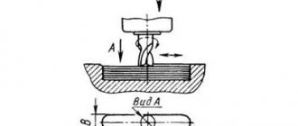
FSSH-1A Woodworking milling machine with tenoning carriage. Purpose, scope
The woodworking milling machine FSSH-1A with a movable tenoning carriage model FSSH-1A is designed for performing a variety of milling work on wood with manual feed, cutting simple tenons up to 100 mm deep using a tenoning carriage, curved milling according to a template with manual feed.
A machine without a tenoning carriage is designated FS-1 .
The FSSH-1A milling machine is designed for performing a variety of milling work on wood along guide lines with manual feed (manufacturing linings, floorboards, plinths, platbands, panels and other molded products), cutting simple tenons using a tenoning carriage and curved milling according to a template with manual feed.
Operating principle and design features of the FSSH-1A machine
The FSSH-1A machine is assembled on a one-piece cast vibration-resistant cast iron frame, inside of which a high-speed spindle unit with a lifting mechanism and a drive from a two-speed electric motor is installed.
A cast iron table with a tenoning carriage is installed on the bed. The upper spindle support, cutter guard with adjustable guide rulers and a pipe for chip evacuation are mounted on the table.
The tenoning carriage has a rotating ruler with an eccentric clamp. Additionally, the machine can be equipped with an automatic feeder (automatic feeder), which is easily mounted on the machine table.
In recent years, with the development of cabinet furniture production, in our country milling machines are mainly used for milling curved chipboard edges. Processing is carried out mainly in two ways.
- The first method: a sanding head with a sanding belt attached to it is installed on the spindle, and the chipboard is simply sanded, i.e. The milling machine turns into a grinding machine.
- The second method: milling using a special cutter with carbide replaceable inserts.
Moreover, for milling you can only use cutters with replaceable inserts, and this is an indispensable condition, because When processing chipboards, carbide plates become dull quite quickly. The reason for this is the fairly high hardness of chipboard and its heterogeneous structure.
The room where the machine is installed must meet the requirements of class P-II according to the PUE.
The machine can be operated in the temperature range from +10 to +35°C, with an average relative air humidity of no more than 80%, in a non-explosive environment, in the absence of direct exposure to precipitation.
Type of climatic modification and category of machine placement - UHL4.2, category of storage conditions - 2 according to GOST 15150-69.
Requirements for workpieces entering the machine.
Workpieces must meet the requirements of GOST8486-86 and GOST2695-83:
- Wood moisture content should not be more than 15%
- the quality of wood blanks is not lower than grade 1
- the deviation of the base face of the workpieces must be at least 0.15 mm over a length of 1000
Milling machine with tenoning carriage FSSH-1A (K)
PURPOSE:
Designed for performing a variety of milling work on wood, cutting simple tenons and lugs using a tenon-cutting carriage, longitudinal milling along guide lines and curved milling using a template.
APPLICATION AREA:
It is used in the production of carpentry, solid wood doors, parts and elements of cabinet furniture, furniture facades and other woodworking enterprises.
PROCESSING SCHEME:
| Longitudinal milling | Milling of tenons and lugs | Curvilinear milling using a template |
DESIGN FEATURES:
| DESKTOP The table is made of cast iron. This ensures stability in operation, as well as wear resistance throughout the entire service life. | |
| CASING The protective cover of the knife shaft allows you to install a tool with a maximum diameter of 250 mm. Made from cast iron. | |
| SPINDLE SUPPORT The shaft is rigidly fixed at the top. Eliminates spindle runout and increases processing accuracy. | |
| Tenoning carriage The massive cast iron carriage, 1000 mm long, allows you to cut tenons and lugs on workpieces. | |
| ECCENTRIC PRESSER Reliably holds the workpiece during tenoning. | |
| SPINDLE ADJUSTMENT The spindle is raised/lowered using a flywheel. | |
| CARRIAGE GUIDES The carriage moves on bearings along cast guides. | |
| RULER GUIDES The guide ruler is adjusted to the removal depth using a millimeter scale. | |
| SPINDLE STOPPER Rigidly locks the shaft when installing the tool. It is located in the engine compartment and is equipped with a limit switch that prevents the machine from turning on when the spindle is locked. | |
| REMOTE CONTROL Conveniently placed at operator eye level. |
ADDITIONAL EQUIPMENT:
| COPYING CARRIAGE FSSH-1A(K) 25.000 Designed for the manufacture of curved elements of windows, doors and furniture on milling machines with a vertical spindle and a tenon-cutting carriage, achieving high productivity and ensuring the safety of the work performed. The device with the workpiece moves relative to the machine spindle (the depth of the curved profile is ensured) on two ball guides, rolling a template with a roller, which is installed (attached) in front to the machine bed. To fix the workpiece on the device table, there are two eccentric clamps. |
| CO-MATIC AUTOSEEDERS. MODELS MX38, MX48 Additionally, the machine can be equipped with an automatic feeder (automatic feeder), which is easily mounted on the machine table. Advantages of installing an automatic feeder:
|
TECHNICAL CHARACTERISTICS OF THE DEVICE
| Maximum transverse stroke, mm | 200 |
| Milling length, mm | Corresponds to the travel of the machine carriage |
| Number of clamps, pcs. | 2 |
| Dimensions, mm | 680 x 295 |
| Machine weight, kg | 60 |
Photo of a machine with a copying device (25th node)
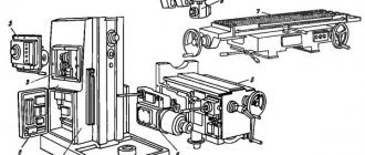
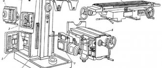
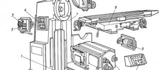
FSSH-1A Location of the components of the milling machine
Location of components of the milling machine FSSH-1A
List of components of the FSSH-1A milling machine:
- Clamp with ruler - FSSH-1A(K)20.000
- Carriage - FSSH-1A(K)40.000
- Bed – FSSH-L.10.000
- Tool guard - FSSH-L.30.000
- Spindle head - FSSH-L.40.000
- Spindle bracket - FSSH-L.50.000
- Tool protection - FSSH-L.60.000
- Lifting mechanism - FSSH-L.70.000
- Electrical equipment - FSSH-L.80.000
FSSH-1A Location of milling machine controls
Location of controls for the FSSH-1A milling machine
List of controls for the FSSH-1A milling machine:
- Ruler fastening handles;
- Handles for securing the tool protection housing;
- Belt tension screw;
- Spindle lock;
- Spindle speed selection switch;
- Input switch, automatic;
- Buttons for fixing the stroke length of the carriage;
- Spindle bracket clamp handle;
- Handwheel for moving the spindle bracket;
- Handwheel for moving tool protection;
- Button for emergency and working shutdown of the machine – “Stop”
- Machine power button – “Start”
- Product clamp handle;
- Button for fixing the stop of the guide ruler;
- Clamp fixation handle with ruler;
- Handwheel for moving the spindle headstock;
- Spindle lock fastening button;
- Spindle headstock clamping handle;
- Ruler bracket fixation button;
- Button for fixing the tool guard;
- Handle for fixing the clamp in height.
Kinematic diagram of the FSSh-1A milling machine
Kinematic diagram of the FSSH-1A milling machine
Movements in the machine:
- The main movement is the rotation of the cutter at two speeds
- Translational movement of the carriage - movement of the workpiece along the cutter (travel 926 mm)
- Raising and lowering the spindle head - installation vertical adjustment of the position of the cutter
- Moving and clamping the spindle bracket - the bracket must hold the free end of the spindle
- Moving the guide ruler - installation movement of the stop of the guide ruler in order to set the milling depth
Description of structural elements
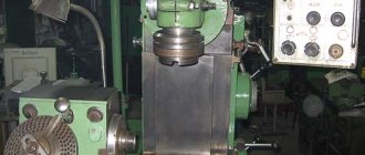
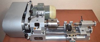
Appearance
Using this machine model, you can perform a wide range of milling operations for processing wooden workpieces. The supply of materials occurs manually, there is the possibility of cutting tenons. For this purpose, the design has a special tenoning carriage. You can also process curved surfaces using templates.
The design of this model is simple, the kinematic drive diagram is not complicated. The basis of the equipment is a cabinet, inside of which the power plant is located. From it comes a rotational movement to the vertical shaft. The FSSH-1A model has an adjustable table, safety equipment and a set of guides for processing wooden workpieces.
Overview of hardware components:
- bed. This is a molded rigid box required to install the main components. Some modifications of the machine involve manufacturing the frame by welding;
- Desktop. It is mounted in the upper part of the frame and is made from cast iron. The surface of the table is carefully polished, additional stiffening ribs are installed in the lower part;
- drive device. Consists of a two-speed electric motor, which is connected to the spindle headstock by a belt drive;
- spindle head. A working spindle is installed on it using rolling bearings. Its shaft has a tapered hole for a mandrel. The cutter is installed using a differential nut;
- tenoning carriage. It is installed on the edge of the desktop. Its movement relative to the working cutter occurs with the help of rolling bearings. The tenon carriage plate has several mounting holes for mounting additional components.
To remove chips, the design includes a pipe for connection to the exhaust ventilation system. The workpiece fixation system with a measuring ruler contributes to increasing the processing accuracy. It can be used for milling at an angle.
For operational safety, most of the cutter is covered with a steel protective shield. However, it does not affect the functionality of the equipment, since the design has a convenient lighting system for the shield relative to the working tool.
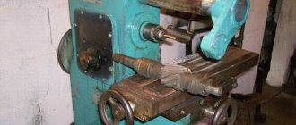
Design and description of the machine components
bed
The bed of the FSSH-1A milling machine is a rigid cast box-shaped structure, covered with a flat cast iron table. Guides for mounting the main movement drive are fixed inside the frame. The electrical equipment of the machine is mounted in the niche of the frame. A welded version of the frame is allowed.
Table
The table is a cast iron reinforced with stiffening ribs. The table is rigidly fixed to the frame.
When working using a template, the lower ramp ring 8 is installed on the table (see Figure 4).
It is possible to use a ramp ring with a collar diameter different from that supplied with the machine.
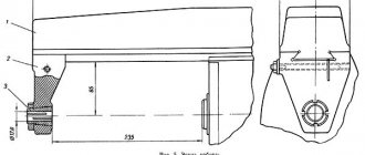
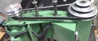
Drive of the main movement of the milling machine FSSH-1A
The main movement drive consists of:
- two-speed electric motor 18;
- poly V-belt transmission 19;
- spindle head connected to the sub-motor plate by 15 rods 3.
The belt is tensioned with screw 3 (Figure 2).
The spindle head consists of a box-section cast iron body 4, in which a spindle 1 is mounted on rolling bearings. The bearings are preloaded by a set of springs 2.
At the upper end of the spindle shaft 1 there is a conical hole (Morse taper No. 4) for installing a mandrel 11, which is secured with a differential nut 12. The spindle shaft is locked from rotation by a lock 5, which is interlocked with the drive by means of a screw 6 and a switch 7.
The spindle head with an electric motor has a vertical adjustment movement of up to 100 mm through gear 13, 14 and screw gears 16, 17 with fixation in the required position .
The cutting tool is secured to the mandrel using a set of spacer rings 9 using a nut 10.
A very important element of the machine is the spindle attachment (Mandrel). On the FSSH-1A machine, the mandrel is removable. Particular attention is paid to attaching the mandrel to the spindle using a differential nut. Taking into account the different thread pitch on the mandrel and spindle, when fastening with a differential nut, the cones are brought closer together and axially tightened. We recommend not removing the mandrel unless absolutely necessary. Well, if you still decide to remove the mandrel, then you need a special key for this (the machine is not equipped with this key), and do not forget to lock the spindle shaft with a lock. The use of original spacer rings on the mandrel is especially important for the operation of the machine. We strongly recommend using only “original” rings. These rings are made with extreme precision, and the seats (end part) are ground. Using non-factory rings (a typical mistake) usually leads to bending of the mandrel after clamping the cutter nut. This curvature may not be noticeable to the eye, but when rotating even at 3000 rpm, a rather strong beating and vibration occurs. This is a very common mistake.
Movable tenon-cutting carriage for milling machine FSSH-1A
The movable tenoning carriage includes:
- cast iron plate, which is the front of the table;
- clamp with ruler;
- stops limiting the amount of travel of the carriage.
The carriage plate is movable along guides fixed on the machine table;
The movable mount of the carriage is made on rolling bearings. By means of stops, the magnitude of the stroke and its location relative to the machine spindle are set;
The carriage plate has holes for attaching a clamp with a ruler and thrust clamps in various positions.
Design Features
The main design feature of this machine is that the cutting tool is placed in a special housing with a pipe, which is designed to remove dust and chips that arise during operation.
Dimensions, weight and general appearance
The weight of the unit is 810 kg, and the dimensions are as follows:
- length – 100 cm;
- width – 111 cm;
- height – 127 cm.
Tool protection design
Cutting tool protection is a structure consisting of the following elements:
- bracket;
- exhaust pipe;
- slider;
- guide rulers.
When moving the protective mechanism, the operating instructions recommend using the control flywheel. With its help, you can move the protection line mechanism towards the feed. The safety shield is installed in the extreme upper and lower positions using special screws. To fix parts in a certain position, a clamp with a ruler is used. Using clamping screws, the master can lock any movable security mechanisms.
List and location of controls
The equipment is equipped with a compact control panel. The control panel has 2 buttons to turn the drive on and off, as well as 2 signal lights of white and green colors. All electrical equipment is located in the niche of the frame.
In addition, the machine has the following controls:
- handles for securing the rulers and the protection housing;
- spindle stop;
- a flywheel that moves the spindle head;
- handle for clamping the spindle head.
The machine also has buttons for fixing the ruler bracket and tool guard.
Arrangement of components
The main components of the unit are arranged as follows:
- Bed. Cast iron structure covered with a flat cast iron table.
- The table is also a cast iron structure, reinforced with stiffening ribs.
- The carriage is movable, tenon-cut, consisting of a cast-iron plate, a clamp with a ruler, as well as stroke limiters.
The carriage is movably mounted using rolling bearings.
Component mechanisms and units of the unit
The drive of the main movement of the equipment consists of the following parts:
- two-speed motor;
- spindle head connected to the submotor plate;
- V-ribbed transmission.
The spindle head itself consists of a cast iron body in which the spindle itself is mounted on rolling bearings. The spindle attachment has a removable mandrel.
Kinetic scheme
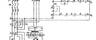
Electrical diagram
Electrical equipment
The two-speed electric motor is connected to the spindle head by a belt drive. The spindle braking and acceleration time is 2.3 seconds. The engine is equipped with protection against overheating and short circuit. The presence of interlocks in the electrical circuit provides protection to the operator.
Electrical equipment of the FSSH-1A machine
General information
The electrical equipment of the FSSH-1A(K) machine includes a two-speed asynchronous electric motor with a squirrel-cage rotor as a spindle drive.
The electrical equipment of the machine is designed for the following values of alternating current:
- power circuit ~ 380V, 50 Hz
- 110V control circuit
- 22V alarm circuit
Electrical equipment provides the possibility of its operation in fire zones of class P-II in accordance with the classification of the “Rules for the Construction of Electrical Installations” PUE. The electrical equipment of the FSSh-1A(K) machine is presented in the electrical circuit diagram (Figure 7) and the electrical connection diagram (Figure 8). The list of elements for the diagram is given in Table 7.1. Protection of power circuits from short circuit currents is carried out by automatic switch QF, control and signaling circuits by fuses FU1, FU2, FU3, and from long-term overloads of the electric motor by thermal relays KK1 and KK2.
The control panel is equipped with signal lamps and machine drive control buttons.
The operation of the machine is controlled from the buttons SB1 and SB2. Electrical control equipment is located in a niche located directly on the machine itself.
The circuit provides for electrodynamic braking of the M engine after it is turned off (electrodynamic brake). The engine should slow down in no more than 6 seconds. The permissible machine braking frequency is no more than 10 braking times per hour.
The required deceleration rate (speed) is set by the regulator located on block A, separately for each selected rotation speed of the electric motor M.
The operating principle of electrodynamic braking is based on the flow of reverse current through the stator windings of the motor. The flow time is regulated using a time relay. It is necessary to use the time relay correctly; incorrectly setting the braking time can lead to damage to the electric motor. The time relay must be periodically reconfigured depending on the cutting conditions, the tool used (its size), spindle speed, etc. If engine braking is not essential in operation and you can do without it, then it is better to turn off the time relay altogether, eliminating unnecessary work.
The selection of spindle rotation speed is carried out by switch SA, through additional contacts 16, 17, 18 of block A.
The FSSh-1A machine has four spindle rotation speeds: 3000, 4500, 6000, 9000 rpm. The main drive uses a two-speed asynchronous electric motor. The switch sets the first or second rotation speed. When switching, one of two motor winding connection schemes is selected:
- in position I - triangle connection diagram (motor shaft speed 1420 rpm);
- in position II - star connection diagram (motor shaft speed 2820 rpm)
The rotation speed of the milling spindle is also selected by moving the drive belt along two pulley stages:
- First pulley stage - spindle speed 3000, 4500 rpm
- Second pulley stage - spindle speed 6000, 9000 rpm
Putting the FSSh-1A milling machine into operation
Before starting the machine, it is necessary to externally check the quality of installation and the reliability of the grounding circuits. Turn on the QF circuit breaker, and lamp 11 HL1 lights up, indicating that voltage is supplied to the machine circuit.
By pressing the SB2 button (4-5), turn on the rotation of the electric motor M; at the same time, the HL2 lamp lights up, indicating that the cutter rotation drive is turned on. Stopping with braking occurs by pressing button SB1 (3-4).
Blocking
The electrical circuit of the machine provides the following interlocks: the start of the machine is interlocked with the cutting tool guard (SQ1), the spindle lock (SQ2).
Blocking is achieved by introducing contacts SQ1, SQ2 into the power circuit of the KM1 coil.
Zero protection is carried out by block contacts of the magnetic starter KM1 (4-5).
Inability to turn on the M electric motor during braking. This is achieved by introducing a breaking contact into the switching circuit of the KM1 coil - the KM2 starter (12-13).
The circuit provides for interlocking with a workshop exhauster installation.
Grounding
When installed, the machine must be reliably grounded in accordance with applicable rules and regulations. To do this, the contact clamp of the external protective circuit must be connected to the workshop grounding circuit.
ATTENTION: It is forbidden to press the stop button SB1 when initially starting the machine and phasing it if the electric motor has not reached full speed.
Technical characteristics of the milling machine FSSH-1A(K)
| Parameter name | FSSH-1A(K) |
| Basic machine parameters | |
| The greatest thickness of the processed workpiece (the greatest milling depth), mm | 100 |
| Nominal table dimensions, mm: | 325 x 1000 |
| Maximum vertical relative movement of the spindle, mm | 100 |
| Internal Morse taper of spindle | №4 |
| Maximum width of the workpiece mounted on the carriage with a tenon depth of 100 mm, mm | 700 |
| Nominal diameter of spindle attachment, mm | 32 |
| The largest diameter of the cutting tool, mm | 250 |
| Maximum stroke of the tenoning carriage, mm | 926 |
| Table height from the floor, not less, mm | 860 |
| Optimal diameter of round workpiece, mm | 90 |
| Rated spindle speed at rated motor power, rpm | 3000, 4500, 6000, 9000 |
| Electrical equipment of the machine | |
| Type of supply current | 380V 50Hz |
| Number of electric motors on the machine, pcs. | 1 |
| Electric motor - rated power, kW | 4,0/ 4,75 |
| Electric motor - rated speed of electric motor, rpm | 1420/ 2820 |
| Rated voltage of control circuits, V | 110 |
| Dimensions and weight of the machine | |
| Machine dimensions (length x width x height), mm | 1000 x 1110 x 1270 |
| Machine weight, kg | 810 |
- Single-spindle milling machines with tenoning carriage FSSH-1A(K). Operating manual FSSH-1A(K).00.000 RE, Kirov, 2005
- Single-spindle milling machines with tenoning carriage FSSH-1A. Operating manual FSSH-1A.00.000-00 RE, Dnepropetrovsk, 2005
- Amalitsky V.V. Woodworking machines and tools, 2002
- Afanasyev A.F. Wood carving, Technique, Tools, Products, 2014
- Bobikov P.D. DIY furniture, 2004
- Borisov I.B. Wood processing, 1999
- Jackson A., Day D. Woodworking Bible, 2015
- Golden Book of woodworking for the owner of a country plot, 2015
- Ilyaev M.D. Wood carving, Master's lessons, 2015
- Komarov G.A. Four-sided longitudinal milling machines for wood processing, 1983
- Kondratyev Yu.N., Pitukhin A.V... Technology of wood products, Product design and calculation of materials, 2014
- Korotkov V. I. Woodworking machines, 2007
- Lyavdanskaya O.A., Lyubchich V.A., Bastaeva G.T. Basics of woodworking, 2011
- Lyubchenko V.I. Thicknessing machines for wood processing, 1983
- Manzhos F.M. Wood cutting machines, 1974
- Rasev A.I., Kosarin A.A. Hydrothermal processing and preserving of wood, textbook, 2010
- Ryzhenko V.I. The Complete Encyclopedia of Wood Art, 2010
- Rykunin S.N., Kandalina L.N. Woodworking technology, 2005
- Simonov M.N., Torgovnikov G.I. Debarkers, 1990
- Soloviev A.A., Korotkov V.I. Setting up woodworking equipment, 1987
- Sukhanov V.G. Circular saws for sawing wood, 1984
- Fokin S.V., Shportko O.N. Woodworking, Technologies and equipment, 2017
- Hilton Bill Woodworking, The Complete Guide to Stylish Home Furniture Making, 2017
Bibliography:
Related Links. Additional Information
- Directory of woodworking machines
- Manufacturers of woodworking machines and equipment
- Manufacturers of household woodworking machines
- Manufacturers of chipping machines
- Classification of woodworking machines
- Machines for longitudinal cutting of lumber
- Sawmill frames. Classification
Home About the company News Articles Price list Contacts Reference information Interesting video KPO woodworking machines Manufacturers
Specifications
These include the following indicators:
- voltage and frequency of the supply network (380 V, 50 Hz);
- supply voltage for control and signaling circuits (110 and 22 V, respectively).
- depth to which milling can be carried out (100 mm);
- width and diameter of the workpieces used (no more than 700 mm and 90 mm, respectively);
- stroke length of the tenoning block (926 mm);
- the amount of vertical movement of the spindle (100 mm);
- diameter of the cutting tool used (no more than 250 mm);
- power and frequency of the electric motor (4.0; 4.75 kW and 1420 and 2820 rpm, respectively);
- the number of revolutions per minute made by the spindle (3000, 4500, 6000 and 9000);
- diameter of the spindle attachment (no more than 32 mm).
Overall dimensions in mm 1000 x 1110 x 1270 and weight in tons 0.81.