Information about the manufacturer of the cantilever milling machine 6R13F3, 6R13F3-37
Manufacturer of vertical console milling machines 6R13F3 , 6R13F3-37 Gorky Milling Machine Plant , founded in 1931.
Metal-cutting machines at the Votkinsk Machine-Building Plant have been produced since 1956. These are vertical milling machines 6N13 , VM127 , VM127M , universal milling machines VM130 , VM133 , horizontal milling machines with CNC VM500PMF4 , VM501PMF4 , as well as a table lathe Universal-V .
Currently, JSC Votkinsk Plant is the leading enterprise of the rocket and space complex and a manufacturer of a wide range of civilian products.
Today the 6R13F3 cantilever milling machine produces:
- Stanochny Park LLC;
Machine tools produced by the Votkinsk Machine-Building Plant
- 6N13P
- vertical cantilever milling machine 400 x 1600 - 6R13F3
- vertical cantilever milling machine with CNC 400 x 1600 - 6Р13рФ3
- vertical cantilever milling machine with CNC 400 x 1600 - VM127
- vertical cantilever milling machine 400 x 1600 - VM127M
- vertical cantilever milling machine 400 x 1600 - VM-130
- wide-universal milling machine 250 x 630 - VM-501PMF4
- horizontal milling machine with CNC and ASI Ø 250 - Universal-V
- tabletop screw-cutting lathe Ø 150
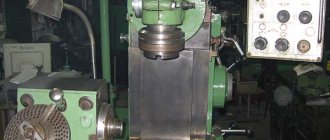
6Р13Ф3 vertical cantilever milling machine with CNC. Purpose and scope
6R13F3 vertical cantilever milling machine with CNC was put into production in 1972. The following machines were designed on the basis of this model:
- 6r13f3-37 - cantilever milling machine with N33-2M CNC device;
- 6р13рф3 - cantilever milling machine with a turret head;
- GF2171 - cantilever milling machine with a tool magazine
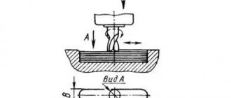
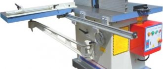
6R13F3 vertical milling machine is intended for processing a variety of complex profile parts made of steel, cast iron, and difficult-to-cut non-ferrous metals, mainly with face and end mills, drills in medium-scale and small-scale production.
The milling machine model 6Р13Ф3-37 is equipped with the ability to process products in program control mode simultaneously along three coordinates: longitudinal and transverse (moving the table and slide with the workpiece) and vertical (moving the slide with the tool).
Operating principle and design features of the machine
Programmable vertical movement (Z coordinate) is carried out by the movement of the slider. 6R13F3 CNC milling machine has only installation movement, which excludes positioning and operation in the tracking mode of the console, which has a significant mass. The processing accuracy increases, since the console is always clamped during the cutting process.
6R13F3 machine is equipped with servo-adjustable feed drives with high-torque DC electric motors.
The use of servo adjustable drives with DC motors ensures a rapid table movement speed of up to 4.8 m/min and eliminates part rejection during contour processing in the event of a feed drive failure along one of the coordinates.
Centralized lubrication of guides has been introduced.
The machine uses an electromechanical tool clamping device, which provides a stable clamping force of 2000 kg.
For remote equipment there is ready-made electrical wiring with plug connectors.
Roughness of the processed surface Rz = 20 µm.
The accuracy class of the machine is N according to GOST 8-82.
Developer: Gorky Machine Tool Production Association.
The quality category is the highest.
P series cantilever milling machines
- 6Р12, 6Р12Б
- vertical cantilever milling machine 320 x 1250 - 6Р13, 6Р13Б
- vertical cantilever milling machine 400 x 1600 - 6R13F3
- vertical cantilever milling machine with CNC 400 x 1600 - 6Р13рФ3
- vertical cantilever milling machine with CNC 400 x 1600 - 6Р82
- universal console-milling machine with a rotary table 320 x 1250 - 6R82G
- horizontal cantilever milling machine 320 x 1250 - 6Р82Ш
- universal cantilever milling machine 320 x 1250 - 6Р83
- universal cantilever-milling machine with a rotary table 400 x 1600 - 6R83G
- horizontal cantilever milling machine 400 x 1600 - 6Р83Ш
- universal universal cantilever milling machine 400 x 1600
Cantilever milling machines. General information
Horizontal and vertical cantilever milling machines are the most common type of machines used for milling work.
Cantilever milling machines get their name from the cantilever bracket (console), which moves along the vertical guides of the machine bed and serves as a support for the horizontal movements of the table. The standard sizes of cantilever milling machines are usually characterized by the size of the working (mounting) surface of the table. Cantilever milling machines can have a horizontal , universal (widely universal) and vertical design with the same size of the working surface of the table. The combination of different versions of the machine with the same basic dimensional characteristics of the table is called the dimensional range of machines .
In the USSR, the production of cantilever milling machines of five standard sizes was mastered: No. 0; No. 1; No. 2; No. 3 and No. 4 , and a full range of machines was produced for each size - horizontal, universal and vertical. Each machine of the same size range had the same designation in the code, corresponding to the size of the working surface of the table.
Depending on the size of the working surface of the table, the following sizes of cantilever milling machines are distinguished:
| Size | Range of machines | Table size, mm |
| 0 | 6Р10, 6Р80, 6Р80Г, 6Р80Ш | 200 x 800 |
| 1 | 6N11, 6N81, 6N81G; 6Р11, 6Р81, 6Р81Г, 6Р81Ш | 250 x 1000 |
| 2 | 6M12P, 6M82, 6M82G; 6Р12, 6Р82, 6Р82Ш; 6T12, 6T82, 6T82G, 6T82Sh | 320 x 1250 |
| 3 | 6M13P, 6M83, 6M83G; 6Р13, 6Р83; 6T13, 6T83, 6T83G | 400 x 1600 |
| 4 | 6M14P, 6M84, 6M84G | 500 x 2000 |
In accordance with the size of the table, the overall dimensions of the machine itself and its main components (bed, table, slide, console, trunk), the power of the electric motor and the magnitude of the greatest movement (stroke) of the table in the longitudinal direction, the slide in the transverse direction and the console in the vertical direction change.
Designation of cantilever milling machines
6
— milling machine (group number according to ENIMS classification)
R
– series (generation) of the machine (B, K, N, M, R, T)
1
– subgroup number (1, 2, 3, 4, 5, 6, 7, 8, 9) according to the ENIMS classification (1 - vertical milling)
2
– machine version – standard size (0, 1, 2, 3, 4) (3 – work table size – 400 x 1600)
Letters at the end of the model designation
G
– horizontal cantilever milling machine with a fixed table
TO
– a machine with a copying device for processing curved surfaces
B
– a machine with increased productivity (increased range of spindle speeds, table feeds and increased power of the main movement engine).
P
– machine accuracy - (n, p, v, a, s) according to GOST 8-XX
Sh
– widely universal machine
F1
– a machine with a digital display device (DRO) and preset of coordinates
F2
– machine with CNC positional numerical control system
F3
– machine with contour (continuous) CNC system
F4
– multi-purpose machine with CNC contour system and tool store
Where and for what are milling machines used?
This router has a CNC device model N33-2M. With the help of which it is possible to produce and control the processing of metal products remotely along vertical, longitudinal and horizontal coordinates. With this, you can transport the table on which the metal element is processed, as well as move the slide with the tool.
The element is moved up and down in remote programs by moving the slider. The 6R13F3 CNC panel has an installation movement. Since the console is completely compressed at the moment of processing the metal product, the element is cut as accurately as possible.
The 6R13F3 CNC machine is equipped with electric feed drives, which are servo-adjustable. These drives provide a continuous supply of current, due to which the table can move quite quickly (up to 4.80 m/min.). Due to this, the option of manufacturing a defective part is eliminated if one of the mechanism drives stops functioning. The device has a centralized lubrication system for all guide elements. To clamp a metal product, the mechanism contains an electromechanical tool, the clamping force of which is more than 2,000 kilograms.
The machine is designed in accordance with all norms and requirements of GOST standards. The equipment is equipped with its own electrical wiring in case finishing work needs to be carried out in a place where there is no outlet. After finishing the metal element, the roughness level is approximately 20 microns.
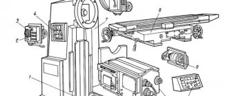
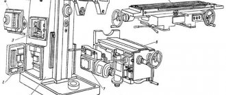
6Р13Ф3 Arrangement of components of a CNC console milling machine
Location of components of the 6р13ф3-37 CNC milling machine
Location of components of the 6р13ф3-37 CNC milling machine
List of main components of the 6R13F3 cantilever milling machine
- 1. Bed - 6Р13Ф3-37.10
- 2. Gearbox - 6Р13Ф3-37.25
- 3. Console - 6Р13Ф3-37.61
- 4. Electrical box - 6Р13Ф3-37.068
- 5. Table and slide - 6Р13Ф3-37.70
- 6. Electrical equipment - 6Р13Ф3-37.80
- 9. Spindle head - 6Р13Ф3-01.38
- 10. Gearbox - 6Р13Ф3-01.32
- 11. Gearbox - 6Р13Ф3.50
- 12. Guide protection - 6Р13Ф3.74
- 14. Cooling - 6Р13Ф3.90
- 15. Fencing - 6Р13Ф3.91
- 17. Protective device - 6M13P.91
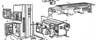
Location of controls for a CNC machine model 6Р13Ф3
Location of controls for milling machine 6р13ф3-37
Location of controls for milling machine 6р13ф3-37
List of machine controls 6Р13Ф3 and their purpose
- Ram travel limiting cams
- Tool release button
- Tool Clamp Button
- Cooling pump switch
- Toggle switch for turning on the Z coordinate
- Toggle switch for turning on the Y coordinate
- X coordinate switch
- Technological stop toggle switch
- Toggle switch for manual and automatic operating modes
- Feed rate selector switch
- Manual longitudinal movement of the table
- Feed switch
- —
- Toggle switch for setting coordinates to zero position
- Start Program button
- Button for stepwise movement of nodes
- Spindle start button
- Console Up button
- Stop spindle button
- Console Down button
- Z-coordinate zeroing cams
- X-coordinate zeroing cams
- Console clamp handle on frame
- Longitudinal stroke limiting cams
- All stop button
- Speed indicator
- Spindle Jog button
- Gear shift knob
- Console stroke limiting cams
- Manual vertical movement of the console
- Handle for raising and lowering the fence
- Y-coordinate zeroing cams
- Table cross travel limiting cams
- All stop button
- Manual lateral movement of the table
Description of the design of the main components of the 6R13F3 CNC milling machine
Machine bed
The bed is the main base unit on which the components and mechanisms of the machine are mounted.
The rigid structure of the frame is achieved due to the developed base and a large number of ribs. Its front body has vertical guides along which the console moves. To measure the amount of installation movement of the console, a ruler is attached to the frame.
To limit the travel of the console, limit switches are located in the left niche of the frame. In the upper part of the frame body on the right side there is a window through which access to the oil pump and gearbox is provided. To select the required speed, a gearbox is installed on the left side of the frame. The spindle head is fixed on the mating plane of the frame neck. There is an oil reservoir inside the frame body. The frame is installed on the base and bolted to it.
Machine speed box
The gearbox is used to communicate to the spindle various rotation speeds during cutting.
The bearings and gears of the gearbox are lubricated by a plunger pump located inside the gearbox.
Gearbox
Provides 18 spindle speeds and allows you to select the required speed without sequentially passing through intermediate stages.
The gears are switched as follows: handle 28 (sheet 14, Fig. 4) is lowered down until the handle pin comes out of the fixing groove and pulled away from you until it stops. By turning the dial, pos. 26, set the required number of revolutions against the indicator arrow. In this case, the click of the latch means that the dial is fixed in this position. Press the “Push” button, pos. 27, return the handle with a smooth movement to its original (starting) position.
The gearbox is lubricated from the gearbox plunger pump.
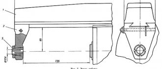
Machine spindle head
The spindle head consists of three main elements: a slide, a gearbox, and a slider with a spindle.
The slide is centered in the annular recess of the bed neck and is attached to it with four bolts. The slider with the spindle moves along the rectangular guides of the slide - Z coordinate.
The gearbox serves to transmit the main (rotational) movement from the gearbox to the spindle through a pair of bevel and three cylindrical wheels.
The movement of the slider with the spindle according to the program is carried out from a high-torque motor through a gearbox made of a pair of cylindrical wheels (Fig. 8) and a “screw-nut” transmission.
To carry out manual movement of the slider, a terminal is provided - hexagon I (Fig. 7).
Table and slide (Fig. 9, 10 and II)
The table and slide provide movement of the table along the X and Y coordinates (longitudinal and transverse).
When moving along the X coordinate, the table receives movement from a high-torque motor of the PBV112LGUZ type through a single-stage gearbox with a gear ratio i = 1:2 and a “screw-nut” transmission.
The ball screw for longitudinal movement of the table rotates in ball bearings installed on the left side in the bracket, and on the right side in the gear housing.
The screw nuts are rigidly fixed in a bracket attached to the table.
The gearbox for the longitudinal movement of the table has a transformer of the BTM-1V type, which is a feedback sensor.
The table is moved in the Y coordinate by a drive mounted in the console. The ball screw for the transverse movement of the table is installed in the console body.
For manual movement of the table there is a hexagonal pin 2 (Fig. 9).
The gap in the table and slide guides is selected using wedges. To adjust the gap, see the “Adjustment” section.
Console of CNC milling machine 6Р13Ф3
The console is the basic unit that combines the drives for the vertical and transverse movements of the table.
Along the vertical guides of the frame (dovetail profile), the console provides vertical installation movement. Along the horizontal guides of the rectangular profile console, the “Table and Slide” unit is moved in the transverse direction (Y coordinate).
A two-stage gearbox for transverse movement of the table with a gear ratio i = 1:2 is mounted in the depth of the console.
The table moves from a high-torque electric motor type PBV112LGUZ through a gearbox and a “screw-nut” transmission.
The cylindrical helical wheels are made as prefabricated to eliminate the lateral gap in the gearing.
The gearbox contains a rotating transformer of type VTM-1B, pos. 1 (Fig. 13).
An asynchronous electric motor of type 4A90LA for vertical installation movement is installed on the right side of the console body. The movement is carried out through a worm pair and a screw gear.
To lubricate the machine's moving guides, gears and bearings, the console has an oil reservoir and a VT II-IIA type lubrication pump, which is powered by an AOL-21-4 type engine.
The horizontal guides of the console are covered at the front with telescopic protection, and at the rear with aprons attached to the frame and the rear end of the slide.
Machine operation with electromechanical tool clamping
The electromechanical tool clamping device is controlled in the following sequence:
- press button 3 (see Fig. 3) “tool clamp”;
- turn on the spindle with button 17 “Start spindle”
When squeezing the tool, you must:
- turn off the spindle with button 19 and make sure that the spindle stops;
- press button 2 “Tool release” and hold until the milling mandrel comes out of the spindle to a length of no more than 15...20 mm.
Otherwise, the spline roller may be completely turned out of the rod. Then, when clamping the tool, the rod must be pressed upward so that the threaded end of the roller is screwed into the threaded hole of the rod.
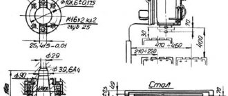
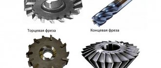
Installation of cutters in mandrels is carried out depending on their size and type according to Fig. 15, 16.
The tool in the mandrel is secured outside the machine using replaceable cleaning rods. The mandrel has an outer cone 7:24 and an internal “Morse No. 4.” For fastening tools with Morse cones No. 2,3,5, replaceable adapter sleeves 2 and 3 are used. The presence of replaceable cleaning rods with 4 lead threads M10, M12, M16, and M20 allows carry out processing with end mills (with a tapered shank) respectively Ø 16, Ø 20, Ø 40, Ø 50.
Gripper I must be installed in such a way that its T-shaped groove is perpendicular to the leading grooves of the mandrel.
Insert the mandrels with the tool into the conical hole of the spindle and connect them to the T-shaped end of the rod by turning at an angle of 90°, turn on the “Tool Clamping” button. The end of the clamping is determined by pushing the jaw couplings.
The tool must be clamped at a spindle speed of no higher than 40 rpm.
Purpose and operating features of a vertical milling machine with CNC 6r13f3
The CNC milling machine 6р13ф3 is a device with a high quality category. The machine can carry out work on milling parts. The device is capable of performing work on drilling products when using the appropriate tool. The unit processes parts made of cast iron, steel and various alloys of ferrous and non-ferrous metals.
Device characteristics
6р13ф3 has wide functionality. In addition to processing cast iron and steel products, the machine can process:
- cold rolled sheets;
- parts that are difficult to process, made of non-ferrous metals;
- hot rolled sheets;
- complex products by drilling.
Hot rolled metal sheets
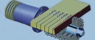
The unit can process various parts by milling with face and end mills.
The device is used in small and medium-sized production runs. Its weight reaches 4449 kg, and the general parameters for length, width and height are 345 * 296.5 * 397 cm.
The device has a CNC that allows:
- move the slide from the product and the work table in the longitudinal and transverse directions;
- move the slider with the cutter in the vertical direction.
Main characteristics of the machine:
- table surface dimensions - 40*160 cm;
- the load that the table can withstand is 300 kg;
- number of grooves - 3;
- feed limit indicators - 3-4799 mm/min;
- accuracy indicators for transverse movement 0.04 mm, vertical - 0.065, longitudinal - 0.04;
- longitudinal, transverse and vertical movement of the table - 100*40*42 cm, respectively;
- the rate of rapid movement of the slider together with the table is 4799 mm/min;
- feed per pulse - 0.01 mm;
- maximum drilling diameter - 30 mm;
- The maximum diameter of the end mill is 125 mm.
The 6r13f3 milling machine is equipped with 6 electric motors:
- lubricating - 0.26 kW;
- those that clamp the tool - 0.17 kW;
- intended for moving the console - 2.1 kW;
- engine for the cooling pump - 0.12 kW;
- main motion drive - 7.4 kW;
- motor designed for feeding along 3 axes - 2.1 kW.
The device is equipped with electrical wiring equipped with connectors for plugs.
Features of the CNC machine
The device is equipped with numerical control, thanks to which:
- issues a chain of management commands;
- information is displayed;
- the functions of the device are monitored and its diagnostics are carried out;
- operation of all machine automation modes is ensured;
- control programs are entered and turned off and adjusted.
CNC system
The vertical milling machine with CNC 6r13f3 includes:
- linear and circular interpolation system;
- reverse type sensor;
- servo type drive.
Using CNC, the operator has the opportunity to control the tool and visually track the direction of its movement. At the same time, he does not need to constantly test the program on the device.
The operator of this CNC device receives all the necessary data through 5 main indicators:
- “View A”, which is the main indicator containing the main information;
- "View B", containing additional information;
- "Errors";
- "Management programs";
- "Options".
Using the F1 and further keys, the operator installs the desired control program.
Features of the electrical equipment of the machine
The CNC of a machine tool is an integral part of its electrical equipment. It is a three-phase network with a frequency of 50 Hz and operating at a voltage of 380 V.
Since the unit is expensive equipment, the developers provide a special network protection system for it.
At some enterprises, to protect the machine from power supply failures, it is connected to stabilizers or machine converters. Thanks to these devices, the device receives the necessary power and at the same time is protected from sudden surges in power supply.
Any vertical milling machine with CNC 6р13ф3 is equipped with a control station, which is activated by means of an input automatic machine. On the front side of the station there are handles that control the operation of the machine.
The system provides several types of voltage:
- 55V DC brake circuit;
- power circuit having three phases with an alternating current of 380 V;
- for powering electric motors with direct current 47 V;
- for local lighting with 24 V AC current;
- for control circuits with alternating and direct current 109 and 23 V, respectively.
Electric motor of the machine
Scheme of a CNC machine 6р13ф3
The unit is characterized by a rigid base. This is ensured by the fact that its frame has a well-developed base with numerous ribs.
There are vertical guides in the front part of the bed. The console moves along them.
There is a window at the top of the frame. Through it the operator gains access to the pump and gearbox. Switches equipped on the frame limit the movement of the console.
The spindle head includes the following elements:
- sled;
- gearbox;
- slider
The slides are mounted to the frame with bolts, and their alignment occurs in its neck. The movement of the slide with the slider occurs along rectangular guides.
The console of the device serves as its basic element. Its role is reduced to combining the drives for vertical and transverse movements of the table. There is a two-stage gearbox inside the console.
Related video: CNC vertical milling machine
promzn.ru
Electrical equipment of the 6R13F3 machine. General information
The electrical equipment is located on the machine in the control station and also includes the NZZ-2M numerical control system.
The control station is used to house switching devices and electrical circuit protection devices.
Electrical equipment is powered through a control station from a three-phase alternating current network with a voltage of 380 V and a frequency of 50 Hz. The permissible fluctuation of the supply voltage is 15% ± 10% of 380 V. In case of large fluctuations in the network voltage, it is necessary to power the CNC device and the electrical automation of the machine from a separate stabilizer. It is possible to power a group of CNC machines from a separate stabilizer or a separate machine converter.
The following voltages are used on the machine:
- power circuit - three-phase, alternating current 380 V, frequency 50 Hz;
- control circuit - AC 110 V, 50 Hz;
- local lighting circuit - alternating 24 V, 50 Hz;
- control circuit - 24 V DC;
- electrodynamic braking circuit - 55 V DC;
- power supply for electric feed motors - 48 V DC.
The power supply to the control station is turned on by the Input Automatic (I), which is controlled using a handle located on the door of the control station.
The following electric drives are installed on the machine:
- electric drive of the main movement; carried out from an asynchronous motor type 4А132S4У3, 7.5 kW, 1450 rpm, 380 V, designation according to scheme M1 (A02-5I-4, 7.5 kW, 1450 rpm, 220/380 V);
- electric drive for adjustment movement of the console; carried out from an asynchronous motor type 4A90LA, 2.2 kW, 1500 rpm, 380 V, designation according to the M2 scheme;
- electric drive for tool clamping; carried out from an asynchronous motor type 4ААС56В4У3, 0.18 kW, 1500 rpm, 380 V, designation according to the M4 scheme;
- electric drive of the cooling pump; performed by an asynchronous motor XA14-22M (0.12 kW; 2800 rpm; 380 V; designation according to scheme M3;
- electric lubrication motor type AOL-21-4, 0.27 kW, 1500 rpm; 380 V; designation according to the M5 scheme
- The electric drive of the longitudinal feed (X coordinate) is carried out from a DC electric motor type PBB-112L 2.2 kW 1000 rpm, 110 V, designation according to the M7 diagram.
The feed drive electric motor is controlled by the CNC through a thyristor converter type 3T6S-8-PBB-112LU4.
Speed feedback is provided by a tachogenerator built into the electric motor with excitation from permanent magnets. Designation according to the M6 scheme.
Position feedback is provided by a rotating transformer type BTM-1V
- the electric drive of the transverse feed (Y coordinate, slide) is carried out similarly to the X coordinate. Designation of devices according to the diagram: electric motor - M9, tachogenerator - M8, rotating transformer - P2;
- The electric drive of the vertical feed (Z coordinate, slider) is carried out similarly to the X coordinate. Designation of the devices according to the diagram: electric motor - M11. tachogenerator - M10, rotating transformer - PZ.
Factors leading to the choice of a 6R13F3 machine
The first factor for choosing a machine is its standard size, which indicates the maximum dimensions of the workpiece, and in milling machines this is the size of the work table (or, for example, in lathes, the height of the centers). This machine has a working table size of 400x1600.
The second factor is the total cost of the machine (purchase and installation). The total cost of the machine is about 520 thousand rubles. and varies depending on the CNC device model.
It is also required, when choosing a machine, to pay attention to the possibility of automatic tool change, but this machine does not have this function. The accuracy of the machine, according to the classification, is high.
The machine can be equipped with CNC systems that are the easiest to learn, but not for use since it has a small number of cycles and has a greater bias towards the use of conventional G codes in 3rd coordinates.
From the above we can conclude that the machine is suitable for medium-scale production because there is no automatic tool change, but it has a CNC system that allows you to automate the processing of one setup (which is not rational to overpay for in small-scale production).
Full list of characteristics of the machine 6Р13Ф3-37
| Accuracy class according to GOST 8-82 | N |
| Basic machine parameters | |
| Dimensions of the working surface of the table (length x width), mm | 400 x 1600 |
| Maximum load on the table (center), kg | 300 |
| Number of T-slots Dimensions of T-slots | 3 |
| Maximum longitudinal movement of the table (X), mm | 1000 |
| Maximum lateral movement of the table (Y), mm | 400 |
| Maximum vertical installation movement of the table, mm | 420 |
| Distance from the spindle axis to the vertical guides of the bed (overhang), mm | 500 |
| Minimum distance from the rear edge of the table to the bed guides, mm | 100 |
| Distance from the end of the spindle to the working surface of the table, mm | |
| Maximum vertical movement of the slider (Z), mm | 250 |
| Working feed limits. Longitudinal, transverse, vertical, mm/min | 3..4800 |
| Speed of rapid movement of the table and slider, mm/min | 4800 |
| The smallest and largest distance from the end of the spindle to the table mm | 70…490 |
| Feed per impulse, mm | 0,01 |
| Positioning accuracy along the X axis, mm | 0,065 |
| Positioning accuracy along the Y, Z axis, mm | 0,040 |
| Largest drilling diameter, mm | 30 |
| The largest diameter of the end mill, mm | 40 |
| Largest diameter of end mill, mm | 125 |
| Spindle | |
| Number of spindles | 1 |
| Spindle speed, rpm | 40…2000 |
| Number of spindle speeds | 18 |
| Maximum torque, kgf.m | 62,8 |
| Spindle end | GOST 836-72, 7:24 |
| CNC system | |
| CNC type | N33-2M |
| Dimensioning method | In increments |
| Types of interpolation | Linear Circular |
| Number of simultaneously controlled coordinates for linear / circular interpolation | 3/2 |
| Electrical equipment | |
| Number of electric motors on the machine | 8 |
| Main motion drive electric motor, kW (rpm) | 7,5 (1450) |
| Electric feed drives along the X, Y, Z axes, kW | 2,2 |
| Electric drive for adjustment movement of the console, kW | 2,2 |
| Electric drive for tool clamping, kW | 0,18 |
| Electric drive of the cooling pump, kW | 0,12 |
| Electric pump motor for smearing, kW | 0,27 |
| Total power of electric motors, kW | 16,87 |
| Machine dimensions | |
| Machine dimensions, mm | 3450 x 3970 x 2965 |
| Machine weight, kg | 4450 |
Technical characteristics of the CNC milling machine 6Р13Ф3-37
| Parameter name | 6Р13Ф3-37 | 6R13RF3 |
| Accuracy class according to GOST 8-82 | N | N |
| Basic machine parameters | ||
| Dimensions of the working surface of the table (length x width), mm | 400 x 1600 | 400 x 1600 |
| Maximum load on the table (center), kg | 300 | 300 |
| Number of T-slots Dimensions of T-slots | 3 | 3 |
| Maximum longitudinal movement of the table (X), mm | 1000 | 1000 |
| Maximum lateral movement of the table (Y), mm | 400 | 400 |
| Maximum vertical installation movement of the table, mm | 420 | 380 |
| Distance from the spindle axis to the vertical guides of the bed (overhang), mm | 500 | 500 |
| Minimum distance from the rear edge of the table to the bed guides, mm | 100 | 100 |
| Distance from the end of the spindle to the working surface of the table, mm | 70..450 | |
| Maximum vertical movement of the slider (Z), mm | 250 | — |
| Working feed limits. Longitudinal, transverse, vertical, mm/min | 3..4800 | 20..1200 |
| Speed of rapid movement of the table and slider, mm/min | 4800 | 2400 |
| The smallest and largest distance from the end of the spindle to the table mm | 70…490 | 70…450 |
| Feed per impulse, mm | 0,01 | 0,01 |
| Positioning accuracy along the X axis, mm | 0,065 | |
| Positioning accuracy along the Y, Z axis, mm | 0,040 | |
| Largest drilling diameter, mm | 30 | |
| The largest diameter of the end mill, mm | 40 | |
| Largest diameter of end mill, mm | 125 | |
| Spindle | ||
| Number of spindles | 1 | 6 |
| Spindle speed, rpm | 40…2000 | 40…2000 |
| Number of spindle speeds | 18 | 18 |
| Maximum torque, kgf.m | 62,8 | |
| Spindle end | GOST 836-72, 7:24 | |
| CNC system | ||
| CNC type | N33-2M | N33-1M |
| Dimensioning method | In increments | In increments |
| Types of interpolation | Linear Circular | Linear Circular |
| Number of simultaneously controlled coordinates for linear / circular interpolation | 3/2 | 3/2 |
| Electrical equipment | ||
| Number of electric motors on the machine | 8 | |
| Main motion drive electric motor, kW (rpm) | 7,5 (1450) | 7,5 |
| Electric feed drives along the X, Y, Z axes, kW | 2,2 | Stepper |
| Electric drive for adjustment movement of the console, kW | 2,2 | |
| Electric drive for tool clamping, kW | 0,18 | — |
| Electric drive of the cooling pump, kW | 0,12 | |
| Lubrication pump electric motor, kW | 0,27 | |
| Total power of electric motors, kW | 16,87 | |
| Machine dimensions | ||
| Machine dimensions, mm | 3450 x 3970 x 2965 | 3200 x 2500 x 2450 |
| Machine weight, kg | 4450 | 6900 |
- CNC vertical cantilever milling machine 6R13F3-37. Operating manual 6Р13Ф3-37.00.000 РЭ, 1978
- CNC vertical cantilever milling machine 6R13F3-37. Programming instructions (CNC device - N33-2M with an equidistant calculation unit), 1978
- Avrutin S.V. Fundamentals of Milling, 1962
- Avrutin S.V. Milling, 1963
- Acherkan N.S. Metal-cutting machines, Volume 1, 1965
- Barbashov F.A. Milling business 1973, p.141
- Barbashov F.A. Milling work (Vocational education), 1986
- Blumberg V.A. Milling machine handbook, 1984
- Grigoriev S.P. Practice of coordinate boring and milling work, 1980
- Kopylov R.B. Working on milling machines, 1971
- Kosovsky V.L. Handbook of a young milling operator, 1992, p. 180
- Kuvshinsky V.V. Milling, 1977
- Nichkov A.G. Milling machines (Machinist's Library), 1977
- Pikus M.Yu. A mechanic's guide to repairing metal-cutting machines, 1987
- Plotitsyn V.G. Calculations of settings and adjustments of milling machines, 1969
- Plotitsyn V.G. Setting up milling machines, 1975
- Ryabov S.A. Modern milling machines and their equipment, 2006
- Skhirtladze A.G., Novikov V.Yu. Technological equipment for machine-building industries, 1980
- Tepinkichiev V.K. Metal cutting machines, 1973
- Chernov N.N. Metal cutting machines, 1988
- Frenkel S.Sh. Handbook of a young milling operator (3rd ed.) (Vocational education), 1978
Bibliography:
Related Links. Additional Information
- Milling machines: general information, classification, designation
- Comparative characteristics of cantilever milling machines of the 6N, 6M, 6R, 6T
- Feed box for console milling machines of the 6M : 6M12P, 6M13P, 6M82, 6M83, 6M82Sh, 6M83Sh
- Feed box for console milling machines of the 6P : 6P12, 6P13, 6P82, 6P83, 6P82Sh, 6P83Sh
- Feed box for console milling machines 6T : 6T12, 6T13, 6T82, 6T83, 6T82Sh, 6T83Sh
- Milling machine repair technology
- Adjustment of milling machines
- Friction clutch. Friction shaft. Friction clutches in metal-cutting machines
- Automatic cycles of milling machines (6P12)
- Testing and checking metal-cutting machines for accuracy
- Directory of universal milling machines
- Manufacturers of metal-cutting machines in Russia
- Manufacturers of milling machines in Russia
- Generations of CNC systems. Terms and concepts of CNC systems
- Russian manufacturers of modern CNC systems
- Review of Russian-made CNC systems
- Recommendations for choosing CNC devices
- Problems with modernized CNC machines: tips and tricks from professionals
- Requirements for ensuring stability and safety of machine control systems
- Electrical equipment of milling machines 6T12, 6T13, 6T82, 6T82G, 6T82Sh, 6T83, 6T83G, 6T83Sh
- Electrical equipment of milling machines 6P12, 6P13, 6Р82, 6Р82Г, 6Р82Ш, 6Р83, 6Р83Г, 6Р83Ш, 6Р12Б, 6Р13Б
- Electrical equipment of milling machines 6M12P, 6M12PB, 6M13P, 6M13PB, 6M82, 6M82Sh, 6M82GB, 6M83, 6M83Sh
- Electrical equipment of milling machines 6T10, 6T80, 6T80G, 6T80Sh
- Electrical equipment of milling machines 6Р10, 6Р80, 6Р80Г, 6Р80Ш
- Electrical equipment of milling machines 6N10, 6N80, 6N80G, 6N80Sh
Electrical equipment of milling machines of the Gorky Machine Tool Plant, GZFS
Electrical equipment of milling machines of the Vilnius Zalgiris Machine Tool Plant
Device characteristics
6р13ф3 has wide functionality. In addition to processing cast iron and steel products, the machine can process:
- cold rolled sheets;
- parts that are difficult to process, made of non-ferrous metals;
- hot rolled sheets;
- complex products by drilling.
Hot rolled metal sheets
The unit can process various parts by milling with face and end mills.
The device is used in small and medium-sized production runs. Its weight reaches 4449 kg, and the general parameters for length, width and height are 345 * 296.5 * 397 cm.
The device has a CNC that allows:
- move the slide from the product and the work table in the longitudinal and transverse directions;
- move the slider with the cutter in the vertical direction.
Main characteristics of the machine:
- table surface dimensions - 40*160 cm;
- the load that the table can withstand is 300 kg;
- number of grooves - 3;
- feed limit indicators - 3-4799 mm/min;
- accuracy indicators for transverse movement 0.04 mm, vertical - 0.065, longitudinal - 0.04;
- longitudinal, transverse and vertical movement of the table - 100*40*42 cm, respectively;
- the rate of rapid movement of the slider together with the table is 4799 mm/min;
- feed per pulse - 0.01 mm;
- maximum drilling diameter - 30 mm;
- The maximum diameter of the end mill is 125 mm.
The 6r13f3 milling machine is equipped with 6 electric motors:
- lubricating - 0.26 kW;
- those that clamp the tool - 0.17 kW;
- intended for moving the console - 2.1 kW;
- engine for the cooling pump - 0.12 kW;
- main motion drive - 7.4 kW;
- motor designed for feeding along 3 axes - 2.1 kW.
The device is equipped with electrical wiring equipped with connectors for plugs.