Information about the manufacturer of the cantilever milling machine 6A12p, 6A12r
The vertical cantilever milling machine 6А12п, 6А12р was produced by the Lugansk Machine Tool Plant , founded on October 12, 1892. From 1935 to 1958 and from 1970 to 1990 - Voroshilovograd Machine Tool Plant named after V.I. Lenin.
During its history, the enterprise bore different official and abbreviated names: Lugansk State Cartridge Plant , Lugansk Cartridge and Machine Tool Plant named after V.I. Lenin , Lugansk Machine Tool Plant named after. V.I. Lenin .
Lugansk Machine Tool Plant was one of the first in the former Soviet Union to master large-scale production of milling machines with cyclic and numerical program control systems. The plant developed and put into production particularly complex high-performance machines with automatic tool change and numerical control of models SVM1F4 and SF68F3P. The plant has mastered the production of small-sized lathes MS-03 and MS-04, milling machines MS-51, MS-54, SVF1 and drilling machines SVS1-010.
Machine tools produced by Lugansk Machine Tool Plant
- 6A12p
- vertical cantilever milling machine 320 x 1250 - 6S12
- vertical cantilever milling machine 320 x 1250 - MS-03
- small-sized screw-cutting lathe Ø 270 - MS-51
- desktop vertical milling machine 200 x 500 - SVM1F4
- vertical milling machine with CNC and ASI - SF-15
- vertical cantilever milling machine 320 x 1250 - SF-35
- vertical cantilever milling machine 320 x 1250
Reviews
The 6M12P vertical cantilever milling machine is reliable and durable. It has retained its functionality and is used in the production of single parts and in home workshops. The owners speak positively about the unit.
Members. I bought a vertical milling machine 6b12P from the Gorky plant. It is a copy of the legendary 6P12, but has increased accuracy. Turned it on, checked, everything works fine. There is practically no wear on the guides, the total is 0.1 mm. I scraped off the guides and removed the hole. The machine is after maintenance and used for leveling car heads. I'm happy with the purchase.
The 6M12P model has proven itself well in the manufacture of complex metal parts. It is characterized by high accuracy and ease of control. The multifunctional machine performs complex technological operations with high precision. Sturdy stand and base dampen vibration.
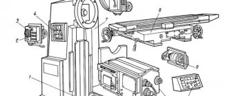
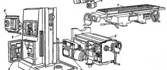
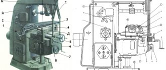
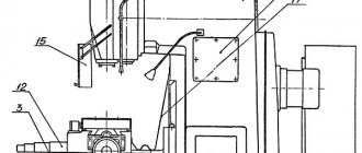
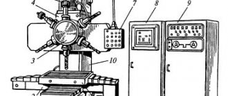
6A12p Location of components of a cantilever milling machine
Location of components of the 6A12p milling machine
List of components of the 6A12p cantilever milling machine
- feed switch handle;
- cross stroke end cams;
- block of electrical supports “Transverse”;
- block of electrical supports “Vertical”;
- remote control for dialing and reading programs;
- “Return drum to zero position” button;
- Spindle Jog button;
- gear shift handles;
- head rotation screw;
- quill clamp handle;
- quill movement handle;
- end cams of longitudinal stroke;
- block of electric supports “Longitudinal”;
- Remote Control;
- dial for transverse movement of the table;
- dial for vertical movement of the table;
- dial for longitudinal movement of the table;
- slide wedge adjustment screw;
- slide clamp handle.
Weight, dimensions and design
The 6M12P machine is distinguished by its rigid design, which allows it to produce complex parts with high precision - class H. Main dimensions of the unit:
- table 1250×320 mm;
- maximum workpiece weight 250 kg;
- dimensions 2395×1745×2000 mm;
- weight 3000 kg.
The greatest longitudinal movement of the table in mechanical mode is 700 mm.
The machine consists of standard components:
- base;
- bed;
- swivel head;
- console;
- sled and table;
- electrical equipment;
- gearbox;
- gearbox;
- switch box;
- gearbox.
The drive motor is mounted on a stand at the rear. The gearbox is in a hollow housing.
Design of individual components of the 6A12p cantilever milling machine
Bed and gearbox
Gearbox for console milling machine 6a12p
The bed is a hollow casting of a trapezoidal cross-section with a large number of ribs and mutually perpendicular walls, which gives it rigidity.
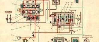
In the side niches of the frame, closed by doors, there are two panels of electrical equipment. To prevent oil and dirt from entering electrical equipment, the doors have a seal on the inside.
The gearbox is mounted in the bores of the frame (in its upper part). It has 18 speed levels. The required number of revolutions is set by switching three blocks of gears.
The electric motor shaft is connected through an elastic coupling to shaft 1 (Fig. 10) of the gearbox. From it, through a bevel gear with a circular tooth, the movement is transmitted to the milling head mounted on the V shaft.
When assembling the front shaft support V and tightening the bearings, the axial play of the shaft should not exceed 0.03-0.06 mm. Adjustment is made by grinding the rings located between the bearings. The engagement of the bevel wheels is adjusted by three screws in the front support cup.
Spindle braking is carried out by an electromagnetic clutch for 2-4 seconds. (Spindle braking in the 6A12R machine is electrodynamic.)
Gear shift mechanism
Speed switching mechanism of a 6a12p cantilever milling machine
The gear shift mechanism (Fig. 11) is a rocker mechanism with one handle. The movement of the scenes is carried out by a gear sector mechanism. The specified movements from the scenes are transmitted to the forks that switch the gearbox gear blocks.
The required number of spindle revolutions is set by rotating the handle in any direction, counting along the dial. To prevent spontaneous activation, the mechanism has a lock. In addition, an electrical locking with a microswitch is provided against the non-fixed position of the handle.
Milling head
Milling head of console milling machine 6a12p
The rotary milling head (Fig. 12) is a shaped cast iron casting, in the bores of which a movable quill 15, a spindle 13 and an intermediate shaft 2 with a gear drive are mounted. The front support of the spindle is a double-row radial roller bearing No. A3182118 with short cylindrical rollers. The rear support is two angular contact bearings No. A36214. The tension of the bearings of the rear spindle support is carried out by grinding the rings 9, and the bearing No. A3182118 - by grinding the half rings 12.
The spindle is unloaded. Axial and radial loads occurring on gear 6 are absorbed directly by the housing through the bearings. To adjust the engagement of the bevel gears, three screws 1 are provided.
The mechanism for moving the quill consists of a bracket with a nut 8, rigidly fixed to the quill, and a screw 7, which receives rotation from two bevel gears 10. One of the gears sits on the shaft together with the flywheel 11. When moving the quill, you must release the handle located on the left side of the milling machine. heads.
The milling head is rotated manually using a roller and gear mounted in the flange part of the frame.
Console
Console of milling machine 6a12p. (Vertical section)
Console of milling machine 6a12p. (Horizontal section)
The console is a cast-iron body with rectangular guides for the frame and guides perpendicular to them for the slide. Being a supporting bracket for the table and slide, the console simultaneously serves to accommodate mechanisms that transmit movement to longitudinal, transverse and vertical feeds, electric motors, feed boxes, a mechanism for lowering and raising the console, electromagnetic couplings, etc. The machine control panel is also mounted on the console.
There are three windows on the sides and top of the console (Fig. 13), through which the electromagnetic couplings are adjusted. On the right side of the console there is a window with a cover 8 for mounting the mechanism for lowering and raising the console. The lid 7 closes the niche in which there are terminal sets 6 with electrical wiring going to the electric couplings and electric motors. The front plane of the console is closed with cover 1, which serves as additional support for the feed shafts. Three feed dials are mounted on the lid: longitudinal, transverse and vertical (the division value of the dial is 0.05 mm, one revolution of the longitudinal and transverse feed dials corresponds to moving the table by 5 mm, the vertical feed dial by 2 mm).
To operate the machine manually, you need to: pull the dial, align its zero mark with the mark on the conical sleeve and then, by rotating the handle, move to the required milling size.
Inside the console there are three horizontal shafts: the longitudinal stroke of the table 11, the vertical stroke of the console 10 and the transverse stroke of the slide 9. At the ends of the shafts there are three cams for transmitting rotation from the manual control handles, which have a mechanical feed lock.
On each shaft there are two electromagnetic couplings 2, through which the console, table and slide move in the longitudinal, transverse and vertical directions. Reversal of movements occurs using electromagnetic couplings. From the middle shaft, through the bevel gear, the movement is transmitted to the vertical screw 3.
The vertical feed lead screw is supported by a nut 4 on a stand 5, which is rigidly attached to the base of the machine.
A ball safety clutch is attached to the vertical wall of the console, which engages with the VI shaft of the feed box. To adjust the clutch, it is necessary to remove cover 12 on the left side of the console and, through the window, use nuts to adjust the normal operation of the clutch. The adjustment will be correct if when milling cast iron (HB = 160..180) with an end mill Ø 110 mm, with the number of teeth 12, with a milling width of 80 mm, depth 6 mm, feed 500 mm/min, and spindle speed 1000 rpm , the clutch periodically clicks.
Gearbox
Feed box for milling machine 6a12p
The feed box of the 6A12P machine (Fig. 14) provides 18 workers, accelerated and slow feeds.
In the feed box of the 6A12R machine (Fig. 15) there is no feed slowdown unit. The feed switching mechanism is flanged to the feed box body.
Feed switching is carried out by triple blocks on the III and V shafts and a pick-up gear (z=40) on the V shaft. To switch the feed, the dial handle should be turned one turn.
Accelerated feed occurs when the electromagnetic clutch is turned on on the VI shaft of the feed knob.
When removing the feed box, special attention should be paid to the disassembly sequence. It is necessary to remove cover 12 on the left side of the console (Fig. 13), unscrew three screws in the safety clutch housing, and turn gear 13 toward the clutch so that the clutch can be removed through the window. After this, you can begin to remove the feed box. To facilitate its installation, it is recommended to remove filter 4 (Fig. 24), unscrew plug 5 and remove pump plunger 3, which prevents installation of the feed box in the console.
Console lowering and raising mechanism
The hydraulic mechanism for lowering and raising the console (Fig. 16) consists of a housing in which there is a piston-rack 2, clamps 3 and 4, a floating distributor 5 and an oil pump 1 driven by an electric motor.
Lowering the console when the mechanism is turned on occurs automatically at accelerated speed. When you turn on the accelerated speed from a button or cam (work according to the program), the oil pump motor turns on. Oil from cavity 4 is pumped into cavity B, having previously sunk the latch 4, to which rod 6 is rigidly connected. This rod acts on the block contact BK1, breaking the power circuit of the “Feed” clutch and preparing the power circuit of the console lowering starter (Fig. 17). The piston-rack 3 moves to the left until the latch 4, under the influence of the spring, enters the socket. In this case, the latch acts on the block contact BK2, the power supply to the starter of the console lowering mechanism is cut off, and the oil pump motor 1 is turned off.
When switching from rapid speed to feed or pressing the “Stop” button, the pump operates in reverse: oil is pumped into cavity A, moving piston 3 to the right; latch 4 presses the block contact BK-2, preparing the power circuit for the console lowering starters.
Moving to the right, the piston-rack opens channel 2, through which oil enters under lock 5 and moves it upward to a fixed position. The power circuit of the console lift starter is broken and the power supply circuit of the “Feed” clutch is created.
The piston-rack 3 rotates the gear sector, which is a bushing screw. The external threads of the screw provide support for the sleeve nut, rigidly fixed in the bore of the console body. The sector sits on a thrust ball bearing, which rests on the shoulder of the console lead screw. Rotating, it forces the nut and the console along with it to lower or rise by 1 mm, while the lead screw of the console remains motionless.
Table and slide
The table is the last element in the longitudinal feed chain. Thanks to the slide and console, the table is able to move transversely and vertically.
On the slide (Fig. 18) there is a handle for turning on the feed 7. If this handle is set to the “Circular feed” position, then there will be no longitudinal movements of the table; the splined shaft 32 rotates with the guitar drive gear 9, from which the movement is removed when installing a round table or dividing head with single and automatic continuous division.
In heavy power mode on longitudinal feed, the rigidity of the slide can be increased due to the handles 12 for clamping the slide on the console 10, which through the eccentric shaft 14 tighten the wedges 13. However, it is rarely necessary to use the handles, because under normal operating conditions the rigidity of the slide without clamping is sufficient . It is impossible to turn on the transverse stroke when the slide clamp handles are clamped, because the feed mechanism will work with a large overload.
Limiting cams of the longitudinal stroke 3 and 8 are designed to automatically turn off the longitudinal feed or longitudinal high speed, and limiting cams 11 are designed to turn off the transverse stroke. The movement of the end cams is limited by screws 2. It is prohibited to work on the machine without limit cams.
To set up the 6A12P machine according to the program, 5 cams are used, which are mounted in the grooves of the table, console and frame.
Screws 6 are designed to select play in the table bevels during heavy milling, if it is carried out for a short time along the length.
Mechanism for selecting backlash in a longitudinal screw-nut pair
The backlash selection mechanism consists of a housing 20 (Fig. 18, K - K), to the end of which a gear oil pump 27 is attached.
A double-acting piston runs in the cylinder of the mechanism body. The pressure in both cylinder cavities is regulated by valves.
A gear pump pumps oil into one of the cylinder cavities, causing the piston 26 to move with the rod 25. The piston rod is pivotally connected to an elongated lever 21, which rotates the axis 19. A shortened lever 18 sits on the axis, connected through a rod 1 to a fork 2 (Fig. 19 ). The fork directly acts on both half-nuts, with the help of which the play in the screw pair is selected.
The backlash selection mechanism is activated automatically when the machine is operating in down milling conditions (the toggle switch must be set to the “Climb milling” position). When the table moves to the right, the rotor of the mechanism's electric motor should rotate clockwise (if you look at the motor from the impeller side). On the 6A12R machine, play in the screw-nut pair as they wear is eliminated by tightening the half-nut.
Electromagnetic clutch
The multi-disc electromagnetic clutch is designed to transmit torque of 5-7.5 kg. m. The electromagnet winding is designed for a voltage of 24 V and a power of 13.7 W; the wire of the PEV-1 winding has a diameter of 0.44 mm and the number of turns is 1360. The coupling (Fig. 20) consists of an electromagnet 1, an armature 3 > disks, an adjusting nut 4, a pressure disc spring 7 and springs that release the disks after the clutch de-energized.
The armature and yoke of the electromagnet are made of Armco iron. Internal friction discs 6 are made of steel, outer friction discs 5 are made of steel with a metal-ceramic lining.
Power is supplied to the clutch electromagnet through the brush holder. The magnetic flux created by the coil located on the yoke, closing through the armature, attracts it to the electromagnet. The armature is connected through three screws to a crosspiece, which, through a disc spring, compresses the outer and inner friction discs that transmit torque.
As the metal-ceramic lining wears out, it is necessary to adjust the coupling when it is de-energized. To do this, you need to press the bar 8 with the lock 9 towards the anchor and turn it 30-45° to the left or right from the radial position. Then turn the adjusting nut counterclockwise (if you look at it from the side of the disks) by 3-4 steps corresponding to the entry holes of the clamp 9 and disk 10, place the bar 8 in the radial position and slightly rotate the nut 4 to the left and right, lock it with the clamp 9. Turn on coupling and see if anchor 3 is adjacent to the yoke along the entire circumference; if not, then you should loosen the nut by 1-2 steps of the clamp.
The electromagnetic clutch can operate in both oil and air environments.
Electrical stop block
The block of electrical supports of the 6A12P machine (Fig. 21) consists of a housing 2, inside of which ten microswitches 1 are mounted (eight of them are designed to operate according to the program). Two microswitches are final: one “Stop” - for moving the table, for example, to the left - is indicated by the icon 0 -, the other “Stop” - for moving the table to the right - is indicated - 0. The designations of all microswitches are marked on the removable cover 8.
The electric stop block works as follows: when the cam is pressed on the movable stop 3, the movement is transmitted through the adjusting screw 4 to the spring lever 5, which directly acts on the microswitch. The response time of the microswitch when moving the movable stop 3 depends on the setting of the adjusting screw 4. In the case of a large stop stroke by lever 5, a pinch is created in the block. All ten spring levers sit freely on axis 6. The block of electric stops is hermetically sealed, each stop has a protective rubber cap 7.
Specifications
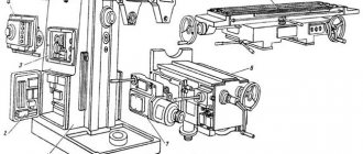
Component Location
To become familiar with the operational and performance characteristics of the 6P12 machine, it is necessary to study the equipment passport in detail. Since this model belongs to the professional category, before performing milling, the worker must undergo safety training and become thoroughly familiar with the operating principle of the elements and assemblies.
The weight of the machine with all installed equipment is 3120 kg. Its dimensions do not exceed 228*196.5*226.5 cm. When compared with similar models, you will notice that the dimensions of the machine are larger than standard. This must be taken into account when choosing an installation location.
The main technical characteristics of the 6P12 model are indicated in detail in the passport. But to select the correct operating mode, you should know the following machine parameters:
- desktop dimensions – 125*32 cm;
- the maximum permissible weight of the workpiece being processed is 250 kg;
- desktop progress. In the longitudinal direction – up to 80 cm; in transverse – 25 cm;
- maximum vertical displacement of the table surface – up to 42 cm;
- the nominal speed of the spindle head varies from 40 to 2000 rpm;
- number of spindle speeds – 18;
- the spindle quill can change its position by 70 mm;
- the number of table feeds is the same for all directions (longitudinal, transverse and vertical) and is 22.
The power of the electric motor of the main spindle drive is 7.5 kW. To activate the high-speed clutch of the working table, the 6р12 vertical milling machine has in its design special gears connected to the power plant shaft.
Cooling system
Cooling is recommended when working with high-speed cutters on steel. It not only reduces the heating of the cutting blades of the tool, but also improves the conditions for cutting metal.
The amount of emulsion supplied is regulated by a tap, which can also be used as an emulsion switch tap. Emulsions are also used as coolants.
Along the side groove of the table (Fig. 18, B - C), the emulsion flows downhill through filter 28, passes through meshes 29 and 30 and through tube 31 enters the sled groove, made with a slope. Next, through the nipple and hose, the liquid enters the console. As chips accumulate in filter 28, it should be cleaned.
Purpose of the machine
The series of machines has various modifications, but many characteristics within the model range remain the same. 6M12P is an improved version of the N series.
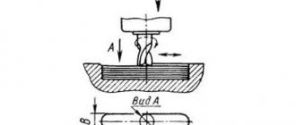
Thanks to the use of such devices, you can perform a large number of operations:
- Milling of various parts based on materials such as non-ferrous and ferrous metals, cast iron and steel. The shape can be any - radius and end, cylindrical, end.
- Support for automatic and semi-automatic cycles. Thanks to this, the machines become indispensable assistants when performing work with an operational nature, with fully automated lines.
- The machines allow you to process horizontal and vertical surfaces, grooves and corners.
- Milling can be counter or down milling.
- High-speed milling is a processing method that makes equipment especially efficient.
Lubrication system
Timely lubrication protects the machine from wear and maintains its original accuracy for a longer period.
Industrial oil “20” (spindle “3”), GOST 1707-51, is used to lubricate the machine.
Before starting the machine, tanks with plugs 2, 9, 10 and 12 (Fig. 22) are filled with oil to the level determined by the upper holes of the corresponding oil indicators 3, 4 and 11. The oil level is not allowed to fall below the lower holes of the oil indicators.
Main drive lubrication
Gears and bearings are lubricated by a plunger oil pump, driven by end cam 2 (Fig. 23). The pump is located in the bore of the frame and is secured with four screws. When installing the pump, it is necessary to ensure the tightness of the connection of the pipeline to the oil pump so that there is no air suction through the gaps into the oil pipeline system.
The pump plunger forces the oil into the oil distributor 1 and goes through the tubes to the lubrication points. The oil distributor has adjusting screws, with the help of which the oil supply to one or another lubrication point of the machine is regulated.
Lubricant is supplied to the milling head by vinyl chloride hose 4 (Fig. 12), which is connected to fitting 3 on the upper flange of the milling head housing. As a result of adjustment by screw 5, a droplet supply of oil is achieved to the bearings of the front and rear spindle supports. The adjustment is considered correct if within 40..60 seconds. one drop is served.
During continuous operation of the machine, oil collects in flange 14. To remove excess oil, the flange has a drain hole. The operation of the oil pump can be judged by the oil indicator on the milling head.
Console and feed box lubrication
The console is lubricated (Fig. 24) by forced lubrication from plunger pump 1, flanged to the bottom of the console. The pump sucks oil through filter mesh 4 and supplies it to oil distributor 2, located on the right side of the console. The operation of the oil pump can be judged by the pulsation of oil in the oil distributor.
The amount of oil supplied to the tube is regulated using the oil distributor screws.
The oil pressure in the lubrication system is adjusted using a control valve.
Lubricating the vertical console screw
In the lower part of the frame there is an oil bath designed to lubricate the vertical stroke screw of the console. The oil level when filling is determined by oil filling hole 10 (Fig. 22). Filling is carried out until oil begins to pour out of this hole. The console must be lowered when filling oil.
Slide lubrication
The slide is lubricated by gear pump 27 of the backlash selection mechanism (Fig. 18).
When you press button 4, the pump starts operating, supplying oil to the distributor, from which it flows to the lubrication points.
The indicator for the start of oil supply is the jet oil distributor 1. After 4..5 seconds. After oil appears in the oil indicator, button 4 should be released. The slides must be lubricated twice per shift.
Vertical milling machine mod. 6T12, 6T13 (analogous to 6P12, 6P13, VM127M).
DESIGN FEATURES OF MACHINE 6T-12, 6T-13.
- Availability of various automatic milling cycles.
- Automated lubrication of components.
- Automated tool mounting in the spindle.
- Availability of a mechanism for proportional feed slowdown.
- Electromagnetic clutches for controlling coordinate switching.
- The presence of a gap limiting device in the longitudinal stroke screw pair.
- Mechanical safety clutch for feed drive protection.
- Electromagnetic clutch brakes the spindle when stopping.
TECHNICAL CHARACTERISTICS OF THE CONSOLE MILLING MACHINE:
| Vertical milling console machine mod. 6T12, 6T13 are widely used in various modern metalworking industries to perform a variety of milling operations using cylindrical, angular, shaped, face and other cutters; when processing horizontal, vertical planes, grooves, frames, corners, gears, stamp models, molds and other parts made of steel, cast iron, non-ferrous metals and their alloys. | ||
| 6T12 | 6T13 | |
| Spindle end, GOST 24644-81 | 50, 40 | 50, 40 |
| Maximum permissible diameter of cutters, mm spindle of rotary head | 160 | 200 |
| Dimensions of the working surface of the table, mm width length | 3201250 | 4001600 |
| Maximum table movement, mm longitudinal transverse vertical | 800320420 | 1010400430 |
| Number of T-slots | 3 | 3 |
| Number of rotational speeds of the spindle of the rotary head | 18 | 18 |
| Spindle speed limits, rpm. rotary head | 31,5…1600 | 31,5…1600 |
| Number of table feeds | 22 | 22 |
| Table feed limits, mm/min. longitudinal and transverse vertical | 12,5…16004,1…530 | 12,5…16004,1…530 |
| Speed of rapid table movement, mm/min. longitudinal transverse | 40001330 | 40001330 |
| Proportional slow feed, mm/min. | 1/2S | 1/2S |
| Electric motor power, kW main feed movement | 7,53 | 113 |
| Machine dimensions, mm length width height | 228019652265 | 257022522430 |
| Machine weight, kg | 3200 | 4250 |
Contents of delivery:
| Designation | Name | 6Т12-29 | 6Т13-29 |
| Complete machine | 1 | 1 | |
| Included in the kit and the cost of the machine | |||
| Dismantled parts | |||
| Protective device | 1 | 1 | |
| Cutting area guard | 1 | 1 | |
| Valve with nozzle | 1 | 1 | |
| Manual movement handle | 1 | 1 | |
| Handwheel | 1 | 1 | |
| Table shield | 2 | 2 | |
| Lamp NKSO1x100/P20-01U4 | 1 | 1 | |
| Lamp MO24-40U3 | 1 | 1 | |
| Rear casing | 1 | 1 | |
| Accessories and tools | |||
| 6T82G.880.254 | Key to electrical cabinet | 1 | 1 |
| 6222-0134 | Mandrel | 1 | 1 |
| 6Р12К.93.100/42А | Capture | 1 | 1 |
| 24.65G.05 | Washer GOST 6402-70 | 1 | 1 |
| 6Р12К.93.100/41А | Capture | 1 | 1 |
| 191.831.055 | Transitional sleeve | 1 | 1 |
| Documentation | |||
| 6T12-29.000.000 RE | Manual. Part I | 1 | 1 |
| 6T82G-29.000.000 RE1 | Manual. Part II. | 1 | 1 |
| 6T82G-29.000.000RE2 | Information about acceptance, preservation, packaging. Part III. | 1 | 1 |
Technical characteristics of the cantilever milling machine 6A12p
| Parameter name | 6A12p | 6N12 | 6M12 | 6Р12 | 6T12 |
| Basic machine parameters | |||||
| Accuracy class according to GOST 8-71 and GOST 8-82 | N | N | N | N | |
| Table surface dimensions, mm | 1250 x 320 | 1250 x 320 | 1250 x 320 | 1250 x 320 | 1250 x 320 |
| Maximum mass of the workpiece, kg | 250 | 250 | 400 | ||
| Distance from the end of the spindle to the table, mm | 435 | 30..400 | 30..400 | 30..450 | 30..450 |
| Distance from the spindle axis to the vertical guides of the bed (overhang), mm | 320 | 350 | 350 | 350 | 380 |
| Desktop | |||||
| Maximum longitudinal travel of the table by hand (along the X axis), mm | 760 | 700 | 700 | 800 | 800 |
| Maximum lateral movement of the table by hand (along the Y axis), mm | 260 | 240/ 260 | 240/ 260 | 250 | 320 |
| Maximum vertical travel of the table by hand (along the Z axis), mm | 400 | 370 | 370 | 420 | 420 |
| Movement of the table by one division of the dial in the longitudinal and transverse directions, mm | 0,05 | ||||
| Moving the table one division of the dial in the vertical direction, mm | 0,02 | ||||
| Movement of the table per one revolution of the dial in the longitudinal and transverse directions, mm | 5 | ||||
| Moving the table one revolution of the dial in the vertical direction, mm | 2 | ||||
| Limits of longitudinal table feeds (X), mm/min | 20..1000 | 40..2000 | 12..1250 | 12,5..1600 | 12,5..1600 |
| Limits of table cross feeds (Y), mm/min | 20..1000 | 27..1330 | 12..1250 | 12,5..1600 | 12,5..1600 |
| Limits of vertical table feeds (Z), mm/min | 8..400 | 13..665 | 8,3..416,6 | 4,1..530 | 4,1..530 |
| Number of feeds longitudinal/transverse/vertical | 18 | 18 | 18 | 22 | 22 |
| Speed of fast longitudinal movements of the table (along the X axis), m/min | 2,5 | 4 | 3 | 4 | 4 |
| Speed of fast transverse movements of the table (along the Y axis), m/min | 2,5 | 4 | 3 | 4 | 4 |
| Speed of fast vertical movements of the table (along the Z axis), m/min | 1 | 1 | 1 | 1,330 | 1,330 |
| Slow feed, mm/min | 20/20/8 | — | — | — | — |
| Spindle | |||||
| Spindle speed, rpm | 40..2000 | 63..3150 | 31,5..1600 | 40..2000 | 31,5..1600 |
| Number of spindle speeds | 18 | 18 | 18 | 18 | |
| Spindle quill movement, mm | 50 | 70 | 70 | 70 | 70 |
| Milling spindle taper | №3 | №3 | №3 | №3 | №3 |
| Spindle end GOST 24644-81, row 4, version 6 | GOST 836-62 | 50 | |||
| Milling spindle hole, mm | 27 | 29 | 29 | 29 | |
| Rotate the spindle head right and left, degrees | ±45° | ±45° | ±45° | ±45° | ±45° |
| Machine mechanics | |||||
| Feed stops (longitudinal, transverse, vertical) | Eat | Eat | Eat | Eat | Eat |
| Blocking manual and mechanical feeds (longitudinal, transverse, vertical) | Eat | Eat | Eat | Eat | Eat |
| Blocking separate feed switching | Eat | Eat | Eat | Eat | Eat |
| Spindle braking | Eat | Eat | Eat | Eat | Eat |
| Overload safety clutch | Eat | Eat | Eat | Eat | |
| Automatic intermittent feed | Eat | Eat | Eat | Eat | |
| Electrical equipment, drive | |||||
| Number of electric motors on the machine | 3 | 3 | 3 | 4 | |
| Main motion drive electric motor, kW (rpm) | 5,5 (1400) | 7 | 7,5 | 7,5 | 7,5 |
| Feed drive electric motor, kW (rpm) | 1,1 (1400) | 1,7 | 2,2 | 2,2 | 3,0 |
| Tool clamping motor, kW (rpm) | — | — | — | — | 0,25 |
| Electric motor of the pump for lowering and raising the console, kW (rpm) | 0,12 (1400) | — | — | — | — |
| Electric motor of the backlash selection mechanism pump, kW (rpm) | 0,12 (1400) | — | — | — | — |
| Coolant pump electric motor, kW (rpm) | 0,12 | 0,12 | 0,12 | 0,12 | 0,12 |
| Total power of all electric motors, kW | 9,825 | 9,825 | 1,87 | ||
| Dimensions and weight of the machine | |||||
| Machine dimensions (length width height), mm | 1765 x 2375 x 1950 | 1745 x 2260 x 2000 | 2395 x 1745 x 2000 | 2305 x 1950 x 2020 | 2280 x 1965 x 2265 |
| Machine weight, kg | 2500 | 3000 | 3000 | 3120 | 3250 |
- Manually controlled desktop milling machine model MS-51. Manual. Lugansk Machine Tool Plant named after. Lenina, 1992
- Avrutin S.V. Fundamentals of Milling, 1962
- Avrutin S.V. Milling, 1963
- Acherkan N.S. Metal-cutting machines, Volume 1, 1965
- Barbashov F.A. Milling business 1973, p.141
- Barbashov F.A. Milling work (Vocational education), 1986
- Blumberg V.A. Milling machine handbook, 1984
- Grigoriev S.P. Practice of coordinate boring and milling work, 1980
- Kopylov R.B. Working on milling machines, 1971
- Kosovsky V.L. Handbook of a young milling operator, 1992, p. 180
- Kuvshinsky V.V. Milling, 1977
- Nichkov A.G. Milling machines (Machinist's Library), 1977
- Pikus M.Yu. A mechanic's guide to repairing metal-cutting machines, 1987
- Plotitsyn V.G. Calculations of settings and adjustments of milling machines, 1969
- Plotitsyn V.G. Setting up milling machines, 1975
- Ryabov S.A. Modern milling machines and their equipment, 2006
- Skhirtladze A.G., Novikov V.Yu. Technological equipment for machine-building industries, 1980
- Tepinkichiev V.K. Metal cutting machines, 1973
- Chernov N.N. Metal cutting machines, 1988
- Frenkel S.Sh. Handbook of a young milling operator (3rd ed.) (Vocational education), 1978
Bibliography:
Related Links. Additional Information
- Milling machines: general information, classification, designation
- Comparative characteristics of cantilever milling machines of the 6N, 6M, 6R, 6T
- Feed box for console milling machines of the 6M : 6M12P, 6M13P, 6M82, 6M83, 6M82Sh, 6M83Sh
- Feed box for console-milling machines of the 6P : 6Р12, 6Р13, 6Р82, 6Р83, 6Р82Ш, 6Р83Ш Feed box for console-milling machines of the 6Т : 6T12, 6T13, 6T82, 6T83, 6Т82Ш, 6Т83Ш
Electrical equipment of milling machines of the Gorky Machine Tool Plant, GZFS
Electrical equipment of milling machines of the Vilnius Zalgiris Machine Tool Plant
Vertical milling machine 6Р13, 6Т13, 6М13П, 6Н13П, 6Н13 today
Vertical milling machines 6Р13, 6Т13, 6М13П, 6Н13П, 6Н13 were produced at several enterprises of the former USSR. Currently, most of these enterprises no longer exist. At the same time, leading machine tool factories switched to the production of machines of a more modern design, focused on modern tools and high cutting speeds. Such machines are equipped with modern high-quality components and reliable electrical equipment. Thanks to the use of computer-aided design of beds, an increased accuracy class for a milling machine manufactured at a modern plant is rather the rule today. At the same time, prices for modern machines are quite comparable with prices for machines of outdated design.
Feed box for vertical milling machine models 6р12,6р13
Using the feed box, working and accelerated feeding of the table, slide and console is carried out. The torque is transmitted to the output shaft 36 through the overload and cam clutch 46 and the sleeve 45. The sleeve 45 connects the cam clutch 46 and the output shaft 36 using a key connection.
Accelerated rotational motion is transmitted from the electric motor, bypassing the feed box and gear 37, which is located on the shank of the clutch housing 51 and has a constant rotation speed.
Console of vertical milling machine models 6р12,6р13
The console is the main unit that unites the nodes of the machine feed chain. The console consists of shafts and gears that transmit rotational motion in three directions - to the longitudinal, transverse and vertical feed screws, as well as a transverse and vertical feed mechanism.
Gear 71 receives rotational motion from gear 34 and transmits it to gears 64, 65, 67 and 70. Gear 67 transmits torque to the shaft only through dog clutch 69. Then, through several gears, the movement is transmitted to screw 77.
The bevel gear 73 and 78 is adjusted by compensators 75 and 76 and fixed with a screw.
Gear 65 sits on a keyed connection on the sleeve and the splines constantly rotate from the longitudinal shaft 9.
The passport for the vertical milling machine can be downloaded here
Technical characteristics of vertical milling machine 6Р12,6Р13
| Main settings | 6Р12 | 6Р13 |
| Dimensions of the working surface of the table, mm | 1250x320 | 1600x400 |
| Maximum table movement, mm: | ||
| longitudinal mechanical | 800 | 1000 |
| longitudinal manual | 800 | 1000 |
| transverse mechanical | 240 | 320 |
| transverse manual | 250 | 300 |
| vertical mechanical | 410 | 410 |
| vertical manual | 420 | 420 |
| The smallest and greatest distance from spindle end to table, mm | 30-450 | 30-500 |
| Distance from spindle axis to vertical bed guides, mm | 350 | 420 |
| Moving the table per division of the dial, mm | 0,05 | 0,05 |
| Maximum axial movement of the spindle quill, mm | 70 | 80 |
| Machine dimensions: | ||
| length | 2305 | 2560 |
| width | 1950 | 2260 |
| height | 2020 | 2120 |
| Machine weight, kg | 3120 | 4200 |
https://youtube.com/watch?v=jMRw9VRPXcA
This is interesting: Mandrel pipe benders - do-it-yourself manufacturing, operating principle