Information about the manufacturer of the 6T13 cantilever milling machine
The manufacturer of the 6T13 series of universal milling machines is the Gorky Milling Machine Plant , founded in 1931.
The plant specializes in the production of a wide range of universal milling machines, as well as milling machines with DRO and CNC, and is one of the most famous machine-tool enterprises in Russia.
Since 1932, the Gorky Milling Machine Plant has been producing machine tools and is an expert in the development and production of various metal-cutting equipment.
Universal milling machines of the T series have been produced by the Gorky Milling Machine Plant (GZFS) since 1985. The machines are similar in design, widely unified and are a further improvement of similar machines of the P series (6P12, 6P13).
Today the 6T13 cantilever milling machine produces:
- Stanochny Park LLC;
- LLC SO "PRESSMASH";
- Machine tool association LLC SO "StanRos".
Products of the Gorky Milling Machine Plant GZFS
- 6M12P
vertical cantilever milling machine 320 x 1250 - 6M13P
vertical cantilever milling machine 400 x 1600 - 6M82
universal horizontal milling machine 320 x 1250 - 6M83
universal horizontal milling machine 400 x 1600 - 6M82G
horizontal cantilever milling machine 320 x 1250 - 6M83G
horizontal cantilever milling machine 400 x 1600 - 6М82Ш
universal cantilever milling machine 320 x 1250 - 6N12
vertical cantilever milling machine 320 x 1250 - 6N13P
vertical cantilever milling machine 400 x 1600 - 6N82
horizontal cantilever milling machine 320 x 1250 - 6N82G
horizontal cantilever milling machine 320 x 1250 - 6Р12, 6Р12Б
vertical cantilever milling machine 320 x 1250 - 6Р13, 6Р13Б
vertical cantilever milling machine 400 x 1600 - 6Р13Ф3
vertical cantilever milling machine with CNC 400 x 1600 - 6Р82
universal horizontal milling machine 320 x 1250 - 6R82G
horizontal cantilever milling machine 320 x 1250 - 6Р82Ш
universal cantilever milling machine 320 x 1250 - 6Р83
universal horizontal milling machine 400 x 1600 - 6R83G
horizontal cantilever milling machine 400 x 1600 - 6Р83Ш
universal cantilever milling machine 400 x 1600 - 6T12-1
vertical cantilever milling machine 320 x 1250 - 6T12
vertical cantilever milling machine vertical 320 x 1250 - 6T12F20
vertical cantilever milling machine with CNC 320 x 1250 - 6T13
vertical cantilever milling machine 400 x 1600 - 6T13F20
vertical cantilever milling machine with CNC 400 x 1600 - 6T13F3
vertical cantilever milling machine with CNC 400 x 1600 - 6T82
universal horizontal milling machine 320 x 1250 - 6T82-1
universal horizontal milling machine 320 x 1250 - 6T82G
horizontal cantilever milling machine 320 x 1250 - 6Т82Ш
universal cantilever milling machine 320 x 1250 - 6T83
universal horizontal milling machine 400 x 1600 - 6T83-1
universal horizontal milling machine 400 x 1600 - 6T83G
universal horizontal milling machine 400 x 1600 - 6Т83Ш
universal cantilever milling machine 400 x 1600 - 6606
longitudinal milling machine 630 x 2000 - GF2171
vertical milling machine with CNC and ASI 400 x 1600
Terms of purchase
To buy a ready-made CNC milling machine 6T13F3/6R13F3 or find out the price for repairs, please contact us by phone +7 (4852) 66-40-25 , by email: This email address is being protected from spambots. You must have JavaScript enabled to view it. or through the feedback form on the website. Production time and price depend on the configuration and execution of the machine. We provide a guarantee of 12 - 18 months. Under an additional agreement, we carry out transportation and commissioning work at the customer’s premises.
6T13 vertical cantilever milling machine. Purpose and scope
The vertical cantilever milling machine 6T13 is designed on the basis of the basic model 6T13-1
with a high degree of unification of functional units and parts.
6T13 vertical cantilever milling machine is designed for milling all kinds of parts from various materials. It is used in single and serial production.
The 6T13 cantilever milling machine differs from the 6T12 machine in the installed power of the main movement and feed motors, the dimensions of the working surface of the table and the amount of table movement.
6T13 machine can process vertical and horizontal planes, grooves, corners, frames, gears, etc.
The vertical console milling machine 6T13 can operate in three modes:
- Automatic - In automatic mode, the machine operates at various automatic cycles.
- Jog — In jog mode, adjustment movements of the table are made. Marking work is possible.
- Manual - In the manual universal mode, the machine operates using working feeds, rapid movements, as well as manual movements from the flywheels and handle.
Design features of the 6T13 milling machine
The technological capabilities of machines can be expanded through the use of overhead milling, dividing and slotting heads, and a round rotary table.
There is a device for limiting the gap in the screw pair for the longitudinal movement of the table, individual lubrication of the vertical movement screw, which increases its durability and reduces the lifting force of the console.
Additional devices have been introduced to protect against flying chips and emulsions .
The rigidity of the machine has been increased due to the rectangular guides of the bed and console.
There is automatic spindle braking in operating mode and during emergency shutdown.
Automated lubrication of components increases their durability and reduces maintenance time.
The machine table can be rotated around a vertical axis by ±45° , which makes it possible to mill various helical spirals using dividing devices.
The rotating spindle head of the machine is equipped with a mechanism for manual axial movement of the spindle sleeve, which allows processing of holes whose axis is located at an angle of up to ±45° to the working surface of the table.
The drive power and high rigidity of the machines allow the use of cutters made of high-speed steel, as well as tools equipped with plates made of hard and super-hard synthetic materials.
Tool fastening is mechanized . The cross-feed screw is located along the axis of the cutter, which increases processing accuracy. The technological capabilities of the machine can be expanded with the use of a dividing head, a rotary round table and other devices.
The ability to configure the machine for various semi-automatic and automatic cycles allows you to organize multi-machine maintenance and use the machine to perform various jobs in continuous production.
6T13 machine can be supplied to countries with temperate, cold and tropical climates.
Machine accuracy class - N according to GOST 8-82E
The main design advantages of the machines:
- mechanized tool fastening in the spindle;
- proportional feed deceleration mechanism;
- a device for periodically adjusting the size of the gap in the longitudinal feed screw pair;
- safety clutch protecting the feed drive from overloads;
- braking of the horizontal spindle when stopping using an electromagnetic clutch;
- protection device against flying chips.
Main technological advantages of the machines:
- various automatic machine operation cycles;
- wide range of spindle speeds and table feeds;
- high drive power;
- high rigidity;
- reliability and durability.
- The technological capabilities of machine tools can be expanded by using a dividing head, a round rotary table and other devices.
The machines are produced in various versions according to voltage and frequency of the supply network. Spare parts are supplied.
Modifications of console-milling machines of the “T” series
Various modifications and specialized machines have been developed based on the “T” series machines:
- 6T12 - 6T12-27, 6T12-29, 6T12-30
- 6Т13 - 6Т13-27, 6Т13-29, 6Т13-30
- 6T82G - 6T82G-27 (GF2793), 6T82G-29, 6T82G-30
- 6T83G - 6T83G-27 (GF2797), 6T83G-29, 6T83G-30
- 6T82 - 6T82-27 (GF2794), 6T82-29, 6T82-30
- 6T83 - 6T83-27 (GF2798), 6T83-29, 6T83-30
- 6T82Sh - 6T82Sh-27, 6T82Sh-29, 6T82Sh-30, 6T82Sh-35, 6T82Sh-36, 6T82Sh-37, 6T82Sh-38
- 6T83Sh - 6T83Sh-27, 6T83Sh-29, 6T83Sh-30, 6T83Sh-35, 6T83Sh-36, 6T83Sh-37, 6T83Sh-38
Modifications 6T...-27 have a 100 mm increased distance from the spindle axis (end) to the working surface of the table and a mechanism for proportional (2 times) slowdown of the working feed.
Russian and foreign analogues of the 6T12 (6T13) machine
FSS350MR, FSS450MR - 315 x 1250, 400 x 1250 - manufacturer Gomel Machine-Tool Plant
VM127M - (400 x 1600) - manufacturer Votkinsk Machine-Building Plant GPO, Federal State Unitary Enterprise
6D12, 6K12 - 320 x 1250 - manufacturer Dmitrov milling machine plant DZFS
X5032, X5040 - 320 x 1320 - manufacturer Shandong Weida Heavy Industries, China
FV321M, (FV401) - 320 x 1350 (400 x 1600) - manufacturer Arsenal JSCo. — Kazanlak, Arsenal AD, Bulgaria
History of production of machine tools by the Gorky plant, GZFS
In 1937
, the Gorky
Milling Machine Plant produced the first cantilever milling machines of the 6B series, models 6B12 and 6B82 , with a work table of 320 x 1250 mm (2nd standard size).
In 1951
6N of cantilever milling machines was launched into production 6N13PR machine received the “Grand Prix” at the world exhibition in Brussels in 1956.
In 1960
6M cantilever milling machines
was launched into production In 1972
6P of cantilever milling machines
was put into production In 1975
year, copying cantilever-milling machines were launched into production:
6Р13К .
In 1978
In 2009, copying cantilever-milling machines
6Р12К-1 , 6Р82К-1 .
In 1985
6T-1 of cantilever milling machines
was put into production In 1991
6T of cantilever milling machines was put into production
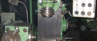
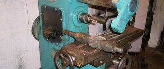
General view of the vertical cantilever milling machine 6T13
Photo of the 6T13 cantilever milling machine
Photo of the 6T13 cantilever milling machine
Operation and repair, passport
The mechanism itself requires installation on a concrete foundation with a thickness of at least 30 cm. In this case, the surface must be perfectly flat. This will reduce the risk of inaccuracies during fine milling.
During initial start-up, be sure to fill the lubrication system reservoir with oil. Once a year you need to flush the oil reservoir. In case of any malfunction, the machine should be turned off and a technician should inspect it. Any part in the machine must be replaced when worn out, so the unit itself does not have a service life.
The passport of the milling machine can be downloaded for free from the link – Passport of the vertical console milling machine 6T13.
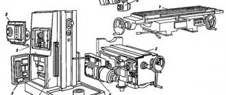
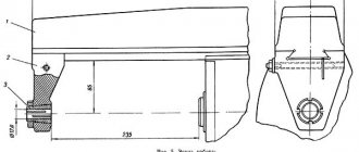
Arrangement of components of the 6T13 cantilever milling machine
Location of components of the 6T13 milling machine
List of components of the 6T13 cantilever milling machine
- bed
- side remote control
- feed switch mechanism
- spindle gearbox
- rotating head
- electromechanical tool clamping devices
- control cabinet
- table and sled
- feed delay mechanism
- main remote control
- console
- gearbox
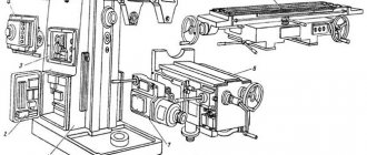
Location of controls for the 6T13 cantilever milling machine
Location of controls for the 6T12 milling machine
Control panels for milling machine 6T13
Control panels for milling machine 6T13: main -II, side -I
List of controls for the 6T13 cantilever milling machine
- Spindle speed indicator
- Button “Move table back, forward, down”
- Switch for selecting the direction of table movement
- Switch “Clamp-Release Tool”
- Button “Move table forward, left, up”
- Spindle Jog button (duplicate)
- Button “Stop table movement”
- Spindle start button
- “Spindle Stop” button (duplicate)
- Emergency Stop button
- Button “Fast table movement” (duplicate)
- Spindle speed shift knob
- —
- Hexagon head rotation
- Spindle sleeve clamp handle
- Key "Move table left"
- "Move table to the right" key
- Key "Stop longitudinal movement of the table"
- Spindle Stop button
- Spindle start button
- Table Clamps
- Switch for switching on the table operating mode “Manual - Mechanical”
- Flywheel for manual longitudinal movement of the table
- Vernier ring
- Limb of the table transverse movement mechanism
- Manual lateral movement of the table
- Manual vertical table movement
- Feed switch mushroom
- Emergency Stop button
- Machine operating mode selection switch
- Slow feed switch
- Button “Fast table movement and cycle start”
- “Stop vertical table movement” key
- "Move table down" key
- Slide Clamps
- "Move table up" key
- Flywheel for manual longitudinal movement of the table (duplicate)
- Key "Stop lateral movement of the table"
- "Move table forward" key
- "Move table back" key
- Spindle sleeve extension flywheel
- Clamping the head on the frame
- Input switch
- Spindle rotation direction switch “Left - Right”
- Cooling pump switch "On - Off"
- Control panel selection switch
- Auto cycle selection switch
- Console Clamp
- Removable handle for manual vertical and transverse movement of the table
- Zero head fixation pin
General appearance and design
The unit is distinguished by the adhesion strength of individual components and their independent control. The cast base gives the machine stability. The ability to fine tune gives the ability to mill small parts.
Location and description of components
Main design elements:
- Bed. Wide rectangular platform on pins with a vertical neck.
- Spindle head and sleeve. A rotary mechanism fixed in the annular recess of the frame, with a motor for clamping the cutting part.
- Control cabinet. Includes an electric drive for spindle movement, a gearbox, a control panel and several separate switches.
- Front console. Table guide motor and devices for regulating their movement.
The weight of the assembled machine is 4300 kg, height 2430 mm, width 2252 mm. Total length 2570 mm. The travel of the working surface is up to 1 m from right to left, up to 40 cm in the transverse plane and up to 43 cm in the vertical.
Location of controls
The main movement is controlled by a gearbox, which includes 18 spindle speeds. Adjustable using a handle with corresponding divisions. The position of the head is ensured by a rotary hexagon and a flywheel for mechanical extension of the sleeve. A separate handle is provided for clamping the sleeve.
The feed drive controls table movements through normal and high speed clutches. When you select one of these modes, the other is blocked. The drive box allows for 18 different feeds. For precise preliminary positioning of the workpieces, mechanical clamps of the table and console slides are provided on the frame guides. Each working element is equipped with a manual flywheel.
https://youtube.com/watch?v=N0wcKDsBE3Q
Control panels
The 6T13 machine has two operator consoles - a side one on the wall of the control cabinet, and a main one on the table console. As well as a panel for selecting automatic cycles. The speed and direction of feeds are regulated from the main one, the movement of the spindle head from the side. Buttons for basic actions - start, stop, enabling fast movement mode or slow feeds - are duplicated on both panels.
The key for turning on the machine, as well as changing the direction of rotation of the cutter, is located on the rear wall of the device. But there is an emergency shutdown button on the main remote control. It also switches the cooling mode on and off. The remote control is selected using a switch on the side.
Features of the structure of the rotary head
The mechanism for rotating the spindle is a system of conical rings, half rings and gears, and is attached to the frame flange with bolts. Guide sleeves are fixed to the rotating head, inside which there is a double-support spindle shaft on bearings. In the upper part of the sleeve there is a drive for the cutting tool clamp. To avoid injury, spindle rotation is blocked without first fixing the cutter.
If necessary, the head design allows you to adjust the axial and radial play of rotation. For this purpose, there is a removable plug on its body. Through this hole, the size of the play between the bearing and the spindle cylinder is measured. The adjustment is carried out by grinding the axial and radial half rings.
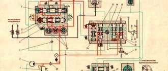
Kinematic diagram of the 6T13 cantilever milling machine
Kinematic diagram of the 6T13 cantilever milling machine
The kinematic diagram is given to understand the connections and interactions of the main elements of the machine. The numbers of teeth (g) of the gears are indicated on the callouts (the asterisk indicates the number of starts of the worm).
The main movement is driven by a flange electric motor through an elastic coupling.
The spindle speed is changed by moving three toothed blocks along the splined shafts.
The gearbox provides the spindle with 18 different speeds.
The feed drive is carried out from a flange electric motor mounted in the console. By means of two three-crown blocks and a movable gear wheel with a cam clutch, the feed box provides 18 different feeds, which are transmitted through a ball safety clutch to the console and then, when the corresponding cam clutch is engaged, to the screws of longitudinal, transverse and vertical movements.
Accelerated movements are obtained when the high-speed clutch is turned on, the rotation of which is carried out through intermediate gears directly from the feed electric motor.
The clutch is interlocked with the working feed clutch, which eliminates the possibility of their simultaneous activation.
Graphs explaining the structure of the machine feed mechanism are shown in Fig. 6 and 7. For machines of models 6T13B (Fig. 7) vertical feeds are 3 times less than longitudinal ones.
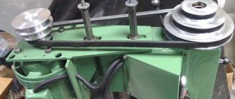
Design of the main components of the 6T13 cantilever milling machine
bed
The bed is the base unit on which the remaining components and mechanisms of the machine are mounted.
The frame is rigidly fixed to the base and fixed with pins.
Rotating head of the 6T13 cantilever milling machine
The rotating head (Fig.) is centered in the annular recess of the bed neck and is attached to it with four bolts that fit into a single groove in the bed flange.
The spindle is a two-support shaft mounted in a retractable sleeve. The axial play in the spindle is adjusted by grinding rings 3 and 4. Increased play in the front bearing is eliminated by grinding half rings 5 and tightening the nut.
The adjustment is carried out in the following order:
- the spindle sleeve extends;
- flange 6 is dismantled;
- half rings are removed;
- a screw plug is removed from the right side of the head body;
- through the hole, unscrewing screw 2 unlocks nut 1;
- Nut 1 is locked with a steel rod. By turning the spindle by the nut, the nut is tightened and this moves the inner race of the bearing. After checking the play in the bearing, the spindle is run in at maximum speed. When operating for an hour, the heating of the bearings should not exceed 60° C;
- the size of the gap between the bearing and the spindle collar is measured, after which the half rings 5 are ground to the required amount;
- the half rings are put in place and secured;
- Flange 6 is screwed in.
To eliminate radial play of 0.01 mm, the half rings must be ground by approximately 0.12 mm.
Rotation is transmitted to the spindle from the gearbox through a pair of bevel and a pair of cylindrical gears mounted in the head.
The bearings and gears of the rotary head are lubricated from the frame pump, and the spindle bearings and the sleeve moving mechanism are lubricated by extrusion.
Gearbox
The gearbox is mounted directly in the frame body. The connection of the box to the electric motor shaft is carried out by an elastic coupling, which allows misalignment in the motor installation of up to 0.5-0.7 mm.
The gearbox can be inspected through the window on the right side.
The gearbox is lubricated by a plunger pump (Fig. 9), driven by an eccentric. Pump capacity is about 2 l/min. Oil is supplied to the pump through a filter. From the pump, the oil flows to the oil distributor, from which it is discharged through a copper tube to the pump control eye and through a flexible hose to the rotary head. The gearbox elements are lubricated by splashing oil coming from the holes in the oil distributor tube located above the gearbox.
Gearbox
The gearbox allows you to select the required speed without sequentially passing through intermediate stages.
Rack 19 (Fig. 10), moved by shift handle 18, through sector 15 through fork 22 (Fig. 11) moves the main roller 29 with shift disc 21 in the axial direction.
The shift disk can be turned by the speed indicator 23 through the bevel gears 28 and 30. The disk has several rows of holes of a certain size located against the pins of the racks 31 and 33.
The racks engage in pairs with gear 32. A shift fork is attached to one of each pair of racks. When moving the disk by pressing on the pin of one of the pair, reciprocating movement of the slats is ensured.
In this case, the forks at the end of the disk stroke occupy a position corresponding to the engagement of certain pairs of gears. To eliminate the possibility of hard stop of the gears when switching, the pins of 20 racks are spring-loaded.
Fixation of the dial when choosing a speed is ensured by ball 27, which slides into the groove of sprocket 24.
The spring 25 is adjusted by the plug 26, taking into account the clear fixation of the dial and the normal force when turning it.
Handle 18 (see Fig. 10) is held in the on position by spring 17 and ball 16. In this case, the handle tenon fits into the groove of the flange.
Correspondence of speeds to the values indicated on the indicator is achieved by a certain position of the bevel wheels along the mesh. Correct engagement is established by cores at the ends of the mating tooth and cavity or by setting the pointer to the speed position of 31.5 rpm and the disk with forks to the speed position of 31.5 rpm (for machine models 6Т13Б the corresponding speed is 50 rpm) . The gap in the engagement of the conical pair should not be more than 0.2 mm, since the disk can rotate up to 1 mm due to this.
The gearbox is lubricated from the gearbox lubrication system by splashing oil.
Technical characteristics of the cantilever milling machine 6T13
| Parameter name | 6Р12 | 6Р13 | 6T12 | 6T13 |
| Basic machine parameters | ||||
| Table surface dimensions, mm | 1250 x 320 | 1600 x 400 | 1250 x 320 | 1600 x 400 |
| Maximum mass of the workpiece, kg | 250 | 300 | 400 | 630 |
| Maximum longitudinal stroke of the table (X), mm | 800 | 1000 | 800 | 1000 |
| Maximum transverse travel of the table (Y), mm | 250 | 300 | 320 | 400 |
| Maximum vertical travel of the table (Z), mm | 420 | 420 | 420 | 430 |
| Distance from the end of the spindle to the table surface, mm | 30..450 | 30..500 | 30..450 | 70..500 |
| Distance from the spindle axis to the vertical guides of the bed (overhang), mm | 350 | 420 | 380 | 460 |
| Spindle | ||||
| Main drive drive power, kW | 7,5 | 10 | 7,5 | 11 |
| Spindle speed, rpm | 40..2000 | 40..2000 | 31,5..1600 | 31,5..1600 |
| Number of spindle speeds | 18 | 18 | 18 | 18 |
| Spindle quill movement, mm | 70 | 80 | 70 | 80 |
| Movement of the spindle quill by one dial division, mm | 0,05 | 0,05 | 0,05 | 0,05 |
| Spindle head rotation angle, degrees | ±45° | ±45° | ±45° | ±45° |
| Spindle end GOST 836-62 | №3 | №3 | ||
| Spindle end GOST 24644-81, row 4, version 6 | 50 | 50 | ||
| Desktop. Submissions | ||||
| Limits of longitudinal and transverse table feeds (X, Y), mm/min | 12,5..1600 | 12,5..1600 | 12,5..1600 | 12,5..1600 |
| Limits of vertical table feeds (Z), mm/min | 4,1..530 | 4,1..530 | 4,1..530 | 4,1..530 |
| Number of table feeds (longitudinal, transverse, vertical) | 22 | 22 | 22 | 22 |
| Speed of fast movements (longitudinal, transverse/vertical) X, Y/ Z, m/min | 4/ 1,330 | 4/ 1,330 | 4/ 1,330 | 4/ 1,330 |
| Movement of the table by one dial division (longitudinal, transverse, vertical), mm | 0,05 | 0,05 | 0,05 | 0,05 |
| Table movement per one revolution of the dial (longitudinal, transverse/vertical), mm | 6/ 2 | 6/ 2 | 6/ 2 | 6/ 2 |
| Maximum permissible cutting force (longitudinal/transverse/vertical), kN | 15/ 12/ 5 | 20/ 12/ 8 | ||
| Machine mechanics | ||||
| Feed stops (longitudinal, transverse, vertical) | Eat | Eat | Eat | Eat |
| Blocking manual and mechanical feeds (longitudinal, transverse, vertical) | Eat | Eat | Eat | Eat |
| Blocking separate feed switching | Eat | Eat | Eat | Eat |
| Spindle braking | Eat | Eat | Eat | Eat |
| Overload safety clutch | Eat | Eat | Eat | Eat |
| Automatic intermittent feed | Eat | Eat | Eat | Eat |
| Electrical equipment and machine drives | ||||
| Number of electric motors on the machine | 4 | 4 | 4 | 4 |
| Main motion electric motor, kW | 7,5 | 10 | 7,5 | 11 |
| Feed drive electric motor, kW | 2,2 | 3 | 3 | 3 |
| Tool clamping motor, kW | 0,25 | 0,25 | ||
| Coolant pump electric motor, kW | 0,125 | 0,125 | 0,12 | 0,12 |
| Total power of all electric motors, kW | 10,87 | 14,37 | ||
| Dimensions and weight of the machine | ||||
| Machine dimensions (length width height), mm | 2305 1950 2020 | 2560 2260 2120 | 2280 1965 2265 | 2570 2252 2430 |
| Machine weight, kg | 3120 | 4200 | 3250 | 4300 |
- Vertical cantilever milling machines 6T12-1, 6T13-1. Operating manual 6T12-1.00.000 RE,
- Vertical console-milling machines 6T12, 6T13. Operating manual 6T12.00.000 RE,
- Vertical cantilever milling machines 6T12-29, 6T13-29. Operating manual 6T12-29.00.000 RE, 1992
- Cantilever milling machines 6T82G-1, 6T82-1, 6T12-1, 6T82SH-1, 6T83G-1, 6T83-1, 6T13-1, 6T83SH-1. Operating manual for electrical equipment 6T82G.00.000 RE1
- Avrutin S.V. Fundamentals of Milling, 1962
- Avrutin S.V. Milling, 1963
- Acherkan N.S. Metal-cutting machines, Volume 1, 1965
- Barbashov F.A. Milling 1973
- Barbashov F.A. Milling work (Vocational education), 1986
- Blumberg V.A. Milling machine handbook, 1984
- Grigoriev S.P. Practice of coordinate boring and milling work, 1980
- Kopylov Work on milling machines, 1971
- Kosovsky V.L. Handbook of a young milling operator, 1992
- Kuvshinsky V.V. Milling, 1977
- Nichkov A.G. Milling machines (Machinist's Library), 1977
- Pikus M.Yu. A mechanic's guide to repairing metal-cutting machines, 1987
- Plotitsyn V.G. Calculations of settings and adjustments of milling machines, 1969
- Plotitsyn V.G. Setting up milling machines, 1975
- Ryabov S.A. Modern milling machines and their equipment, 2006
- Skhirtladze A.G., Novikov V.Yu. Technological equipment for machine-building industries, 1980
- Tepinkichiev V.K. Metal cutting machines, 1973
- Chernov N.N. Metal cutting machines, 1988
- Frenkel S.Sh. Handbook of a young milling operator (3rd ed.) (Vocational education), 1978
Bibliography:
Related Links. Additional Information
- Milling machines: general information, classification, designation
- Comparative characteristics of cantilever milling machines of the 6N, 6M, 6R, 6T
- Feed box for console milling machines of the 6M : 6M12P, 6M13P, 6M82, 6M83, 6M82Sh, 6M83Sh
- Feed box for console milling machines of the 6P : 6P12, 6P13, 6P82, 6P83, 6P82Sh, 6P83Sh
- Feed box for console milling machines 6T : 6T12, 6T13, 6T82, 6T83, 6T82Sh, 6T83Sh
- Milling machine repair technology
- Adjustment of milling machines
- Friction clutch. Friction shaft. Friction clutches in metal-cutting machines
- Automatic cycles of milling machines (6P12)
- Testing and checking metal-cutting machines for accuracy
- Directory of universal milling machines
- Manufacturers of metal-cutting machines in Russia
- Manufacturers of milling machines in Russia
- Electrical equipment of milling machines 6T12, 6T13, 6T82, 6T82G, 6T82Sh, 6T83, 6T83G, 6T83Sh
- Electrical equipment of milling machines 6P12, 6P13, 6Р82, 6Р82Г, 6Р82Ш, 6Р83, 6Р83Г, 6Р83Ш, 6Р12Б, 6Р13Б
- Electrical equipment of milling machines 6M12P, 6M12PB, 6M13P, 6M13PB, 6M82, 6M82Sh, 6M82GB, 6M83, 6M83Sh
- Electrical equipment of milling machines 6T10, 6T80, 6T80G, 6T80Sh
- Electrical equipment of milling machines 6Р10, 6Р80, 6Р80Г, 6Р80Ш
- Electrical equipment of milling machines 6N10, 6N80, 6N80G, 6N80Sh
Electrical equipment of milling machines of the Gorky Machine Tool Plant, GZFS
Electrical equipment of milling machines of the Vilnius Zalgiris Machine Tool Plant
Designation
The alphanumeric index of the Vertical milling machine 6Р13, 6Т13, 6М13П, 6Н13П, 6Н13 means the following: number 6 is a milling machine; index P, T, M, N - designates the manufacturing plant of the machine, number 1 - designates a vertical milling machine, number 3 - standard size of the machine (table size).
| Specifications | Options |
| Dimensions of the working surface of the table, mm | 1 600 x 400 |
| Maximum longitudinal movement of the table, mm | 1 000 |
| Maximum lateral movement of the table, mm | 400 |
| Maximum vertical movement of the table, mm | 430 |
| Distance from the end of the spindle to the working surface of the table, mm | 70 — 500 |
| Spindle speed limits, min -1 | 31,5 — 1600 |
| Accelerated longitudinal movement of the table, mm/min | 4 000 |
| Accelerated lateral movement of the table, mm/min | 4 000 |
| Accelerated vertical movement of the table, mm/min | 1 330 |
| Maximum weight of the workpiece with fixture, kg | 1 250 |
| Spindle drive electric motor power, kW | 11 |
| Table drive electric motor power, kW | 3 |
| Spindle cone according to GOST 30064-93 | ISO 50 |
| Overall dimensions of the machine (L x W x H), mm | 2,570 x 2,252 x 2,430 |
| Weight of the machine with electrical equipment, kg | 4 300 |