Slope and Taper - Definition, designation on the drawing, formula for calculating slope and taper
Sometimes, in tasks on descriptive geometry or work on engineering graphics, or when performing other drawings, it is necessary to construct a slope and a cone.
In this article you will learn about what slope and taper are, how to build them, and how to correctly indicate them in the drawing. Slope. Slope is the deviation of a straight line from a vertical or horizontal position. Definition of slope. The slope is defined as the ratio of the opposite side of the angle of a right triangle to the adjacent side, that is, it is expressed by the tangent of the angle a. The slope can be calculated using the formula i=AC/AB=tga.
Construction of the slope. The example (Figure) clearly demonstrates the construction of a slope. To construct a 1:1 slope, for example, you need to lay out arbitrary but equal segments on the sides of a right angle. This slope will correspond to an angle of 45 degrees. In order to construct a slope of 1:2, you need to set aside a horizontal segment equal in value to two segments laid down vertically. As can be seen from the drawing, the slope is the ratio of the opposite side to the adjacent side, i.e. it is expressed by the tangent of the angle a.
Designation of slope on drawings. The designation of slopes in the drawing is carried out in accordance with GOST 2.307-68. The amount of slope is indicated on the drawing using a leader line. The sign and magnitude of the slope are indicated on the leader line shelf. The slope sign must correspond to the slope of the line being determined, that is, one of the straight lines of the slope sign must be horizontal, and the other must be inclined in the same direction as the slope line being determined. The slope of the sign line is approximately 30°.
What is taper? Formula for calculating taper. Designation of taper in drawings.
Taper. Taper is the ratio of the diameter of the base of the cone to the height. The taper is calculated using the formula K=D/h, where D is the diameter of the base of the cone, h is the height. If the cone is truncated, then the taper is calculated as the ratio of the difference between the diameters of the truncated cone and its height. In the case of a truncated cone, the conicity formula will look like: K = (Dd)/h.
Designation of taper in drawings. The shape and size of the cone is determined by drawing three of the listed dimensions: 1) the diameter of the large base D; 2) diameter of the small base d; 3) diameter in a given cross section Ds having a given axial position Ls; 4) cone length L; 5) cone angle a; 6) taper with . It is also allowed to indicate additional dimensions in the drawing as a reference.
The dimensions of standardized cones do not need to be indicated on the drawing. It is enough to indicate in the drawing the symbol of the taper according to the relevant standard.
Taper, like slope, can be indicated in degrees, as a fraction (simple, as a ratio of two numbers, or as a decimal), as a percentage. For example, a 1:5 taper can also be indicated as a 1:5 ratio, 11°25'16" , decimal 0.2 and percentage 20. For cones used in mechanical engineering, OCT/BKC 7652 establishes a range of normal tapers. Normal tapers - 1:3; 1:5; 1:8; 1:10; 1:15; 1:20; 1:30; 1:50; 1:100; 1:200. Also 30, 45, 60, 75, 90 and 120° can be used.
Features of constructing slope and taper
The field of drawing has developed over a fairly long period. It has been used many centuries ago to transfer accumulated knowledge and skills. Today, the manufacture of all products can be carried out exclusively using drawings. At the same time, it receives the most attention when setting up mass production. Over a long period of development of drawing, standards have been developed that can significantly increase the readability of all information. An example is GOST 8593-81. It largely characterizes the taper and slope and the methods used to display them. Descriptive geometry is used to study modern science, as well as to create various techniques. In addition, a variety of correspondence tables have been developed that can be used when carrying out direct calculations.
Various concepts such as fillet, slope and taper are displayed in a specific way. This takes into account the scope of application of the technical documentation being developed and many other points.
The features of constructing an angle and taper include the following points:
- The main lines are displayed in a bolder style, except when there is a thread on the surface.
- When carrying out work, a variety of tools can be used. It all depends on which construction method is used in a particular case. An example is a right triangle, with the help of which a right angle or a protractor is maintained.
- The display of the main dimensions is carried out depending on the features of the drawing. Most often, a basic value is indicated, with the help of which others are determined. Today, the method of direct sizing, when it is necessary to measure lines and angles using appropriate tools taking into account the scale, is practically not used. This is due to the difficulties that arise on the production line.
In general, we can say that the basic standards are taken into account by the specialist when directly carrying out the work of constructing the drawing.
Often, to represent the slope in descriptive geometry, additional lines are created, and the angle of the slope is also indicated.
In design documentation, which often displays taper, additional information, if necessary, is displayed in a separate table.
What factors influence the choice of roof slope?
Despite the fact that humanity is constantly developing and no longer depends on natural circumstances, it is still these conditions that often influence the choice of inclination.
Atmospheric precipitation, the accumulation of which threatens roof failure or the appearance of dampness and fungus.
If constant rains, downpours, thunderstorms and snowfalls are common in a given region, then the roof slope should be increased. Quickly ridding the roof of water is the key to the longevity of the structure.
In regions with strong winds, such as the steppes, it is more important than ever to find a middle ground. The wind can simply overwhelm a roof that is too high, or tear off a flat one. The most optimal roof slope is from 30 to 40 degrees
In regions with strong gusts of wind - from 15 to 25 degrees
The most optimal roof slope is from 30 to 40 degrees. In regions with strong gusts of wind - from 15 to 25 degrees.
When choosing a roof slope, it is imperative to take these two serious factors into account. Having understood this issue, further work on the flooring will be significantly simplified.
According to GOST and SNiPs, which are in force on the territory of the Russian Federation, the roof angle should be measured only in degrees. In all official data or documents, only degrees are used. However, it is easier for workers and builders “on the ground” to navigate in percentages. Below is a table of the relationship between degrees and percentages - for more convenient use and understanding.
Using the table is quite simple: we find out the initial value and correlate it with the desired indicator.
There is a very convenient tool for measuring called an inclinometer. This is a rail with a frame, in the middle there is an axis and a division scale, to which the pendulum is attached. At a horizontal level, the device shows 0. And when used vertically, perpendicular to the ridge, the inclinometer shows a degree.
In addition to this instrument, geodetic, drip and electronic instruments for measuring slope are also widely used. The degree of slope can also be calculated mathematically.
To calculate the slope angle, you need to find out two values: B - vertical height (from the ridge to the eaves), C - position (horizontal from the bottom point of the slope to the top). When dividing the first value by the second, A is the slope angle in degrees. If you need a roof angle percentage, refer to the table above.
How to Draw Slopes and Tapers
Slope characterizes the deviation of a straight line from horizontal or vertical directions. In order to construct a 1:1 slope, arbitrary but equal values are laid on the sides of a right angle (Fig. 1). Obviously, a slope of 1:1 corresponds to an angle of 45 degrees. To build a line with a slope of 1:2, two units are laid out horizontally, for a slope of 1:3 - three units, etc. As can be seen from the drawing, the slope is the ratio of the opposite side to the adjacent side, i.e. it is expressed by the tangent of the angle A. The magnitude of the slope in the drawing in accordance with GOST 2.307-68 is indicated using a leader line, on the shelf of which the slope sign and its magnitude are applied. The location of the slope sign must correspond to the line being determined: one of the straight lines of the sign must be horizontal, the other inclined at approximately an angle of 30° in the same direction as the slope line itself.
In the figure, as an example, a profile of an asymmetrical I-beam is constructed, the right flange of which has a slope of 1:16. To construct it, point A is found using the given dimensions 26 and 10.
To the side they build a line with a slope of 1:16, for which they set aside, for example, 5 mm vertically and 80 mm horizontally; draw a hypotenuse, the direction of which determines the desired slope.
Using a straight line and a square, draw a slope line parallel to the hypotenuse through point A.
Taper is the ratio of the diameter of the base of a cone to its height. In this case, taper K=d/l. For a truncated cone K = (d-d1)/l.
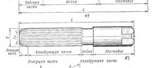
Let it be necessary to construct a conical end of a shaft according to the given dimensions: d - shaft diameter - 25 mm; I — total length of the shaft end — 60 mm; l1 — length of the conical part — 42 mm; d1 - outer thread diameter - 16 mm; K—taper 1:10 (Fig. 3, b). First of all, using the axial one, they build a cylindrical part of the shaft with a diameter of 25 mm.
This size also determines the larger base of the conical part. After this, a taper of 1:10 is built. To do this, build a cone with a base equal to 10 mm and a height equal to 100 mm (one could use a size of 25 mm, but in this case the height of the cone should be taken equal to 250 mm, which is not entirely convenient).
The generatrices of the conical part of the shaft are drawn parallel to the lines of the found taper and its length is limited to 42 mm. As you can see, the size of the smaller base of the cone is obtained as a result of the construction. This dimension is usually not included in the drawing. The notation M16X1.5 is a symbol for a metric thread, which will be discussed in more detail later.
- nn
- TBegin—>TEnd—>
- nn
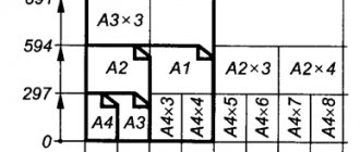
Rice. 1. Construction of slopes
n
n
Before the dimensional number characterizing the taper, a symbol is applied in the form of an isosceles triangle, the vertex of which is directed towards the vertex of the cone itself. The taper sign is placed parallel to the axis of the cone above the axis or on the shelf of a leader line ending with an arrow, as in the case of a slope inscription. The taper is selected in accordance with GOST 8593-57.
nn
nn
Rice. 2. Example of constructing slopes
- n
- n
- TBegin—>TEnd—>
- nn
Rice. 3. Constructing a taper
n
What is slope? How to determine slope? How to build a slope? Designation of slope on drawings according to GOST.
Slope . Slope is the deviation of a straight line from a vertical or horizontal position. Determination of slope. The slope is defined as the ratio of the opposite side of the angle of a right triangle to the adjacent side, that is, it is expressed by the tangent of the angle a. The slope can be calculated using the formula i=AC/AB=tga.
Construction of the slope . The example (Figure) clearly demonstrates the construction of a slope. To construct a 1:1 slope, for example, you need to lay out arbitrary but equal segments on the sides of a right angle. This slope will correspond to an angle of 45 degrees. In order to construct a slope of 1:2, you need to set aside a horizontal segment equal in value to two segments laid down vertically. As can be seen from the drawing, the slope is the ratio of the opposite side to the adjacent side, i.e. it is expressed by the tangent of the angle a.
Designation of slope on drawings . The designation of slopes in the drawing is carried out in accordance with GOST 2.307-68. The amount of slope is indicated on the drawing using a leader line. The sign and magnitude of the slope are indicated on the leader line shelf. The slope sign must correspond to the slope of the line being determined, that is, one of the straight lines of the slope sign must be horizontal, and the other must be inclined in the same direction as the slope line being determined. The slope of the sign line is approximately 30°.
What is the roof pitch angle measured in?
The designation of the roof slope on the drawings can be either in degrees or as a percentage. The roof slope is indicated by the Latin letter i.
In SNiP II-26-76, this value is indicated as a percentage (%). At the moment, there are no strict rules for indicating the size of the roof slope.
The unit of measurement for roof slope is degrees or percentages (%). Their ratios are shown in the table below.
Roof slope degree-percentage ratio
| degrees | % | degrees | % | degrees | % |
| 1° | 1,75% | 16° | 28,68% | 31° | 60,09% |
| 2° | 3,50% | 17° | 30,58% | 32° | 62,48% |
| 3° | 5,24% | 18° | 32,50% | 33° | 64,93% |
| 4° | 7,00% | 19° | 34,43% | 34° | 67,45% |
| 5° | 8,75% | 20° | 36,39% | 35° | 70,01% |
| 6° | 10,51% | 21° | 38,38% | 36° | 72,65% |
| 7° | 12,28% | 22° | 40,40% | 37° | 75,35% |
| 8° | 14,05% | 23° | 42,45% | 38° | 78,13% |
| 9° | 15,84% | 24° | 44,52% | 39° | 80,98% |
| 10° | 17,64% | 25° | 46,64% | 40° | 83,90% |
| 11° | 19,44% | 26° | 48,78% | 41° | 86,92% |
| 12° | 21,25% | 27° | 50,95% | 42° | 90,04% |
| 13° | 23,09% | 28° | 53,18% | 43° | 93,25% |
| 14° | 24,94% | 29° | 55,42% | 44° | 96,58% |
| 15° | 26,80% | 30° | 57,73% | 45° | 100% |
You can convert the slope from percent to degrees and vice versa from degrees to percent using an online converter:
Roof slope measurement
The slope angle is measured using an inclinometer or mathematically.
An inclinometer is a rod with a frame, between the slats of which there is an axis, a division scale, and to which a pendulum is attached. When the staff is in a horizontal position, the scale shows zero degrees. To measure the slope of the roof slope, the inclinometer rod is held perpendicular to the ridge, that is, at a vertical level. On the inclinometer scale, the pendulum indicates the slope of a given roof slope in degrees. This method of measuring slope has become less relevant, since various geodetic instruments for measuring slopes have now appeared, as well as drip and electronic levels with inclinometers.
Mathematical calculation of slope
You can calculate the roof slope without using geodetic and other instruments for measuring the slope. To do this you need to know two sizes:
- Vertical height (H) from the top point of the slope (usually the ridge) to the level of the bottom (eaves)
- Layout ( L ) – horizontal distance from the bottom point of the slope to the top
Using mathematical calculation, the roof slope is found as follows:
The slope angle i is equal to the ratio of the roof height H to the ground level L
i = Н : L
In order to express the value of the slope as a percentage, this ratio is multiplied by 100. Next, to find out the value of the slope in degrees, we translate using the table of ratios located above.
To make it clearer, let's look at an example:
Let it be:
Laying length 4.5 m, roof height 2.0 m.
The slope is: i = 2.0: 4.5 = 0.44 now multiply by × 100 = 44%. We convert this value from the table into degrees and get – 24°.
Minimum slope for roofing materials (coatings)
| Roof type | Minimum roof slope | ||
| in degrees | V % | in the ratio of the height of the slope to the foundation | |
| Roofs made of rolled bitumen materials: 3 and 4 layers (fused roofing) | 0-3° | up to 5% | until 1:20 |
| Roofs made of rolled bitumen materials: 2-layer (fused roofing) | from | 15 | |
| Seam roofing | from 4° | ||
| Ondulin | 5° | 1:11 | |
| Corrugated asbestos cement sheets (slate) | 9° | 16 | 1:6 |
| Ceramic tiles | 11° | 1:6 | |
| Bituminous shingles | 11° | 1:5 | |
| Metal tiles | 14° | ||
| Cement-sand tiles | 34° | 67% | |
| Wooden roof | 39° | 80% | 1:1.125 |
Converting taper to degrees
Taper is the ratio of the difference in diameters of two cross sections of a circular cone to the distance between them.
The taper has a double Slope: k=2i The taper in the drawing can be indicated in degrees, in radians and as a percentage. The taper is set to 1:5, diameter D=BC=20 mm, length l=35 mm.
It is necessary to construct the outline of the faucet plug in one of two ways: The first method. From the formula k=2i we find i=1:10. Mark points BC and construct triangle DKP so that KP:BK=1:10. Continuing BP until it intersects with the axis of the cone, we obtain the vertex of the cone S. We connect point S to point C. Setting aside a segment l=35 mm along the axis of the plug from BC and drawing a straight line through the end of this segment, perpendicular to the axis, we obtain the diameter d=EF=13 mm of the end of the plug; Second way. From the formula k=(Dd)/l we find d=EF=20-35/5=13 mm; Angle at the apex of the cone:
here the angle φ is represented in radians.
where L is the distance from the large section to the top S of the cone, and the ratio: D/(2L) = tgφ Let the taper , for example 1: 2.5, from which i=1:5 and tgφ=0.2 then its conversion to degrees is carried out according formulas:
The taper is standardized. GOST 8593-81 establishes normal tapers and cone angles
| Designation | cone | Cone- | ness | Corner | cone | Corner | slope |
| Row 1 | Row 2 | Angle units | Glad. | Angle units | Glad. | ||
| 1:500 | 1:500 | 0,0020000 | 6`52,5″ | 0,0020000 | 3`26,25″ | 0,0010000 | |
| 1:200 | 1:200 | 0,0050000 | 17`11,3″ | 0,0050000 | 8`25,65″ | 0,0025000 | |
| 1:100 | 1:100 | 0,0100000 | 34`22,6″ | 0,0100000 | 17`11,3″ | 0,0050000 | |
| 1:50 | 1:50 | 0,0200000 | 1°8`45,2″ | 0,0199996 | 34`22,6″ | 0,0099998 | |
| 1:30 | 1:30 | 0,0333333 | 1°54`34,9″ | 0,0333304 | 57`17,45″ | 0,0166652 | |
| 1:20 | 1:20 | 0,0500000 | 2°51`51,1″ | 0,0499896 | 1°25`55,55″ | 0,0249948 | |
| 1:15 | 1:15 | 0,0666667 | 3°49`5,9″ | 0,0666420 | 1°54`32,95″ | 0,0333210 | |
| 1:12 | 1:12 | 0,0833333 | 4°46`18,8″ | 0,0832852 | 2°23`9,4″ | 0,0416426 | |
| 1:10 | 1:10 | 0,1000000 | 5°43`29,3″ | 0,0999168 | 2°51`44,65″ | 0,0499584 | |
| 1:8 | 1:8 | 0,1250000 | 7°9`9,6″ | 0,1248376 | 3°34`34,8″ | 0,0624188 | |
| 1:7 | 1:7 | 0,1428571 | 8°10`16,4″ | 0,1426148 | 4°5`8,2″ | 0,0713074 | |
| 1:6 | 1:6 | 0,1666667 | 9°31`38,2″ | 0,1662824 | 4°45`49,1″ | 0,0831412 | |
| 1:5 | 1:5 | 0,2000000 | 11°25`16,3″ | 0,1993374 | 5°42`38,15″ | 0,0996687 | |
| 1:4 | 1:4 | 0,2500000 | 14°15`0,1″ | 0,2487100 | 7°7`30,05″ | 0,1243550 | |
| 1:3 | 1:3 | 0,3333333 | 18°55`28,7″ | 0,3302972 | 9°27`44,35″ | 0,1651486 | |
| 30° | 1:1,866025 | 0,5358985 | 30° | 0,5235988 | 15° | 0,2617994 | |
| 45° | 1:1,207107 | 0,8284269 | 45° | 0,7853982 | 22°30` | 0,3926991 | |
| 60° | 1:0,866025 | 1,1547010 | 60° | 1,0471976 | 30° | 0,5235988 | |
| 75° | 1:0,651613 | 1,5346532 | 75° | 1,3089970 | 37°30` | 0,6544985 | |
| 90° | 1:0,500000 | 2,0000000 | 90° | 1,5707964 | 45° | 0,7853982 | |
| 120° | 1:0,288675 | 3,4641032 | 120° | 2,0943952 | 60° | 1,0471976 |
The tapers and angles of the cones must correspond to those indicated in the drawing and table. When selecting tapers or taper angles, Row 1 should be preferred to Row 2.
Surface taper
indicated on the drawing: – by the inscription Taper indicating its value; – an arrow pointing at it with a shelf where it is written: – Taper with an indication of its value; – sign of the taper and its magnitude.
Calculator and formula for calculating the taper of a part.
Taper can be defined as the ratio of the difference between the largest cone diameter and the smallest cone diameter to the length of the cone, then the formula for determining the taper of a part will be as follows:
Also, the taper of a part can be calculated as the double tangent of the angle of inclination of the cone, the formula will be as follows:
To determine the taper, you must enter the values of the largest cone diameter, smallest cone diameter, cone length and click the “CALCULATE” button.
The result of the calculation will be the taper value of the part.
Sometimes, in tasks on descriptive geometry or work on engineering graphics, or when performing other drawings, it is necessary to construct a slope and a cone. In this article you will learn about what slope and taper are, how to build them, and how to correctly indicate them in the drawing.
Tip 3 How to calculate slope
If you need to calculate the slope of a roof slope or the slope of a road, your actions will be different, although the thesis of the calculation is identical. You should choose a formula for calculating slope a depending on the units in which you want to get the result.
Instructions
1. First of all, either realistically or mentally, build a right triangle, in which one of the sides will be a perpendicular lowered to the ground. To build such a triangle on a piece of land or a road, use a level. Determine the height at 2 points of the measured object above the sea level, as well as the distance between them.
2. If you need to detect the slope of a small object located on the ground, take a flat board or, using a level gauge, place it strictly horizontally between two points. At the lowest point, you will have to place improvised means, say, bricks, under it. Use a tape measure to measure the length of the board and the height of the bricks.
3. In order to detect the slope of the roof slope, go into the attic and from a certain point on the slope, lower the thread with the load down to the floor. Measure the length of the thread and the distance from the lowered weight to the intersection of the slope with the attic floor. Measurement methods can be very different, even up to photographing an object and measuring the sides in the photograph - your goal is to find out the length of 2 legs in the resulting right triangle.
4. If you have a fairly detailed map, a physical map of the area, calculate the slope using it. To do this, mark the extreme points and see what height symbols are marked there, find the difference between them. Measure the distances between points and use the indicated scale to calculate the actual distance
Please note that all distances must be measured in the same units, say, only in meters or only in centimeters
5. Divide the opposite leg (vertical distance) by the adjacent leg (distance between points). If you need to get the slope as a percentage, multiply the resulting number by 100%. To get the slope in ppm, multiply the result of the division by 1000‰.
6. If you need to get the slope in degrees, use the fact that the result obtained by dividing the legs is the tangent of the angle of inclination. Calculate its arctangent using an engineering calculator (mechanical or online). As a result, you will get the slope value in degrees.
Calculation and application of slope on measurement drawings
Designers, builders, architects, as well as people of a number of other professions are constantly faced with the need to calculate the slope, due to the fact that it is very difficult to find a perfectly flat area on the earth's surface. Slope is expressed in degrees or percentage. The designation in degrees shows the angle of curvature of the surface. But the slope can also be represented as the tangent of this angle, multiplied by 100%. How to calculate surface slope?
Slope is the ratio of elevation (BC) to depth (AC) and is denoted in text documents by the letter i.
For example, i=1:6
Divide the opposite leg (vertical distance) by the adjacent leg (distance between points). If you need to get the slope as a percentage, multiply the resulting number by 100%. To obtain the slope in ppm, multiply the division result by 1000‰. If you need to get the slope in degrees, take advantage of the fact that the result obtained by dividing the legs is the tangent of the angle of inclination. Calculate its arctangent using an engineering calculator, as a result you will get the slope value in degrees. On views (facades), sections, sections and diagrams, in front of the dimensional number that determines the magnitude of the slope, a sign is applied , the acute angle of which should be directed towards the slope.
The slope designation is applied directly above the contour line or on the shelf of the leader line. On the plans, the direction of the slope of the planes is indicated by an arrow, on which, if necessary, the magnitude of the slope is indicated (see figure).
Construction and designation of slope.
An example of a slope on plans. The magnitude of the slope (tangent of the angle of inclination) is indicated in the form of a simple or decimal fraction accurate to the third digit.
Slope (in construction) is an indicator of the steepness of the slope (as well as the roof slope). Slope (in geodesy) is an indicator of the steepness of the slope; the ratio of the elevation of the terrain to the horizontal elevation on which it is observed. In other words, the magnitude of the slope is equal to the tangent of the angle between the surface of the slope and the horizontal. The slope of the surface is equal to the tangent of the angle α, tanα = h/l is the ratio of the perpendicular dropped from a point on the surface to a straight surface to the length of the straight surface from the beginning of the slope (at the apex of angle α) to the perpendicular. For example, a rise of 12 m per 100 m of horizontal movement corresponds to a slope of 0.12 (12% or 120 ‰). When reading the notation, the sign “%” is pronounced “hundredths”, and “‰” - “thousands”. Source: book: Unified requirements for the execution of construction drawings.
M.: Publishing house "Architecture-S", 2004. Reference manual.
Author: Georgievsky O.V. Abstract: A reference guide on construction drawing for students of secondary and higher educational institutions. The manual is made in accordance with the requirements of GOST. This reference manual is made in accordance with the requirements of GOST ESKD (Unified System of Design Documentation) and SPDS (System of Design Documentation for Construction). The manual can be used when completing tasks in architectural and construction drawing, as well as when completing coursework and diploma projects by students of all construction specialties of secondary and higher educational institutions.
Slope
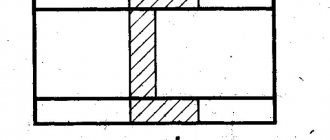
Flat surfaces of parts located obliquely are indicated in the drawing by the magnitude of the slope. We will show you how to calculate this value with an example. The wedge shown in Fig. 6.40, I, has an inclined surface, the slope of which must be determined. From the size of the largest height of the wedge, subtract the size of the smallest height: 50 – 40 = 10 mm. The difference between these values can be considered as the size of the leg of a right triangle formed after drawing a horizontal line in the drawing (Fig. 6.40, b
). The magnitude of the slope will be the ratio of the size of the smaller leg to the size of the horizontal line. In this case, you need to divide 10 by 100. The slope of the wedge will be 1:10.
Rice. 6.40.
Determining the slope amount
In the drawing, slopes are indicated by a sign and the ratio of two numbers, for example 1:50; 3:5.
If you want to depict in a drawing a surface of a certain slope, for example 3:20, draw a right triangle, one of the legs of which is three units of length, and the second is 20 of the same units (Fig. 6.41).
Rice. 6.41.
Constructing slopes and plotting their values
When drawing parts or when marking them, to construct a line along a given slope, it is necessary to draw auxiliary lines. For example, to draw a line with a slope of 1:4 through the end point of a vertical line (Fig. 6.42), a straight line segment 10 mm long should be taken as a unit of length and four such units should be set aside along the continuation of the horizontal line (i.e. 40 mm ). Then draw a straight line through the extreme division and the top point of the segment.
Rice. 6.42.
Drawing a line along a given slope
The top of the slope sign should be directed towards the slope of the surface of the part. The sign and dimension number are placed parallel to the direction in relation to which the slope is given.
Technical drawing
Slope straight line BC relative to straight line AB (Fig. 57, a) is called the relationship:i=AC/AB=tga
Taper is the ratio of the difference in diameters of two cross sections of a cone to the distance between them (Fig. 57, b)
k=(Dd)/l=2tga
Thus,
k = 2i
The slope and taper can be indicated: a) in degrees; b) a simple fraction, in the form of a ratio of two numbers or a decimal; c) as a percentage.
For example: taper expressed in degrees - 11°25'16"; ratio - 1:5; fraction -0.2; in percentage - 20%, and accordingly, the slope in degrees is 5 ° 42'38 "; ratio - 1:10; fraction—0.1; as a percentage - 10%.
For cones used in mechanical engineering, OCT/BKC 7652 establishes the following series of normal tapers - 1:3; 15; 18; 1 : 10; 1:15; 1:20; 1:30; 1:50; 1:100; 1:200, as well as 30, 45, 60, 75, 90 and 120°.
In special cases, tapers of 1:1.5 are also allowed; 1:7; 1:12 and 110°.
If it is required to draw a straight line through point A lying on straight line AB (Fig. 57, c) with a slope i=l:n relative to AB, n arbitrary units must be set aside from point A in the direction of this straight line; at the end of the resulting segment AB, restore the perpendicular EC with a length of one same unit. The hypotenuse AC of the constructed right triangle determines the desired line.
To draw a straight line of a given slope l:n through a point M that does not lie on a given straight line AB, you can proceed in two ways (Fig. 58):
1) construct a right triangle KLN (or KLN1) to the side with the ratio of legs l:n, and leg KL ll AB; then, through point M, draw the desired straight line MD (or MD1) parallel to the hypotenuse of the auxiliary triangle KN (or LN1);
2) lower the perpendicular ME from point M to line AB and take it as one. In the direction of straight line AB to the left or to the right from point E, set aside n similar segments; the hypotenuses DM or MD1 of the right triangles constructed in this way are the required straight lines.
Constructing a taper l:n relative to a given axis is reduced to constructing slopes l:n/2 on each side of the axis.
The slope or taper is most often indicated as a percentage or as a ratio of one to a whole number. Let's look at these construction methods using examples.
Example 1 . It is required to construct a cross-sectional profile of channel No. 5 OST 10017-39 (Fig. 59, a), if it is known that the slope of its flanges is 10%
We take the dimensions for construction from OST 10017-39.
We draw a vertical straight line ek equal to h = 50 mm. From points e and k we draw straight lines ec and kf, equal to the shelf width b = 37 mm. Due to the fact that both channel flanges are the same, we will limit ourselves to building only one of them. On the line ec from point c we plot a segment cm equal to (bd)/2. At point m on the perpendicular to straight line ec we lay off a segment mn equal to t = 7 mm. Through point n we draw a straight line np parallel to ec, equal to 50 mm.
Perpendicular to np from point p we draw a segment ps equal in length to ten percent of the segment np. Its value is determined from the ratio:
ps/np=10/100,
where
ps=10*50/100=5 mm.
The straight line sn is the desired straight line, which has a slope of 10% with respect to ec. Further construction of the profile does not present any difficulties.
The segment np can be taken of any length. The larger its value, the more accurately the straight slope will be constructed. However, for ease of calculation, the segment np should be taken such that its length, expressed in millimeters, ends in 0 or 5.
PRIME 2 . Construct the cross-sectional profile of I-beam No. 10 OST 10016-39 (Fig. 59, b), if it is known that the slope of its flanges is 1:6. We take the dimensions for construction from OST 10016-39.
We draw a horizontal straight line cc equal to the width of the shelf b = = 68 mm. Through point e, which is the middle of the width of the shelf, draw a vertical line. From point c we lay off a segment mс equal to
(bd)/4. At point m, perpendicular to the segment cc, draw a straight line and
on it we lay off a segment mn equal to t = 6.5 mm. Through point n we draw a horizontal line np equal to 30 mm, which will serve as a leg of a right triangle. The longer the leg, the more accurately the slope will be built. For convenience, we take the length of the segment np as a multiple of six, then the second leg will be equal to an integer. The size of the second leg is determined from the formula
i=ps/np=1/6
where i is the specified slope.
Substituting numerical values into the formula, we get
ps=30/6=5 mm.
We put off the calculated length of the second leg at point p at an angle of 90° to straight line np, we get point 5. We draw a straight line through points s and n, which will correspond to the desired straight line, which has a slope of 1:6.
The construction of mates is the same as for the channel in the previous example.
Designation of taper in the drawing
When developing technical documentation, all established standards must be provided for, since otherwise it will not be used in the future.
When analyzing the taper designation in the drawings, you need to pay attention to the following points:
- The diameter of the large base is displayed. The figure under consideration is formed by a body of rotation, which is characterized by a diametrical criterion. In the case of a cone, there may be several of them, and the change in the criterion occurs slowly, not stepwise. Basically, a similar figure has a larger diameter, and also a transitional one in the case of a step.
- Apply the diameter of the smaller base. The smaller base is responsible for forming the required angle.
- The length of the cone is calculated. The distance between the smaller and larger Base is considered a criterion for length.
- Based on the constructed image, the angle is set. Basically, the necessary calculations are carried out for this. In the case of determining the size from a printed image using a specialized measuring device, the accuracy is significantly reduced. The second method is used in the case of creating a drawing for the manufacture of non-critical parts.
The simplest notation of taper also takes into account displays of additional dimensions, for example, reference. In most cases, the taper symbol is used, which makes it possible to immediately understand the difference in diameters.
There are quite a lot of different parameters that affect the definition of taper. The properties include the following:
- The angle can be specified in degrees as a fraction or as a percentage. The choice depends on the area of use of the drawing. An example is that in the mechanical engineering field the value of a degree is indicated.
- In the mechanical engineering field, the concept of normal taper is included in a special group. It varies in a specific range and can be 30, 45, 60, 75, 90, 120°. Similar criteria are typical for most products that are used during the assembly of a wide variety of mechanisms. At the same time, maintaining similar values is much easier when using turning equipment. However, if necessary, inaccurate angles can be maintained, everything will depend on the specific case.
- When drawing key dimensions, a drawing font is used. It is distinguished by an unlimited number of properties that must be provided. For correct display, tabular information is used.
- To begin with, the taper icon is indicated from which the arrow is drawn and the value is displayed. The display characteristics in most cases depend on the drawing. In most cases, there are a lot of different sizes applied, which makes taper application much more difficult. This is why it is possible to use several different methods for displaying similar information.
In the drawing, the criterion in question is marked in the form of a triangle. This requires a digital value that can be calculated using a variety of formulas.
What is taper? Formula for calculating taper. Designation of taper in drawings
Taper
. Taper is the ratio of the diameter of the base of the cone to the height. The taper is calculated using the formula K=D/h, where D is the diameter of the base of the cone, h is the height. If the cone is truncated, then the taper is calculated as the ratio of the difference between the diameters of the truncated cone and its height. In the case of a truncated cone, the conicity formula will look like: K = (Dd)/h.
Designation of taper in drawings
. The shape and size of the cone is determined by drawing three of the listed dimensions: 1) the diameter of the large base D; 2) diameter of the small base d; 3) diameter in a given cross section Ds having a given axial position Ls; 4) cone length L; 5) cone angle a; 6) taper with . It is also allowed to indicate additional dimensions in the drawing as a reference.
The dimensions of standardized cones do not need to be indicated on the drawing. It is enough to indicate in the drawing the symbol of the taper according to the relevant standard.
Taper, like slope, can be indicated in degrees, as a fraction (simple, as a ratio of two numbers or as a decimal), or as a percentage. For example, a 1:5 taper can also be expressed as a 1:5 ratio, 11°25'16", with a decimal of 0.2 and a percentage of 20. For tapers used in mechanical engineering, OCT/BKC 7652 specifies a range of normal tapers. Normal tapers - 1:3; 1:5; 1:8; 1:10; 1:15; 1:20; 1:30; 1:50; 1:100; 1:200. Also 30, 45, 60, 75, 90 and 120° can be used.
№18
| Drawing font |
| A font (from German Schrift) is a drawing, an outline of letters of someone’s alphabet, numbers and symbols. Drawing fonts (GOST 2.304-81) are intended for making inscriptions, drawing symbols and dimensional numbers on drawings. To carry out inscriptions in drawing, GOST is used. GOST establishes the numbers of drawing fonts (1.8; 2.5; 3.5; 5; 7; 10; 14; 20; 28; 40) of Russian, Latin and other alphabets. The first “Fonts for Inscriptions” standard was developed and approved in 1919. The font number corresponds to the height (h) of the capital letter. For example, font number 5 has a capital letter height of 5 mm. The height of the letter is measured perpendicular to the base of the line. The font is made with an inclination of 75° (GOST allows for inscriptions in a drawing font without an inclination). For the convenience of writing letters in a drawing font, an auxiliary grid is built (Fig. 35), which is performed as follows. Draw the bottom and top lines of the line, the distance between which is equal to the height of the capital letter. Mark the width of the letters and the distance between them on the bottom line of the line (Table 3). Using the angles of 45° and 30° of the squares, the inclination of the letters in the line is equal to 75°. Consider the outline of the letters of the drawing font (Fig. 35-37). They differ in the presence of horizontal, vertical, inclined lines and curves, width and height. The figures show (arrows) the sequence of each letter.
|
№19
Detachable connections
Currently, detachable connections have become widespread in mechanical engineering: threaded, gear (spline), keyed, pin, cotter pin, wedge, and articulation connections.
Detachable connections of machine parts made using threads have become widespread in modern mechanical engineering. A threaded connection can ensure relative immobility of parts or movement of one part relative to another. The main connecting element in a threaded connection is the thread.
carved
is a surface formed by the helical movement of a flat contour along a cylindrical or conical surface. In this case, a helical protrusion of the corresponding profile is formed, limited by helical and cylindrical or conical surfaces (Fig. 2.2.1, a).
Fig 2.2.1
Fig 2.2.2
Threads are classified according to the shape of the surface on which it is cut (cylindrical, conical), according to the location of the thread on the surface of the rod or hole (external, internal), according to the shape of the profile (triangular, rectangular, trapezoidal, round), purpose (fastening, fastening and sealing , running, special, etc.), the direction of the helical surface (left and right) and the number of passes (single-start and multi-start).
All threads are divided into two groups: standard and non-standard; For standard threads, all their parameters are determined by standards.
The main thread parameters are determined by GOST 11708-82. The thread is characterized by three diameters: external d (D), internal d1 (D1) and middle d2 (D2).
The diameters of the external thread are designated d, d\, d2, and the diameters of the internal thread in the hole are D, D1 and D2.
The outer diameter of the thread d (D) is the diameter of an imaginary cylinder described around the tops of the external thread or the valleys of the internal thread. This diameter is decisive for most threads and is included in the thread designation.
Fig 2.2.3
Profile
thread - the contour of the thread section with a plane passing through its axis (Fig. 2.2.1, 2.2.2).
Profile angle
thread - the angle between the sides of the profile (Fig. 2.2.2).
Step
thread P - the distance between adjacent sides of the same name of the profile in the direction parallel to the thread axis (Fig. 2.2.1).
Thread stroke t is the distance between the nearest identical sides of a profile belonging to the same screw surface in a direction parallel to the thread axis (Fig. 2.2.1). In a single-start thread (Fig. 2.2.1, a) the stroke is equal to the pitch, and in a multi-start thread (Fig. 2.2.1, b) - the product of the pitch P and the number of starts n(t = lP).
In Fig. 2.2.3, a - thread length l, thread length with full profile l1.
Escape
thread - a section of an incomplete profile in the zone of transition of the thread into the main part of the object lз.
Falsehood
thread l4 - the size of the unthreaded part of the surface between the ends of the rung and the supporting surface of the part.
Undercut
thread /2 includes thread run-out and under-run.
To eliminate runaway or undercut threads, groove
b is performed (Fig. 2.2.3, b).
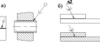
To make it easier to screw in a threaded rod, a conical chamfer is made at the end of the thread at an angle of 45° (Fig. 2.2.3, b).
Let's look at standard general purpose threads.
Metric thread
is the main fastening thread. This is a single-start thread, mostly right-handed, with large or small pitch. The metric thread profile is an equilateral triangle. The protrusions and protrusions of the thread are blunted (Fig. 2.2.4) (GOST 9150-81).
Cylindrical pipe thread
has a profile in the form of an isosceles triangle with an apex angle of 55° (Fig. 2.2.5), the peaks and valleys are rounded. This thread is used in pipelines and pipe connections (GOST 6351-81).
Fig 2.2.4
Fig 2.2.5
Fig 2.2.6
Fig 2.2.7
Trapezoidal thread
serves to transmit movement and effort. The profile of a trapezoidal thread is an isosceles trapezoid with an angle between the sides of 30° (Fig. 2.2.6). For each diameter, the thread can be single-start or multi-start, right-handed or left-handed (GOST 9484-81).
Thread persistent
has a profile of an unequal trapezoid (Fig. 2.2.7). The profile depressions are rounded and there are three different pitches for each diameter. Serves to transmit movement with large axial loads (GOST. 10177-82).
Round thread
for bases and sockets, for safety glasses and lamps, for sanitary fittings (GOST 13536-68) has a profile obtained by pairing two arcs of the same radius (Fig. 2.2.8) (GOST 13536-68).
Conical inch thread
60° (GOST 6111-52) is used for hermetic connections in pipelines of machines and machines; cut on a conical surface with a taper of 1: 16 (Fig. 2.2.9).
Fig 2.2.8
Fig 2.2.9
Conical pipe thread
has a profile similar to the profile of a cylindrical pipe thread; used in valves and gas cylinders. It is possible to connect pipes that have a conical thread (taper 1:16) with products that have a cylindrical pipe thread (GOST 6211-81).
Special
threads are threads with a standard profile, but different from the standard diameter or thread pitch, and threads with a non-standard profile.
Non-standard
threads -
square and rectangular
(Fig. 2.2.10) - are manufactured according to individual drawings, on which all thread parameters are specified.
Thread image
in the drawing is carried out in accordance with GOST 2.311-68. On the rod, the threads are depicted with solid main lines along the outer diameter and solid thin lines along the inner diameter. In Fig. 2.2.11, a shows the thread on the cylinder, and in Fig. 2.2.11, b - on a cone.
Fig 2.2.10
Fig 2.2.11
Fig 2.2.12
In the hole, the threads are depicted with solid main lines along the internal diameter and solid thin lines along the outer diameter. In Fig. 2.2.12, and the thread is shown in a cylindrical hole, and in Fig. 2.2.12, b - conical.
In images obtained by projecting a threaded surface onto a plane perpendicular to its axis, a continuous thin line is drawn with an arc 3/4 of the circumference, open anywhere, but not ending at the axes. When depicting a thread, a solid thin line is drawn at a distance of at least 0.8 mm from the main line and no more than the thread pitch. The visible thread boundary is drawn as a solid base line at the end of the full thread profile to the line of the outer diameter of the thread. The thread run-out is depicted as a solid thin line, as shown in Fig. 2.2.13.
Chamfers on a threaded rod or in a threaded hole that do not have a special structural purpose are not depicted in projection onto a plane perpendicular to the axis of the rod or hole. A solid thin line of the thread image should intersect the chamfer boundary line (Fig. 2.2.13, 2.2.14). Hatching in sections and sections is brought to a solid main line.
Fig 2.2.13
Fig 2.2.14
Fig 2.2.15
A thread with a non-standard profile is depicted as shown in Fig. 2.2.15, with all dimensions and additional data with the addition of the word “thread”.
In threaded connections, the thread is conventionally drawn on the rod, and in the hole - only that part of the thread that is not covered by the rod (Fig. 2.2.16).
The thread designation includes: thread type, size, thread pitch and stroke, tolerance range, accuracy class, thread direction, standard number.
The type of thread is conventionally designated: M - metric thread (GOST 9150-81); G - cylindrical pipe thread (GOST 6357-81); Tg - trapezoidal thread (GOST 9484-81); S—thrust thread (GOST 10177-82); Rd - round thread (GOST 13536-68); R — pipe conical outer (GOST 6211-81); Rr - internal conical (GOST 6211-81); Rp - internal cylindrical (GOST 6211-81); K - conical inch thread (GOST 6111-52).
Size
conical threads and cylindrical pipe threads are conventionally designated in inches (1″ = 25.4 mm); for all other threads, the outer diameter of the thread is indicated in millimeters.
Step
threads are not indicated for metric threads with coarse pitch and for inch threads; in other cases it is indicated. For multi-start threads, the thread designation includes the thread lead, and the pitch is indicated in parentheses.
Fig 2.2.16
Fig 2.2.17
Direction
threads are indicated for left-hand threads (LH) only.
The tolerance field and thread accuracy class may not be indicated on training drawings.
Examples of thread designations: M 30 - metric thread with an outer diameter of 30 mm and a large thread pitch; M 30 x 1.5 - metric thread with an outer diameter of 30 mm, fine pitch 1.5 mm; G 1 1/2-A— cylindrical pipe thread with a size of 1 1/2″, accuracy class A; Tg 40×6 - single-start trapezoidal thread with an outer diameter of 40 mm and a pitch of 6 mm; Tg 20 x 8 (P4) - double-start trapezoidal thread with an outer diameter of 20 mm, a stroke of 8 mm and a pitch of 4 mm; S 80 x 10 - single-start thrust thread with an outer diameter of 80 mm and a pitch of 10 mm; S 80 x 20 (P10) - double-start thrust thread with an outer diameter of 80 mm, a stroke of 20 mm and a pitch of 10 mm; Rdl6 - circular thread with an outer diameter of 16 mm; Rdil6LH—round thread with a diameter of 16 mm, left; R 1 1/2—conical pipe thread with a size of 1 1/2″. K 1 1/2 GOST 6111-52 - inch conical thread with a size of 1 1/2″. Thread designations according to GOST 2.311-68 refer to the outer diameter, as shown in Fig. 2.2.17.
Fig 2.2.18
The designation of conical threads and cylindrical pipe threads is applied as shown in Fig. 2.2.18, a, b, c.
The parts are connected using threaded products.
Standard threaded products include threaded fasteners (bolts, screws, nuts, studs). The technical requirements establish 12 accuracy classes for screws, bolts and studs and 7 accuracy classes for nuts. The types and symbols of coatings for fasteners have also been established.
The structure of symbols for fasteners includes: 1 - name of the product (bolt, screw, etc.); 2 - execution (version I is not indicated); 3 - designation of metric thread and its diameter; 4 — thread pitch (for small metric); 5 - designation of the thread tolerance field; 6 - length of bolt, screw, stud in mm; 7 — accuracy class; 8 - grade of steel or alloy; 9 — designation of the type of coating; 10 — coating thickness in mm; 11 - number of the standard for the design of the fastener and its dimensions.
In educational drawings, positions 5, 7, 8, 9, 10 in an engineering graphics course may not include the product designation in the condition, since it is impossible to assign these parameters justifiably without special knowledge.
Bolt
It is a cylindrical rod with a head at one end and a thread at the other end. Bolts are used (together with nuts and washers) to fasten two or more parts. There are various types of bolts, differing from each other in the shape and size of the head and shaft, thread pitch, manufacturing accuracy and performance.
Fig 2.2.19
Fig 2.2.20
Bolts with hexagonal heads have from three (Fig. 2.2.19) to five designs: version 1 - without holes (in the head and rod); version 2 - with a hole on the threaded part of the rod; version 3 - with two holes in the bolt head.
When depicting a bolt in a drawing, two types are performed (Fig. 2.2.20) according to the general rules and the dimensions of bolt length l, thread length /o, wrench size S and thread designation Md are indicated. The height H of the head in the length of the bolt is not included. Hyperbolas formed by the intersection of the conical chamfer of the bolt head with its faces are replaced by other circles.
Examples of bolt symbols: Bolt
Ml2 x 60 GOST 7798-70 - with a hex head, first design, with M12 thread, coarse thread pitch, bolt length 60 mm.
Bolt
2M12 x 1.25 x 60 GOST 7798-70 - with fine metric thread M12x1.25, second version, bolt length 60 mm.
Screw
It is a cylindrical rod with a thread at one end and a head at the other end. According to their purpose, screws are divided into fastening and installation screws. Screw fasteners are used to connect parts by screwing the threaded part of the screw into one of the parts being connected.
Set screws are used to secure the parts together. Their rod is completely cut, they have a cylindrical or conical pressure end or a flat end (Fig. 2.2.21).
Mounting screws come in four designs; version 1 - the thread diameter is larger than the diameter of the smooth part of the rod (Fig. 2.2.22); version 2 - the thread diameter is equal to the diameter of the smooth part; version 3 and the screw head has a Phillips slot for a screwdriver.
Fig 2.2.21
Fig 2.2.22
Depending on the operating conditions, screws are manufactured (Fig. 2.2.23) with a cylindrical head (GOST 1491-80), a semicircular head (GOST 17473-80), a semi-countersunk head (GOST 17474-80) or a countersunk head (GOST 17475-80) with a slot, as well as with a turnkey head and with corrugation.
The height of the head is not included in the length of the screw, with the exception of screws with a countersunk head (Fig. 2.2.23).
In the drawing, the shape of a slotted screw is completely conveyed by one image on a plane, parallel to the axis of the screw. In this case, indicate the thread size, screw length, length of the threaded part (lо = 2d + 6 mm) and the symbol of the screw according to the relevant standard.
Examples of screw symbols: Screw M12x50 GOST 1491-80 - with a cylindrical head, first design, with M12 thread with a coarse pitch, 50 mm long;
Fig 2.2.23
Fig 2.2.24
Screw 2M12x1, 25×50 GOST 17475-80 - with countersunk head, second version, with fine metric thread with a diameter of 12 mm and a pitch of 1.25 mm, screw length 50 mm.
Hairpin
It is a cylindrical rod with threads at both ends (Fig. 2.2.24). A pin is used to connect two or more parts. One end of the stud 1\ is screwed into the threaded hole of the part, and a nut is screwed onto the other end \o. Studs are produced with two threaded ends of equal length for parts with smooth through holes. The length of the smooth part of the stud rod must be at least 0.5d.
The design and dimensions of the studs are determined by standards depending on the length of the threaded end: GOST 22032-76l1= 1.0d - the stud is screwed into steel, bronze, brass; GOST 22034-76 l1, = 1.25d; GOST 22036—76l1 = 1.6d—the stud is screwed into cast iron; GOST 22038—76 l1 = 2d; GOST 22040-76 l1 = 2.5d - the stud is screwed into light alloys.
When depicting a stud, only one view is drawn on a plane parallel to the axis of the stud, and the dimensions of the thread, the length of the stud and its symbol are indicated. Examples of stud symbols:
Stud M8 x 60 GOST 22038-76 - with a large metric thread with a diameter of 8 mm, stud length 60 mm, intended for screwing into light alloys, length of the screwed end 16 mm;
Stud M8 x 1.0 x 60 GOST 22038-76 - the same, but with a fine thread pitch of -1.0 mm.
screw
- a fastener with a threaded hole in the center. It is used for screwing onto a bolt or stud until it stops in one of the parts to be connected. Depending on the name and operating conditions, the nuts are hexagonal, round, wing, shaped, etc. Hexagonal nuts are most widely used. They are manufactured in three versions: version l - with two conical chamfers (Fig. 2.2.25); version 2 - with one conical chamfer; version 3 - without chamfers, but with a conical protrusion at one end.
The shape of the nut in the drawing is fully conveyed by its two views: on the projection plane parallel to the nut axis, half of the view is combined with half of the frontal section, and on the plane perpendicular to the nut axis, from the chamfer side.
Fig 2.2.25
The drawing indicates the thread size, wrench size S and gives the designation of the nut according to the standard.
Examples of symbols for nuts: Nut M12 GOST 5915-70 - first version, with a thread diameter of 12 mm, large thread pitch; Nut 2M12 x 1.25 GOST 5915-70 - second version, with fine metric thread with a diameter of 12 mm and a pitch of 1.25 mm.
A washer is a turned or stamped ring that is placed under a nut, screw or bolt head in threaded connections. The flatness of the washer increases the supporting surface and protects the part from scuffing when screwing the nut with a wrench. In order to protect the threaded connection from spontaneous loosening under conditions of vibration and alternating loads, spring washers in accordance with GOST 6402-70 and lock washers with tabs are used.
Round washers according to GOST 11371-78 have two versions (Fig. 2.2.26): version 1 - without chamfer, version 2 - with chamfer. The shape of a round washer is fully conveyed by one image on a plane parallel to the axis of the washer.
The internal diameter of the washer is usually 0.5...2.0 mm larger than the diameter of the bolt shaft on which the washer is placed. The symbol of the washer also includes the thread diameter of the rod, although the washer itself does not have a thread.
Examples of washer symbols:
Fig 2.2.26
Fig 2.2.27
Washer 20 GOST 11371-78 - round, first version, for a bolt with M20 thread; Washer 2.20 GOST 11371-78 - the same washer, but of a second design.
Pipeline connecting parts (couplings, elbows, tees, etc.) are threaded connections made of ductile iron and intended for connecting pipes in pipelines (Fig. 2.2.27). Pipes are used in communications transporting liquid or gas, as well as for laying cables.
The design and dimensions of pipeline connecting parts are determined by standards. The ends of the pipes have external threads, and the connecting parts have internal threads. The main parameter of the parts of pipe connections is the nominal diameter Dy - the internal diameter of the pipes in millimeters. The connecting parts of the pipelines are coated mainly with zinc.
Examples of symbols for connecting parts of pipelines: Long coupling 20 GOST 8955-75 - straight, non-galvanized, for pipes with a nominal bore of 20 mm; Angle Ts-25 GOST 8946-75 - straight, galvanized, for pipes with a nominal bore of 25 mm.
Images of threaded connections in the drawings are made in accordance with the requirements of the standards. Threaded connections are fixed threaded connections. These include connecting parts using bolts, screws, studs, nuts and pipeline fittings.
The image of a threaded connection consists of the parts depicted and connected. There are constructive, simplified and conventional images of fasteners and their connections.
Fig 2.2.28
Fig 2.2.29
When depicting a constructive image, the dimensions of the parts and their elements exactly correspond to the standards. In a simplified representation, the dimensions of fasteners are determined by conventional relationships depending on the diameter of the thread and chamfers, splines, threads in blind holes, etc. are drawn in a simplified manner.
Symbols are used for fastener rod diameters of 2 mm or less. Simplified and conventional images of fasteners are established by GOST 2.315-68. This section provides simplified images of fasteners in threaded connections that are recommended in training drawings.
A bolted connection consists of a bolt, nut, washer and connected parts. Through holes with a diameter of d0 = (1.05...1.10)d
, where d is the diameter of the bolt thread. Insert a bolt into the hole, put a washer on it and screw the nut until it stops (Fig. 2.2.28).
The length of the bolt is determined by the formula l = Н1+ Н2 + SШ + Н + К
, where H1 and H2 are the thickness of the parts being connected; Sm—thickness of the washer, SSh = 0.15d; H—nut height, H = 0.8d; K is the length of the protruding bolt shaft, K = 0.35d.
The gauge bolt length is rounded to the nearest standard bolt length.
In the drawing of a bolted connection (Fig. 2.2.28), at least two images are made - on a projection plane parallel to the axis of the bolt, and on a projection plane perpendicular to its axis (from the nut side). When depicting a bolted connection in section, the bolt, nut and washer are shown uncut. The head of the bolt and the nut in the main view are depicted with three faces. Adjacent parts are hatched with an inclination in different directions. The drawing of a bolted connection indicates three dimensions: thread diameter, bolt length and bolt hole diameter.
The symbols of the bolt, nut and washer are written in the specifications of the assembly drawing.
Hairpin
the connection consists of a stud, washer, nut and connected parts. Connecting parts with a pin is used when there is no room for a bolt head or when one of the parts being connected has a significant thickness. In this case, it is not economically feasible to drill a deep hole and install a long bolt. The pin connection reduces the weight of the structures. One of the parts connected by a pin has a recess with a thread - a socket for a pin, which is screwed into it with end l1 (see Fig. 2.2.24). The remaining parts to be connected have through holes with a diameter d0 = (1.05...1.10)d, where d is the diameter of the stud thread. The socket is first drilled to a depth l2, which is 0.5d greater than the screwed end of the stud, and then a thread is cut into the socket. At the entrance to the socket, a chamfer is made with = 0.15d (Fig. 2.2.29, a). With a pin screwed into the socket, the parts are then connected as in the case of a bolted connection.
The length of the pin is determined by the formula l = H2 + SШ + H+ K, where H2 is the thickness of the attached part; SSh—thickness of the washer; H—nut height; K is the length of the protruding end above the nut. The estimated length of the stud is rounded to the standard value. In the drawing of a stud joint, the separation line of the parts to be connected must coincide with the thread boundary of the screwed-in threaded end of the stud (Fig. 2.2.29, b). The pin socket ends in a conical surface with an angle of 120°. It is almost impossible to cut a thread to the end of the socket, but on assembly drawings it is allowed to depict a thread for the entire depth of the socket.
The drawing of a stud connection shows the same dimensions as the drawing of a bolted connection. The hatching in the threaded connection of the stud with the part into which the stud is screwed, in the section, is brought to a continuous main thread line on the stud and in the socket.
Fig 2.2.30
Screw connection
includes parts to be connected and screw and washer. In connections with countersunk screws and set screws, do not use a washer.
One of the parts to be connected should have a threaded socket for the end of the screw, and the other should have a smooth through hole with a diameter dо= =(1.05...1.10)d. If a screw with a countersunk or semi-countersunk head is used, then the corresponding side of the hole in the part must be countersunk for the screw head (Fig. 2.2.30).
The length of the screw is determined by the formula l = Н = SH + l1, where Н is the thickness of the attached part; SSh—thickness of the washer; l1 is the length of the screwed-in threaded end of the screw, which is assigned for the corresponding material, as for a stud.
The estimated screw length is rounded to the standard length value.
The depiction of a screw connection in the drawing is similar to a bolted connection in relative dimensions. The relative sizes of the screw heads are shown in Fig. 2.2.31.
On a screw connection, the thread boundary on the screw shaft must be inside a smooth hole; the thread margin not used when screwing in is approximately three thread pitches (Z.P). If the diameter of the screw head is less than 12 mm, then it is recommended to depict the slot as one thick line. In the top view, the slot in the head is shown rotated 45°. Three dimensions are indicated on the connection drawing: thread diameter, screw length, and hole diameter for the passage of the screw.
Pipe connection
consists of connected pipes and pipeline connecting parts. When connecting two pipes with a coupling, in addition to the coupling, the connection includes a lock nut and a gasket (Fig. 2.2.32).
Fig 2.2.31
Drawings of pipe connections are made according to the dimensions of their parts as structural drawings, without simplifications. Before starting to draw a pipe connection, it is necessary to select the dimensions of the pipes and connecting parts based on the value of the nominal bore Dy from the tables of the relevant standards.
The rules for making drawings of pipes and pipelines are set out in more detail in GOST 2.411-72.
Screw
(running)
connections
refer to movable detachable connections. In these connections, one part moves relative to another part along a thread. Typically, these connections use trapezoidal, thrust, rectangular and square threads. Drawings of screw connections are made according to general rules.
Serrated
(spline)
connection
is a multi-key connection in which the key is integral with the shaft and located parallel to its axis. Toothed joints, like keyed joints, are used to transmit torque, as well as in structures that require parts to move along the axis of the shaft, for example, in gearboxes.
Fig 2.2.32
Fig 2.2.33
Fig 2.2.34
Due to the large number of projections on the shaft, a gear connection can transmit more power than a key connection and provide better alignment of the shaft and wheel.
According to the cross-sectional shape, the teeth (splines) are straight-sided, involute and triangular (Fig. 2.2.33). GOST 2.409-74 establishes conventional images of gear shafts, holes and their connections.
The circles and forming surfaces of the protrusions (teeth) of the shafts and holes are shown along the entire length by main lines (Fig. 2.2.34). The circles and generatrices of the surfaces of the depressions are shown by solid thin lines, and on longitudinal sections - by solid main lines.
When depicting gear joints and their parts that have an involute or triangular profile, the pitch circles and generatrices of the pitch surfaces are shown with a dash-dotted thin line (Fig. 2.2.34, b).
Fig 2.2.35
On a plane perpendicular to the axis of the gear shaft or hole, the profile of one tooth (protrusion) and two cavities is shown, and the chamfers at the end of the spline shaft and in the hole are not shown.
The boundary of the toothed surface of the shaft, as well as the boundary between the teeth of the full profile and the run-out, is shown by a solid thin line (Fig. 2.2.34, a).
In longitudinal sections, the teeth are conventionally aligned with the plane of the drawing and are shown uncut, and in joints in the hole, only that part of the protrusions is shown that is not covered by the shaft (Fig. 2.2.34, b).
The symbol of the spline shaft or hole according to the relevant standard is placed in the table of parameters for the manufacture and control of connection elements. The symbol of the connection may be indicated in the drawing with a mandatory reference to the standard on a leader shelf drawn from the outer diameter of the shaft (Fig. 2.2.35).
Keyed connection
consists of a shaft, wheel and key. A key (Fig. 2.2.36) is a part of a prismatic (prismatic or wedge keys) or segmental (segment keys) shape, the dimensions of which are determined by the standard. Keys are used to transmit torque.
A key is placed in a special groove on the shaft. The wheel is placed on the shaft so that the groove of the wheel hub hits the protruding part of the key. The dimensions of the grooves on the shaft and in the wheel hub must correspond to the cross-section of the key.
Fig 2.2.36
Fig 2.2.37
The dimensions of the parallel keys are determined by GOST 23360-78; dimensions of connections with wedge keys - GOST 24068-80; dimensions of connections with segment keys - GOST 24071-80.
Prismatic keys come in regular and guide types. The guide keys are attached to the shaft with screws; they are used when the wheel moves along a shaft.
According to the shape of the ends of the key, there are three designs: version 1 - both ends are rounded; version 2 - one end is rounded, the second is flat; version 3 - both ends are flat.
The working surfaces of prismatic and segment keys are the lateral edges, while for wedge keys the upper and lower edges are wide, one of which has a slope of 1:100.
The cross sections of all keys have the shape of rectangles with small chamfers or rounded. The cross-sectional dimensions of the keys are selected depending on the diameter of the shaft, and the length of the keys is selected depending on the transmitted forces.
The symbols of keys are determined by standards and include: name, design, dimensions, standard number. An example of a key designation: Key 10 x 8 x 60 GOST 23360-78 - prismatic, first design, with cross-sectional dimensions 10x8 mm, length 60 mm.
Drawings of keyed connections are made according to general rules. The keyed connection is shown in a frontal section by the axial plane (Fig. 2.2.37). In this case, the key is shown uncut; a local cut is made on the shaft. The second image of a keyed connection is a section through a plane perpendicular to the shaft axis. The gap between the bases of the groove in the bushing (wheel hub) and the key is shown enlarged.
Pin connection
(Fig. 2.2.38) - cylindrical or conical - used for precise mutual fixation of fastened parts. Cylindrical pins ensure repeated assembly and disassembly of parts.
Tables for selecting the diameter of a drill for threading
When making an internal thread, a hole is pre-drilled for it. It is not equal to the diameter of the thread, since when cutting, part of the material is not removed in the form of chips, but is squeezed out, increasing the size of the protrusions. Therefore, before application, it is necessary to select the diameter of the drill bit for the thread. This can be done using tables. They are available for every type of thread, but here are the most popular ones - metric, inch, pipe.
| Metric thread | Inch thread | Pipe thread | |||||
| Thread diameter, inches | Thread pitch, mm | Drill diameter, mm | Thread diameter, inches | Thread pitch, mm | Drill diameter, mm | Thread diameter, inches | Threaded hole diameter, mm |
| M1 | 0.25 | 0,75 | 3/16 | 1.058 | 3.6 | 1/8 | 8,8 |
| M1.4 | 0,3 | 1,1 | 1/4 | 1.270 | 5.0 | 1/4 | 11,7 |
| M1.7 | 0,35 | 1,3 | 5/16 | 1.411 | 6.4 | 3/8 | 15,2 |
| M2 | 0,4 | 1,6 | 3/8 | 1.588 | 7.8 | 1/2 | 18,6 |
| M2.6 | 0,4 | 2,2 | 7/16 | 1.814 | 9.2 | 3/4 | 24,3 |
| M3 | 0,5 | 2,5 | 1/2 | 2,117 | 10,4 | 1 | 30,5 |
| M3.5 | 0,6 | 2,8 | 9/16 | 2,117 | 11,8 | — | — |
| M4 | 0,7 | 3,3 | 5/8 | 2,309 | 13,3 | 11/4 | 39,2 |
| M5 | 0,8 | 4,2 | 3/4 | 2,540 | 16,3 | 13/8 | 41,6 |
| M6 | 1,0 | 5,0 | 7/8 | 2,822 | 19,1 | 11/2 | 45,1 |
| M8 | 1,25 | 6,75 | 1 | 3,175 | 21,3 | — | — |
| M10 | 1,5 | 8,5 | 11/8 | 3,629 | 24,6 | — | — |
| M12 | 1,75 | 10,25 | 11/4 | 3,629 | 27,6 | — | — |
| M14 | 2,0 | 11,5 | 13/8 | 4,233 | 30,1 | — | — |
| M16 | 2,0 | 13,5 | — | — | — | — | — |
| M18 | 2,5 | 15,25 | 11/2 | 4,33 | 33,2 | — | — |
| M20 | 2,5 | 17,25 | 15/8 | 6,080 | 35,2 | — | — |
| M22 | 2,6 | 19 | 13/4 | 5,080 | 34,0 | — | — |
| M24 | 3,0 | 20,5 | 17/8 | 5,644 | 41,1 | — | — |
Once again, please note that the diameter of the drill bit for the thread is given for large (standard thread)
Slope calculator
Slope calculator
will help you calculate the slope, elevation or distance at the right time without any problems.
The calculator can calculate the roof slope
.
pipeline slope
.
slope of the stairs
.
road slope
, etc.
It is also possible to calculate the elevation between points or the distance from point to point (useful in geodesy).
Operating procedure:
1. Select the value that you need to calculate2. Select in which unit of measurement you want to set/calculate the slope (3 types to choose from: degrees, ppm, percent)3. Set the 1st unknown4. Set the 2nd unknown5. Click the “Calculation” button
For reference:
- slope in degrees is calculated using the tangent of the angle:
tgx = h / L
- slope in ppm is calculated using the following formula:
x = 1000 * h / L
- slope in percentage is calculated using the following formula:
x = 100 * h / L
Slope calculator
created as an addition to the main online calculations on the site, and if you liked it, then do not forget to tell your friends and colleagues about it.
Formula for determining taper
You can independently calculate the taper by using various formulas. It is worth considering that in most cases the indicator is indicated in degrees, but it can also be expressed as a percentage - it all depends on the specific case. The calculation algorithm is as follows:
- K=Dd/l=2tgf=2i. This formula is characterized by the fact that the taper is characterized by a double slope. It is based on obtaining the value of the major and minor diameters, as well as the distance between them. In addition, the angle is determined.
- Tgf=D/2L. In this case, the length of the segment that connects the large and small diameters, as well as the indicator of the large diameter, is required.
- F=arctgf. This formula is used to convert the indicator to degrees. Today, in most cases, degrees are used, since they are easier to maintain when directly carrying out constructions. As for percentages, they are often indicated to enable the calculation of one of the diameters. For example, if the ratio is 20% and a smaller diameter is given, then you can quickly calculate the larger one.
As previously noted, the 1:5 taper and other indicators are standardized. For this, GOST 8593-81 is used.
Calculations are not shown in the drawing. As a rule, an additional explanatory note is created for this purpose. It is quite simple to calculate the basic parameters; in some cases, a drawing is constructed, after which the angle value and other indicators are measured.
Adaptations
To apply carvings with your own hands, use small devices:
All these devices are made of alloys characterized by increased strength and abrasion resistance. Grooves and grooves are applied to their surfaces, with the help of which their mirror image is obtained on the workpiece.
Any tap or die is marked - they have an inscription indicating the type of thread that this device cuts - diameter and pitch. They are inserted into holders - collars and die holders - and secured there with screws. Having clamped the thread cutting device in the holder, it is put on/inserted into the place where you want to make a detachable connection. By turning the device, turns are formed. How correctly the device is positioned at the beginning of work determines whether the turns will “lay down” evenly. Therefore, make the first revolutions, trying to keep the structure level, avoiding shifts and distortions. After a few turns, the process will become easier.
You can cut small or medium diameter threads by hand. Complex types (two- and three-way) or working with large diameters by hand are impossible - too much effort is required. For these purposes, special mechanized equipment is used - lathes with taps and dies attached to them.
History of the definition of a cone
Geometry as a science emerged from the practical requirements of construction and observations of nature. Gradually, experimental knowledge was generalized, and the properties of some bodies were proven through others. The ancient Greeks introduced the concept of axioms and proofs. An axiom is a statement obtained through practical means and does not require proof.
In his book, Euclid gave a definition of a cone as a figure that is obtained by rotating a right triangle around one of its legs. He also owns the main theorem that determines the volume of a cone. This theorem was proven by the ancient Greek mathematician Eudoxus of Cnidus.
Another mathematician of ancient Greece, Apollonius of Perga, who was a student of Euclid, developed and expounded the theory of conic surfaces in his books. He owns the definition of a conical surface and a secant to it. Schoolchildren today study Euclidean geometry, which has preserved the basic theorems and definitions from ancient times.
How to convert the roof slope in degrees to percentages table and therefore the choice of materials
Depending on the slope of the roof, a certain roofing material is used and the number of layers required for a given slope is arranged (Fig. 2). Roofing materials according to their technical, economic and physical properties are grouped into groups 1-11, which are indicated on the graph by arcuate arrows. Sloping lines indicate the slope of the slope. The thick inclined line on the graph shows the ratio of the height of the ridge h to half of its location 1/2. The ratio 1:2 (shown at the top of the inclined line) shows that the vertical segment h fits on the horizontal segment 1/2 twice. On a semicircular scale, this inclined line shows the slope of the roof in degrees, and on a vertical scale, it shows the slope as a percentage. In a similar way, using the graph, you can determine the smallest slope for a particular group of recommended roofing materials:
i = h. (1/2) = 2.5. (12 / 2) = 5 / 12 or 5.12.
To express the slope as a percentage, this ratio is multiplied by 100:
i = (5 / 12) 100 = 5 100 /12 = 41.67.
The calculated slope of 41.67%, subject to the given structural dimensions of the roof, ensures normal discharge of storm water.
Roll roofs of various types with roof slopes up to 2.5% are installed in four layers on adhesive bitumen mastic. Hydroisol GI-G, GI-K, glass roofing material S-RM, roofing material RKM-350B, etc. are used as roll materials. Operable roofs are constructed from five layers. A protective layer of gravel 20 mm thick on antiseptic mastic is poured over the roofing carpet.
Slope. Angular degrees - conversion to % slope. Length per meter (unit) of rise. Table 0-90°
Slope. Angular degrees - conversion to % slope. The length per meter (unit) of rise is a gradient indicator. Table 0-90°
% slope is 100 * Y/X (rise / horizontal length projection)
| Angular degrees | Length per unit lift | % slope | |
| Y | X | ||
| 0.1 | 1 | 573.0 | 0.17 |
| 0.2 | 1 | 286.5 | 0.35 |
| 0.3 | 1 | 191.0 | 0.52 |
| 0.4 | 1 | 143.2 | 0.70 |
| 0.5 | 1 | 114.6 | 0.87 |
| 0.57 | 1 | 100 | 1 |
| 0.6 | 1 | 95.49 | 1.05 |
| 0.7 | 1 | 81.85 | 1.22 |
| 0.8 | 1 | 71.62 | 1.40 |
| 0.9 | 1 | 63.66 | 1.57 |
| 1 | 1 | 57.29 | 1.75 |
| 2 | 1 | 28.64 | 3.49 |
| 3 | 1 | 19.08 | 5.24 |
| 4 | 1 | 14.30 | 6.99 |
| 5 | 1 | 11.43 | 8.75 |
| 5.74 | 1 | 10 | 10 |
| 6 | 1 | 9.514 | 10.5 |
| 7 | 1 | 8.144 | 12.3 |
| 8 | 1 | 7.115 | 14.1 |
| 9 | 1 | 6.314 | 15.8 |
| 10 | 1 | 5.671 | 17.6 |
| 11 | 1 | 5.145 | 19.4 |
| 12 | 1 | 4.705 | 21.3 |
| 13 | 1 | 4.331 | 23.1 |
| 14 | 1 | 4.011 | 24.9 |
| 15 | 1 | 3.732 | 26.8 |
| 16 | 1 | 3.487 | 28.7 |
| 17 | 1 | 3.271 | 30.6 |
| 18 | 1 | 3.078 | 32.5 |
| 19 | 1 | 2.904 | 34.4 |
| 20 | 1 | 2.747 | 36.4 |
| 21 | 1 | 2.605 | 38.4 |
| 22 | 1 | 2.475 | 40.4 |
| 23 | 1 | 2.356 | 42.4 |
| 24 | 1 | 2.246 | 44.5 |
| 25 | 1 | 2.145 | 46.6 |
| 26 | 1 | 2.050 | 48.8 |
| 27 | 1 | 1.963 | 51.0 |
| 28 | 1 | 1.881 | 53.2 |
| 29 | 1 | 1.804 | 55.4 |
| 30 | 1 | 1.732 | 57.7 |
| 31 | 1 | 1.664 | 60.1 |
| 32 | 1 | 1.600 | 62.5 |
| 33 | 1 | 1.540 | 64.9 |
| 34 | 1 | 1.483 | 67.5 |
| 35 | 1 | 1.428 | 70.0 |
| 36 | 1 | 1.376 | 72.7 |
| 37 | 1 | 1.327 | 75.4 |
| 38 | 1 | 1.280 | 78.1 |
| 39 | 1 | 1.235 | 81.0 |
| 40 | 1 | 1.192 | 83.9 |
| 41 | 1 | 1.150 | 86.9 |
| 42 | 1 | 1.111 | 90.0 |
| 43 | 1 | 1.072 | 93.3 |
| 44 | 1 | 1.036 | 96.6 |
| 45 | 1 | 1.000 | 100.0 |
| 46 | 1 | 0.9657 | 103.6 |
| 47 | 1 | 0.9325 | 107.2 |
| 48 | 1 | 0.9004 | 111.1 |
| 49 | 1 | 0.8693 | 115.0 |
| 50 | 1 | 0.8391 | 119.2 |
| 51 | 1 | 0.8098 | 123.5 |
| 52 | 1 | 0.7813 | 128.0 |
| 53 | 1 | 0.7536 | 132.7 |
| 54 | 1 | 0.7265 | 137.6 |
| 55 | 1 | 0.7002 | 142.8 |
| 56 | 1 | 0.6745 | 148.3 |
| 57 | 1 | 0.6494 | 154.0 |
| 58 | 1 | 0.6249 | 160.0 |
| 59 | 1 | 0.6009 | 166.4 |
| 60 | 1 | 0.5774 | 173.2 |
| 61 | 1 | 0.5543 | 180.4 |
| 62 | 1 | 0.5317 | 188.1 |
| 63 | 1 | 0.5095 | 196.3 |
| 64 | 1 | 0.4877 | 205.0 |
| 65 | 1 | 0.4663 | 214.5 |
| 66 | 1 | 0.4452 | 224.6 |
| 67 | 1 | 0.4245 | 235.6 |
| 68 | 1 | 0.4040 | 247.5 |
| 69 | 1 | 0.3839 | 260.5 |
| 70 | 1 | 0.3640 | 274.7 |
| 71 | 1 | 0.3443 | 290.4 |
| 72 | 1 | 0.3249 | 307.8 |
| 73 | 1 | 0.3057 | 327.1 |
| 74 | 1 | 0.2867 | 348.7 |
| 75 | 1 | 0.2679 | 373.2 |
| 76 | 1 | 0.2493 | 401.1 |
| 77 | 1 | 0.2309 | 433.1 |
| 78 | 1 | 0.2126 | 470.5 |
| 79 | 1 | 0.1944 | 514.5 |
| 80 | 1 | 0.1763 | 567.1 |
| 81 | 1 | 0.1584 | 631.4 |
| 82 | 1 | 0.1405 | 711.5 |
| 83 | 1 | 0.1228 | 814.4 |
| 84 | 1 | 0.1051 | 951.4 |
| 85 | 1 | 0.08749 | 1143 |
| 86 | 1 | 0.06993 | 1430 |
| 87 | 1 | 0.05241 | 1908 |
| 88 | 1 | 0.03492 | 2864 |
| 89 | 1 | 0.01746 | 5729 |
| 90 | 1 | 0.00000 | ∞ |