When designing and manufacturing bent parts from pipes and rods, the task of determining the length of the development - the length of a straight workpiece before the start of the bending process - always arises.
Continuing the topic...
I present the calculation in Excel of the development length of parts made of round rods and pipes.
The calculation program is written according to the classic strength of strength formula! Practical results will differ slightly from calculated values due to a number of factors, which were already mentioned in the article on sheet metal bending (link to this article in the previous paragraph). However, the program presented below will ensure accuracy when bending a pipe for the manufacture of a prototype.
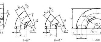
Below this text the figure shows the calculation diagram.
The radii of the neutral layers of each of the curved sections are calculated using the formula:
r ni
=((4* R i 2 - D 2 ) 0.5 +(4* R i 2 - d 2 ) 0.5)/4
The neutral layer is the surface closest to the center of the bending radius of the pipe material during bending compresses, and beyond which from the center of the bending radius it stretches.
The length of curved sections when bending a pipe is determined by the formula:
li =π *α i /180*r ni
Here the angle α i
must be in degrees.
The total length of the development is calculated by summing the lengths of straight and curved sections:
L
= ∑( L i + l i )
Program for calculating the length of development in Excel when bending pipes.
To perform calculations we use MS Excel.
You can use the Calc spreadsheet processor from the free Apache OpenOffice or LibreOffice .
Initial data:
Let's assume that in the example under consideration, the part consists of three straight and two curved sections (as in the diagram above).
1.
We write down the outer diameter of the pipe
D
in millimeters
to cell D4: 57,0
2.
the value of the internal diameter of the pipe
d
in millimeters
to cell D5: 50,0
Attention!!!
If the development length of a solid round bar is calculated, then d =0!
3.
the length of the first straight section
L 1
in millimeters
to cell D6: 200,0
4.
the axial bend radius of the first curved section
R 1
in millimeters
to cell D7: 300,0
5.
the bending angle of the first curved section
α 1
in degrees
to cell D8: 90,0
6.
the length of the second straight section of the part
L 2
in millimeters
to cell D9: 100,0
7.
the axial bend radius of the second curved section
R 2
in millimeters
to cell D10: 200,0
8.
the bending angle of the second curved section
α 2
in degrees
to cell D11: 135,0
9.
the length of the third straight section of the part
L 3
in millimeters
to cell D12: 300,0
10-15.
Entering the initial data into Excel for our example is complete. We leave cells D13…D18 empty.
The program allows you to calculate the development of parts containing up to five straight sections and up to four curved ones. Bending a pipe with a large number of sections requires a slight modernization of the program to calculate the development.
Calculation results:
16.
the length of the first curved section
L 1
in millimeters
in cell D20: =IF(D7=0;0;PI()*D8/180*((4*D7^2-$D$4^2)^0.5+(4*D7^2-$D$5 ^2)^0.5)/4) =469,4
17.
the length of the second curved section
L 2
in millimeters
in cell D21: =IF(D10=0;0;PI()*D11/180*((4*D10^2-$D$4^2)^0.5+(4*D10^2-$D$5 ^2)^0.5)/4) =467,0
18-19.
Since in the example under consideration there are no third and fourth curved sections, then
in cell D22: =IF(D13=0;0;PI()*D14/180*((4*D13^2-$D$4^2)^0.5+(4*D13^2-$D$5 ^2)^0.5)/4) =0,0
in cell D23: =IF(D16=0;0;PI()*D17/180*((4*D16^2-$D$4^2)^0.5+(4*D16^2-$D$5 ^2)^0.5)/4) =0,0
20.
The total length of the part development
L
in millimeters is summed up
in cell D24: =D6+D9+D12+D15+D18+D20+D21+D22+D23 =1536,3
The development length of the curved pipe was calculated using MS Excel.
Application area
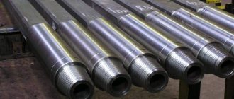
The high strength and low specific weight of seamless steel pipes make them in demand in many economic sectors. When constructing pipelines intended to move gases and liquids under high pressure, most bends are used without longitudinal seams.
Mining of oil and gas
In the gas and oil production sectors, thick pipes are used for transporting gas and liquid media over long distances, as well as for drilling. At great depths of excavation, the risks of increased soil pressure and rock shifts increase, which requires the use of a particularly strong casing structure. Seamless channels with reliable walls, made of high-quality alloys, will ensure trouble-free operation of drilling equipment.
Arrangement of hydraulic systems
Hydraulic systems are present in many lifting installations, important components of automobiles, and are used in industry and construction. Their work is distinguished by extreme temperature and high pressure force. Thick-walled steel pipes, which have a large margin of safety, successfully withstand these conditions.
Chemical industry
In the chemical industry, pipes with both thick and thin walls are used. Durable, thick-walled ones are used for transporting gases and toxic substances where there is high pressure. Thin-walled tubes are actively used in laboratories and medical instruments.
Energy production
Power plants are characterized by constant changes in internal excess pressure and high ambient temperatures. In these extreme operating conditions, the use of thick-walled seamless pipelines is optimal.
Shipbuilding and aircraft manufacturing
In these industries, one of the main tasks of designers is to minimize the weight of the main product. For this purpose, materials are used that must be reliable in operation and have low weight. The highest tensile strength and light weight of the seamless pipe fully meet these requirements of aircraft and shipbuilders, so the products are widely used among them
TECHNOCOM | Online bending force calculator
The calculator for calculating the required force of a press brake allows you to calculate the required tonnage. Useful for technologists and engineers for a general study of the capabilities of their equipment or for selecting a press brake to perform certain bending parameters. Allows you to obtain general reference values in a matter of seconds without complex calculations, including for further selection of bending tools or placing bending orders.
Legend
F (force, tonnage), tons - the total required force for bending S (thickness), mm - thickness of the material (sheet) for bending V (opening), mm - opening of the matrix h (flange length), mm - minimum required length for a straight residual flange parts after bendingL (bending length), mm - main bending length of the part (parallel to the width of the press brake)R (radius), mm - internal bending radius TS (tensile strength) - tensile strength of the part material for bending
The main formula used for calculation is:
Bending force F = (1.42 x TS x S2 x L)/1000 x V Inner radius R = (5 x V) / 32
Attention!
This calculator is intended solely for obtaining indicative reference information and cannot be an effective tool for accurate calculations and preparation of technical specifications. To obtain accurate and reliable values, you must consult with specialists.
Bending force table for press brake
The table below displays the approximate reference force according to die opening, minimum flange, metal thickness and radius. This table is valid for 1 meter of structural steel
| V | H min | R | 0,5 | 0,8 | 1 | 1,2 | 1,5 | 1,8 | 2 | 2,5 | 3 | 3,5 | 4 | 4,5 | 5 | 6 | 7 | 8 | 9 | 10 | 12 | 15 | 18 | 20 |
| 6 | 5 | 1 | 2,5 | 6,5 | 10 | |||||||||||||||||||
| 8 | 6 | 1,3 | 2 | 5 | 8 | 11 | ||||||||||||||||||
| 10 | 7 | 1,7 | 1,5 | 4 | 6 | 9 | 13 | |||||||||||||||||
| 12 | 9 | 2 | 3 | 5 | 7 | 11 | 16 | |||||||||||||||||
| 15 | 12 | 2,7 | 4 | 6 | 9 | 13 | 16 | |||||||||||||||||
| 20 | 15 | 3,3 | 4 | 7 | 10 | 13 | 19 | |||||||||||||||||
| 26 | 18 | 4,2 | 5 | 7,5 | 10 | 14 | 21 | |||||||||||||||||
| 30 | 22 | 5 | 6,5 | 8 | 12 | 19 | 24 | |||||||||||||||||
| 32 | 23 | 5,4 | 7,5 | 11,6 | 17 | 23 | 30 | |||||||||||||||||
| 37 | 25 | 5,8 | 10 | 14,5 | 20 | 26 | 33 | |||||||||||||||||
| 42 | 29 | 6,7 | 13 | 17 | 23 | 29 | 35,5 | |||||||||||||||||
| 45 | 32 | 7,5 | 16 | 21 | 27 | 33 | 48 | |||||||||||||||||
| 50 | 36 | 8,3 | 19 | 24 | 30 | 43 | 58 | |||||||||||||||||
| 60 | 43 | 10 | 20 | 25 | 36 | 49 | 64 | |||||||||||||||||
| 70 | 50 | 11,5 | 21 | 31 | 42 | 55 | 69 | |||||||||||||||||
| 80 | 57 | 13,5 | 27 | 37 | 48 | 60 | 75 | |||||||||||||||||
| 90 | 64 | 15 | 32 | 42 | 54 | 66 | 95 | |||||||||||||||||
| 100 | 71 | 17 | 38 | 48 | 60 | 86 | 134 | |||||||||||||||||
| 130 | 93 | 22 | 37 | 46 | 66 | 103 | 149 | |||||||||||||||||
| 180 | 130 | 30 | 33 | 48 | 75 | 107 | 133 | |||||||||||||||||
| 200 | 145 | 33 | 43 | 67 | 97 | 119 | ||||||||||||||||||
| 250 | 180 | 42 | 54 | 77 | 95 |
www.technocom-rus.ru
How to make pipes from sheet metal yourself
Today we will tell you how to bend a pipe without a rolling machine. Needed to install a “potbelly stove”. In this case, a similar one comes out of the garage. You can, of course, buy it in rolled metal, but they don’t have a wall thickness of 1.5 mm, there are 3-4 mm and they are heavy. Therefore, the decision was to buy 1.5 mm sheet metal and bend it yourself. To do this we need a pipe on which we will bend it. We will twist metal onto it. Two tubes are welded at the ends. Insert a crowbar and twist on one side and the other. And sheet metal is welded here to fix it. In the video “Avramenko Garage” we will show how this happens.
Received it on the way out. The task is worth it. How to bend the edge, you can’t grab it at the end. Try using a hammer, mallet, bending, or simply cutting off the part that is not bent (just remove). Then we make a measuring rope. We measure what diameter is needed and make a measuring rope, say 30 cm. We measure. On the other side we make a mark and use a grinder to cut and remove a part. Next piece of pipe. When everything has been cut and removed, we weld the seam and get a 1.5 mm metal pipe without using sheet bending machines.
Read also: Pressure reducer for a gas cylinder
The next one, the same distance, is cut off and welded again. They will be welded into one long pipe. The end result of a welded finished product. This is one part, as you can see, the second and third, so gain length. In this simple way you can make the pipe you need at home. Thank you for your attention.
If you have straight arms, bending tin and making pipes out of it is quite simple!
Making a pipe from tin with your own hands is an excellent alternative to buying an expensive drain or ventilation casing. In practice, the savings turn out to be colossal, and if you consider that having mastered the technology, you can literally “stamp” pipes of any (okay, almost any) diameter - then it’s definitely worth reading my tips and at least trying to implement them in practice!
Below I will talk about what we need to form the pipe, and also describe the algorithm by which I have been successfully bending tin products for five years.
Device for marking pipes. Calculation and production of a template - Equipment
In large procurement workshops, marking and cutting of pipes is carried out on a marking and cutting unit, which makes it possible to obtain pipeline parts with a tolerance of ± 1 mm.
In small procurement workshops and at the installation site, pipe marking is carried out on marking racks using conventional marking and measuring tools: rulers, tape measures, scribers, templates, etc.
Marking the pipe consists of determining its blank length and drawing the necessary axes. Having marked the pipe for cutting, the beginnings of all bends, holes for inserting taps and tees are marked on it.
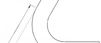
To manufacture a bent bend and determine the length of the workpiece, the radius (R) and angle (a) of the bend of the pipe, the length of the free ends or the length of the straight section between the bends must be known. The length of the workpiece (Fig. 1) is determined by the formula
Where LTotal is the length of the workpiece, m;
L= π/180*αR – length of the curved part, m;
L1 = L – S – length of the straight section, m;
L2 = L1-S-length of the second straight section, m; .
Figure 1. Marking the pipe for bending
- a – marking of the outlet;
- b – pipeline section.
When two pipes intersect, the cutting tee is marked using a device that is made on a sheet of thick paper. First, the intersection of two pipes is drawn in two projections and in full size, as shown in Fig. 2. A semicircle is built on the embedded part of the pipe, which is usually divided into six parts (points 1, 2, 3, 4, 5, 6). Straight lines parallel to the axis of the pipe are drawn through these points. On the second projection, similar constructions are made, straight lines are drawn until they intersect with the contour of the pipe into which the insertion needs to be made (points 0, 1, 2, 3). Drawing parallel lines from these points, as shown in the figure, we obtain points 0l, 1l, 2l, 3l, 4l, 5l, 6l.
Rice. 5. Marking the intersection of two pipes
Cutting methods
The following methods are used to process such materials:
- thermal cutting: use of a plasma or gas cutter, laser equipment;
- mechanical: use of a roller pipe cutter, grinder, hacksaw.
When choosing a cutting method, you should take into account the volume of work and the durability of the selected device and equipment.
Work technology
Step 1. Preparation
Instructions for making a pipe from tin begin with a description of the preparation of the workpiece:
Laying the material on the workbench
- On a workbench or other flat surface we roll out sheet metal, leveling it using mechanical action if necessary.
- We measure the length and width of the pipe by marking the material with chalk, marker or marker. When marking, we take into account that the width of the workpiece should be equal to the circumference of the pipe + 1.5...1.6 cm for forming a seam.
- We control the perpendicularity of the drawn lines using a square.
Cut to size
- We take scissors and make first a side and then a longitudinal cut. You need to cut strictly along the lines, trying not to make large indents. If the cut line “walks”, problems may arise at the stage of seam formation.
- Once again we level our workpiece. If necessary, tap the edges to remove waves and process them, removing burrs.
Step 2. Pipe Forming
Now we need to make a round pipe from the blank. And at the first stage we create a profile:
- On one side of the part we draw a fold line at a distance of 0.5 cm from the edge.
- On the other side we draw the same line at a distance of 1 cm.
Folding pattern
- We place the workpiece on a steel corner and bend the folds perpendicular to the plane of the sheet. To bend, use a mallet, adjusting the metal with pliers if necessary.
- I usually do this: first I grab the metal with pliers, forming a bend about 2-3 cm wide. After the direction of deformation has been set, I change the pliers to a mallet and continue working, using a steel template as a support.
- When working according to a template, we do not apply excessive force, otherwise we risk damaging the material and “scraping off” part of the protective coating,
- Next, we divide the bent fold 1 cm wide in half along the width and repeat the fold. Now we need to bend a strip 0.5 cm wide parallel to the main workpiece.
Read also: Where to put ouzo in the apartment
- Now we form the pipe profile. We place the workpiece on the calibrating surface and tap it, first bending an arc, and then a full circle. The smoother it is, the better - there will be less fiddling around at the final stage of work.
Step 3. Processing the joint
Now we need to form a seam that will turn our workpiece into the actual pipe:
- We combine the folds, bent perpendicular to the main part, pressing them tightly against each other.
Pipe blank with bent seam
- We bend the horizontal part of the long fold so that it wraps around the combined parts.
- We lay the resulting three-layer structure on a workbench and carefully tap it, compacting it thoroughly. At the same time, we make sure that there are no distortions that will negatively affect the strength of the structure.
Strengthening the connection on the blank
- We bend the seam from the folds assembled together towards the pipe wall. We put the product on the calibration blank and tap the joint again. The resulting connection holds perfectly without any fasteners due to the plasticity of the sheet metal.
When producing large-diameter pipes that experience significant loads, the width of the folds can be increased and the joint further strengthened with rivets.