Sections
If, during a conditional section of an object, only that part of it that is in the secant plane is left, a section is obtained in its drawing sense.
Sections are divided into:
- being part of the cut;
- independent.
Among the independent ones there are:
- Taken out. They are drawn behind the outline of the main view. They are recommended by the standard as preferred.
- Overlaid. Placed directly on the drawing of the corresponding type or in its gap. Sometimes the design document becomes difficult to read.
Superimposed sections
The system of location, designation and naming of sections is similar to the system of designation of sections
It is important to remember that lines indicating sections cannot intersect with drawing elements. The secant trace is displayed as a thick line with a break
Total tolerances of shape and location
Each of these parameters combines both permissible deviations. They arise as a result of the simultaneous manifestation of a change in geometric shape and the appearance of unevenness (roughness) of the treated surface. Therefore, using mathematical terminology, they say that the limit to which the difference between the standard and the real product should tend is considered the total tolerance of shape and location. The nature of the changes is determined by the method of comparison with the selected base objects. As such objects, proven structures or surfaces are chosen that can be considered standards, for example, various calibers.
Such tolerances are divided into the following categories:
- Beating. These include: radial, end, in a predetermined direction;
- All surface shapes.
Each of these categories has its own designation. The total runout tolerance is indicated by two oblique arrows in the form of vectors combined from below, directed from the lower left corner to the upper right. Comparison of shapes is made by combining both surfaces.
This field has specified geometric dimensions. It is oriented relative to the selected base so that the parallelism of the location can be checked. Examples of total tolerance indicate how much it is possible to change parameters without leading to rapid failure of the unit. This is especially true for mobile connections
Kinds
The preferred method for depicting three-dimensional products on a plane is orthogonal projection. The location of the depicted object is assumed to be between the conventional observer and the projection plane. To improve the readability of the image, a simplified approach is permitted. Therefore, the images in the drawings are not projection in the strict geometric sense of the word. They are called images on a plane. To obtain the main projections, the depicted part is placed in the center of an imaginary cube. Its edges will serve as projection planes.
Main types
As a result of the projection of the image of the object, a diagram of the main types of the product appears:
- front;
- on right;
- below;
- left;
- above;
- behind.
In technical drawing, the front view is considered the main one. It should give maximum information about the depicted detail. It is complemented by views from the left and from above (relative to the main one). These three types are called the main ones. The rest are considered auxiliary. Their images are constructed if important design information about a product of complex shape is not visible in the three main views.
In addition, to explain the structure of part of the part, local views are used, showing a fragment of the image of the main view. Such images are placed in unoccupied areas, inscribed in capital letters of the Cyrillic alphabet. On the main view, in the area where the fragment is located, there is an arrow showing the direction of the conditional view, as a result of which the local view appears. Such designs are limited by break lines drawn in the direction of the minimum element size.
In addition, additional types are used. They are built on planes placed at an angle to the main faces of the projection cube. They help to illustrate the location and structure of those parts of the object that are not visible or are not sufficiently presented in the main views, or their dimensions and configuration are distorted. The designation of additional species is carried out using letters of the Cyrillic alphabet.
Additional views
A thoughtful choice of local and additional views allows you to reduce the number of hatches when showing the internal structure of a part that is invisible on the main projections. The readability of the drawing, the relative position of its parts also improves, and the likelihood of its erroneous interpretation is reduced.
/
0,01
The cone runout tolerance relative to the hole axis A in the direction perpendicular to the cone generatrix is 0.01 mm
1 U//sh>
A
16 Total radial runout tolerance
| A/ | 0,1 | AB |
Tolerance for complete radial runout relative to the common axis of surfaces L and B - 0.1 mm
AND
17 Tolerance for total axial runout
| 0,1 |
Tolerance for complete end runout of the surface relative to the surface axis - 0.1 mm
18 Shape tolerance of a given profile
\G\\T0M
Shape tolerance of a given profile - 70.04 mm
| 1 | iD |
| □ |
Indication of form tolerances and
Type of admission
location symbol
Explanation
19 Shape tolerance of a given surface
Tolerance of the shape of a given surface relative to surfaces A, B, C - 70.1 mm
20 Total tolerance of parallelism and flatness
The total tolerance for parallelism and flatness of the surface relative to the base is 0.1 mm
21 Total perpendicularity and flatness tolerance
The total tolerance for perpendicularity and flatness of the surface relative to the base is 0.02 mm
22 Total flatness inclination tolerance
And
The total tolerance for inclination and flatness of the surface relative to the base is 0.05 mm
End of table B. 1
Notes
1 In the examples given, the tolerances of coaxiality, symmetry, positional, intersection of axes, the shape of a given profile and a given surface are indicated in diametrical terms.
It is allowed to indicate them in radius expression, for example:
| R0.0A | — | T/2 0.025 | A |
In previously issued documentation, tolerances for coaxiality, symmetry, and displacement of axes from the nominal location (positional tolerance), respectively indicated by the signs i— ; ; + or text in those
technical requirements should be understood as tolerances in radius terms.
2 Indication of tolerances of shape and location of surfaces in text documents or in the technical requirements of a graphic document should be given by analogy with the text of the explanations for the symbols of tolerances of shape and location given in this appendix.
In this case, the surfaces to which tolerances of shape and location apply or which are taken as the base should be designated with letters or their design names given.
It is allowed to indicate the @ sign instead of the words “dependent tolerance” and instead of indications before the numeric value of the characters 0 ; R; T; T/2 - text entry, for example “positional axis tolerance 0.1 mm in diametrical terms” or “symmetry tolerance 0.12 mm in radial terms.”
3 In the newly developed documentation, the entry in the technical requirements on the tolerances for ovality, cone-shape, barrel-shape and saddle-shape should, for example, be as follows: “Tolerance for ovality of surface A 0.2 mm (half difference in diameters).”
In technical documentation developed before January 1, 1980, the limit values of ovality, cone-shaped, barrel-shaped and saddle-shaped are defined as the difference between the largest and smallest diameters.
Bibliography
Basic norms of interchangeability. Product characteristics are geometric. Tolerances of shape, orientation, location and runout
UDC 744.43:006.354 MKS 01.080 T52 OKSTU 0002
Key words: design documentation, shape tolerance, location tolerance
Editor R.G. Goverdovskaya Technical editor V.N. Prusakova Corrector M.S. Kabashova Computer layout A.N. Zolotareva
Signed for publication on February 13, 2012. Format 60×84%. Offset paper. Arial typeface. Offset printing. Uel. oven l. 3.26. Academic ed. l. 2.70. Circulation 600 copies. Zach. 155.
, 123995 Moscow, Granatny lane, 4.
Typed on a PC.
Printed in the branch - type. "Moscow Printer", 105062 Moscow, Lyalin lane, 6.
GOST 2.307-68 ESKD. Drawing dimensions and maximum deviations
STATE STANDARD OF THE USSR UNION
Unified system of design documentation
APPLICATION OF DIMENSIONS AND LIMIT DEVIATIONS
GOST 2.307-68 (ST SEV 1976-79, ST SEV 2180-80)
STATE STANDARD OF THE USSR UNION
| Unified system of design documentation APPLICATION OF DIMENSIONS AND LIMIT DEVIATIONS Unified system for design documentation. Drawing of dimensions and limit deviations | GOST 2.307-68 (ST SEV 1976-79, ST SEV 2180-80 |
Date of introduction 01/01/71
This standard establishes the rules for drawing dimensions and maximum deviations on drawings and other technical documents for products from all sectors of industry and construction.
(Changed edition, Amendment No. 3).
1.1. The basis for determining the size of the depicted product and its elements are the dimensional numbers printed on the drawing.
The exception is the cases provided for in GOST 2.414-75; GOST 2.417-78; GOST 2.419-68, when the size of a product or its elements is determined from images made with a sufficient degree of accuracy.
The basis for determining the required accuracy of a product during manufacturing is the maximum dimensional deviations indicated in the drawing, as well as the maximum deviations of the shape and location of surfaces.
1.2. The total number of dimensions in the drawing should be minimal, but sufficient for the manufacture and control of the product.
1.3. Dimensions that cannot be made according to this drawing and are indicated for greater convenience in using the drawing are called reference.
1.4. Reference dimensions are on the drawing, and in the technical requirements they write: “* Dimensions for reference.” If all the dimensions in the drawing are for reference, they are not marked with the “*” sign, but in the technical requirements they write: “Dimensions for reference.”
On construction drawings, reference dimensions are noted and specified only in cases provided for in the relevant documents approved in the prescribed manner.
1.5. The following sizes are referenced:
a) one of the sizes of a closed dimensional chain. Maximum deviations of such dimensions are not indicated in the drawing (Fig. 1);
___________
*Dimensions for reference.
Crap. 1
b) dimensions transferred from the drawings of blank products (Fig. 2);
___________
*Dimensions for reference.
Crap. 2
c) dimensions that determine the position of the elements of the part to be processed on another part (Fig. 3);
___________
1* Dimensions for reference.
2** Process on the mating part (or on the part...).
Crap. 3
d) dimensions on the assembly drawing, which determine the limiting positions of individual structural elements, for example, piston stroke, valve rod stroke of an internal combustion engine, etc.;
e) dimensions on the assembly drawing, transferred from the drawings of parts and used as installation and connecting ones;
f) overall dimensions on the assembly drawing, transferred from the drawings of parts or being the sum of the dimensions of several parts:
g) dimensions of parts (elements) made of long, shaped, sheet and other rolled products, if they are fully determined by the designation of the material given in column 3 of the main inscription.
Notes:
1. The reference dimensions specified in subparagraphs b, c, d, f, g of this paragraph may be applied both with maximum deviations and without them
2. Installation and connecting dimensions are dimensions that determine the dimensions of the elements by which this product is installed at the installation site or connected to another product.
3. Dimensions are dimensions that determine the maximum external (or internal) outline of the product.
1.6. On the drawings of products in sizes that are technically difficult to control; put the “*” sign, and in the technical requirements the inscription “Provision dimensions” is placed. instr."
Note. This inscription means that the execution of the size specified in the drawing with a maximum deviation must be guaranteed by the size of the tool or the corresponding technological process.
In this case, the dimensions of the tool or the technological process are checked periodically during the manufacturing process of products.
The frequency of monitoring of a tool or technological process is established by the manufacturer together with the customer’s representative.
1.7. It is not allowed to repeat the dimensions of the same element in different images, technical requirements, title block and specifications. The exception is the reference dimensions given in paragraph 1.5 b and g.
If in the technical requirements it is necessary to give reference to the size marked on the image, then this size or the corresponding element is indicated by a letter, and in the technical requirements an entry similar to that shown in the drawing is placed. 4.
___________
1. Parallelism tolerance of the hole axes. A
and
B
0.05 mm.
2. Size difference B
on both sides no more than 0.1 mm.
Crap. 4
Dimensions may be repeated on construction drawings.
1.5-1.7. (Changed edition, Amendment No. 2).
1.8. Linear dimensions and their maximum deviations in drawings and specifications are indicated in millimeters, without indicating a unit of measurement.
For dimensions and maximum deviations given in the technical requirements and explanatory notes on the drawing field, units of measurement must be indicated.
(Changed edition, Amendment No. 3).
1.9. If the dimensions in the drawing must be indicated not in millimeters, but in other units of measurement (centimeters, meters, etc.), then the corresponding dimensional numbers are written down with the designation of the unit of measurement (cm, m) or indicated in the technical requirements.
In these cases, units of measurement may not be indicated on construction drawings if they are specified in the relevant documents approved in the prescribed manner
1.10. Angular dimensions and maximum deviations of angular dimensions are indicated in degrees, minutes and seconds with the designation of the unit of measurement, for example - 4°; 4°30 ‘
; 12°45
‘
30
«
; 0°30
‘
40
«
; 0 ° 18
‘
; 0 ° 5
‘
25
«
; 0°0
‘
30
«
; 30°±l°; 30°±10
‘
.
Crap. 5
Crap. 6
1.11. For dimensional numbers, simple fractions are not allowed, with the exception of sizes in inches.
1.12. The dimensions that determine the location of the mating surfaces are set, as a rule, from the structural bases, taking into account the possibilities of making and controlling these dimensions.
1.13. When the elements of an object (holes, grooves, teeth, etc.) are located on the same axis or on the same circle, the dimensions that determine their relative position are applied in the following ways:
from the common base (surface, axis) - according to the line. 5a and b;
setting the sizes of several groups of elements from several common bases - according to the drawing. 5c;
setting the dimensions between adjacent elements (chain) - according to the drawing. 6.
1.14. Dimensions on drawings are not allowed to be drawn in the form of a closed chain, except in cases where one of the dimensions is indicated as a reference (see Drawing 1).
On construction drawings, dimensions are applied in the form of a closed circuit, except for cases provided for in the relevant documents approved in the prescribed manner.
The dimensions that determine the position of symmetrically located surfaces of symmetrical products are applied as shown in Fig. 7 and 8.
Crap. 7
___________
*Dimensions for reference.
Crap. 8
(Changed edition, Amendment No. 2).
1.15. For all dimensions marked on the working drawings, maximum deviations are indicated.
It is allowed not to indicate maximum deviations:
a) for dimensions that define zones of different roughness of the same surface, zones of heat treatment, coating, finishing, knurling, notches, as well as the diameters of knurled and notched surfaces. In these cases, the sign “” is applied directly to such dimensions;
b) for the dimensions of parts of individually produced products specified with an allowance for fit.
On such drawings, the “*” sign is placed in close proximity to the indicated dimensions, and in the technical requirements the following is indicated:
“* Dimensions with allowance for fit up to detail. . . . . ",
“* Dimensions with allowance for fit according to drawing. . . . . ",
“* Dimensions with allowance for fit, according to the mating part.”
On construction drawings, maximum dimensional deviations are indicated only in cases provided for in the relevant documents approved in the prescribed manner.
1.16. When making working drawings of parts manufactured by casting, stamping, forging or rolling with subsequent machining of part of the surface of the part, indicate no more than one size in each coordinate direction, connecting the machined surfaces with surfaces not subject to machining (Fig. 9 and 10) .
Crap. 9
Crap. 10
(Changed edition, Amendment No. 2).
1.17. If an element is depicted at a deviation from the image scale, then the size number should be emphasized (Fig. 10a).
Crap. 10a
(Introduced additionally, Amendment No. 2).
2.1. Dimensions in the drawings are indicated by dimensional numbers and dimension lines.
2.2. When applying the size of a straight segment, the dimension line is drawn parallel to this segment, and extension lines are drawn perpendicular to the dimension lines (Fig. 11).
Crap. eleven
2.3. When applying the size of an angle, the dimension line is drawn in the form of an arc with the center at its vertex, and the extension lines are drawn radially (Fig. 12).
Crap. 12
2.4. When applying the size of a circular arc, the dimension line is drawn concentrically to the arc, and the extension lines are parallel to the bisector of the angle, and the sign “Ç” is placed above the dimension number (Fig. 13).
Crap. 13
It is allowed to place extension lines of the arc size radially, and if there are also concentric arcs, it is necessary to indicate which arc the size belongs to (Fig. 14).
Crap. 14
2.4a. When drawing dimensions of parts similar to those shown in Fig. 14a, dimension lines should be drawn in the radial direction, and extension lines should be drawn along circular arcs (Fig. 14a).
Crap. 14a
(Introduced additionally, Amendment No. 2).
2.5. The dimension line at both ends is limited by arrows resting on the corresponding lines, except for the cases given in paragraphs. 2.16, 2.17, 2.20 and 2.21, and when drawing a radius line limited by an arrow on the side of the defined arc or fillet.
In construction drawings, instead of arrows, it is allowed to use serifs at the intersection of dimension and extension lines, and the dimension lines must protrude beyond the outer extension lines by 1 . . . 3 mm.
2.6. In the cases shown in Fig. 15, the dimension and extension lines are drawn so that they, together with the measured segment, form a parallelogram.
Crap. 15
2.7. It is allowed to draw dimension lines directly to the lines of the visible contour, axial, center and other lines (Fig. 16 and 17).
Crap. 16
Crap. 17
2.8. It is preferable to apply dimension lines outside the outline of the image.
2.9. Extension lines should extend beyond the ends of the dimension line arrows by 1. . 5 mm.
2.10. The minimum distances between parallel dimension lines should be 7 mm, and between the dimension and contour lines - 10 mm and are selected depending on the size of the image and the saturation of the drawing.
(Changed edition, Amendment No. 2).
2.11. It is necessary to avoid intersections of dimension and extension lines (see Figure 16).
2.12. It is not allowed to use contour lines, axial, center and extension lines as dimension lines.
2.13. Extension lines are drawn from the lines of the visible contour, except for the cases specified in paragraphs. 2.14 and 2.15, and cases when, when drawing dimensions on an invisible contour, there is no need to draw an additional image.
2.14. The contour dimensions of the curved profile are applied as shown in Fig. 16 and 17.
2.15. If it is necessary to show the coordinates of the vertex of the rounded corner or the center of the rounding arc, then extension lines are drawn from the point of intersection of the sides of the rounded corner or the center of the rounding arc (Fig. 18).
Crap. 18
2.16. If a view or section of a symmetrical object or individual symmetrically located elements is depicted only up to the axis of symmetry or with a break, then the dimension lines related to these elements are drawn with a break, and the break of the dimension line is made further than the axis or break line of the object (Fig. 19).
Crap. 19
In construction drawings in such cases, all dimensions may be indicated only up to the axis of symmetry, and the dimension lines at the intersection with the axis of symmetry may be limited by a serif cross.
2.17. Dimension lines may be drawn with breaks in the following cases:
a) when indicating the size of the diameter of a circle, regardless of whether the circle is depicted completely or partially, while the break of the dimension line is made further than the center of the circle (Fig. 20);
Crap. 20
b) when drawing dimensions from a base not shown in this drawing (Fig. 21).
Crap. 21
2.18. When depicting a product with a gap, the dimension line is not interrupted (Fig. 22).
Crap. 22
2.19. The values of the elements of the dimension line arrows are selected depending on the thickness of the lines of the visible contour and they are drawn approximately the same throughout the entire drawing. The shape of the arrow and the approximate relationship of its elements are shown in Fig. 23.
Crap. 23
(Changed edition, Amendment No. 2).
2.20. If the length of the dimension line is not sufficient to place arrows on it, then the dimension line is continued beyond the extension lines (or, accordingly, beyond the contour, axial, center, etc.) and the arrows are drawn as shown in Fig. 24.
Crap. 24
2.21. If there is not enough space for arrows on dimension lines arranged in a chain, the arrows can be replaced with serifs applied at an angle of 45° to the dimension lines (Fig. 25), or clearly marked dots (Fig. 26).
Crap. 25
Crap. 26
2.22. If there is not enough space for the arrow due to a closely located contour or extension line, the latter can be interrupted (Fig. 24 and 27).
Crap. 27
2.23. Dimensional numbers are applied above the dimension line, as close as possible to its middle (Fig. 28).
Crap. 28
2.24. When applying a diameter size inside a circle, the dimensional numbers are shifted relative to the middle of the dimensional lines.
2.25. When drawing several parallel or concentric dimension lines at a short distance from each other, it is recommended to place the dimension numbers above them in a checkerboard pattern (Fig. 29).
Crap. 29
2.26. Dimensional numbers of linear dimensions with different inclinations of dimension lines are placed as shown in figure 30.
Crap. thirty
If it is necessary to apply a size in the shaded area, the corresponding size number is applied on the shelf of the leader line (Fig. 31).
Crap. 31
2.27. Angular dimensions are applied as shown in Fig. 32. In the area located above the horizontal center line, dimensional numbers are placed above the dimensional lines on the side of their convexity; in the area located below the horizontal center line - from the side of the concavity of the dimension lines. It is not recommended to apply dimensional numbers in the shaded area. In this case, the dimensional numbers are indicated on horizontally applied shelves.
Crap. 32
For small corners with a lack of space, dimensional numbers are placed on the shelves of leader lines in any zone (Fig. 33).
Crap. 33
2.28. On construction drawings, it is allowed to apply linear and angular dimensional numbers and inscriptions without shelves of leader lines.
2.29. If there is not enough space above the dimension line to write the size number, then the dimensions are applied as shown in Fig. 34; if there is not enough space to apply the arrows, then they are applied as shown in the diagram. 35.
Crap. 34
Crap. 36
The method of applying the dimensional number at different positions of the dimensional lines (arrows) in the drawing is determined by the greatest ease of reading.
2.30. Dimensional numbers and maximum deviations are not allowed to be divided or crossed by any drawing lines. It is not allowed to break the contour line to apply the dimensional number and apply dimensional numbers at the intersection of dimensional, center or center lines. At the place where the dimension number is applied, the axial, center and hatch lines are interrupted (Fig. 36 and 37).
Crap. 36
Crap. 37
2.29, 2.30. (Changed edition, Amendment No. 2).
2.31. It is recommended to group dimensions related to the same structural element (groove, protrusion, hole, etc.) in one place, placing them in the image in which the geometric shape of this element is shown most fully (Fig. 38).
Crap. 38
2.32. When applying a radius size, place a capital letter R
.
2.33. If, when drawing the size of the radius of an arc of a circle, it is necessary to indicate the size that determines the position of its center, then the latter is depicted as the intersection of center or extension lines.
If the radius is large, the center can be brought closer to the arc; in this case, the radius dimension line is shown with a bend at an angle of 90 ° (Fig. 39).
Crap. 39
2.34. If it is not necessary to indicate the dimensions that determine the position of the center of the circular arc, then the radius dimension line may not be brought to the center and may be shifted relative to the center (Fig. 40).
Crap. 40
2.35. When drawing several radii from one center, the dimension lines of any two radii are not placed on the same straight line (Fig. 41).
crap. 41
If the centers of several radii coincide, their dimension lines may not be brought to the center, except for the extreme ones (Fig. 41a).
Crap. 41 a
2.36. The dimensions of the outer rounding radii are applied as shown in Fig. 42, internal fillets - to hell. 43.
Crap. 42
Crap. 43
Rounding radii, the size of which on the drawing scale is 1 mm or less, are not shown in the drawing and their dimensions are indicated as shown in Fig. 43a.
Crap. 43a
The method of applying dimensional numbers at different positions of dimensional lines (arrows) in the drawing is determined by the greatest ease of reading. Dimensions of identical radii may be indicated on a common shelf, as shown in Fig. 43b:
Crap. 43b
If the radii of fillets, bends, etc. are the same throughout the entire drawing or one radius is predominant, then instead of plotting the dimensions of these radii directly on the image, it is recommended to make an entry in the technical requirements like: “Fillet radii 4 mm”; “Internal bend radii 10 mm”; “Unspecified radii 8 mm”, etc.
2.35, 2.36. (Changed edition, Amendment No. 2).
2.37. When indicating the diameter size (in all cases), the sign “Æ” is placed before the size number.
2.38. Before the dimensional number of the diameter (radius) of the sphere, the sign Æ ( R
) without the inscription “Sphere” (Fig. 44). If it is difficult to distinguish a sphere from other surfaces in a drawing, then the word “Sphere” or the sign O can be written before the dimension number of the diameter (radius), for example, “Sphere Æ 18, OR12”.
The diameter of the sphere sign is equal to the size of the dimensional numbers in the drawing.
Crap. 44
2.39. The dimensions of the square are applied as shown in Fig. 45, 46 and 46a.
Crap. 45
Crap. 46
Crap. 46a
The height of the □ sign must be equal to the height of the dimensional numbers on the drawing.
2.38, 2.39 (Changed edition, Amendment No. 2).
2.40. Before the dimensional number characterizing the taper, the sign “<” is applied, the acute angle of which should be directed towards the apex of the cone (Fig. 47).
Crap. 47
The cone sign and taper as a ratio should be marked above the center line or on the shelf of the leader line.
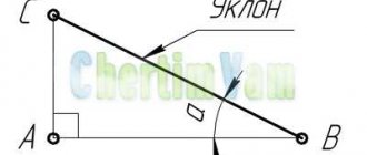
2.41. The surface slope should be indicated directly next to the image of the slope surface or on the shelf of the leader line in the form of a ratio (Fig. 48a), as a percentage (Fig. 48b) or in ppm (Fig. 48c). Before the dimensional number that determines the slope, a “<” sign is applied, the acute angle of which should be directed towards the slope.
Crap. 48
2.42. Markings of levels (height, depth) of a structure or its element from any reference level, taken as “zero” in the view and section, are placed on extension lines (or on contour lines) and are indicated by the sign “¯” made by solid thin lines, the length of the strokes is 2 - 4 mm at an angle of 45° to the extension line or contour line (Fig. 49a), in the top view they should be applied in a frame directly on the image or on the leader line (Fig. 49b), or as shown in Fig. 49a.
Crap. 49
Level marks are indicated in meters accurate to the third decimal place without indicating the unit of measurement.
2.43. The dimensions of the chamfers at an angle of 45° are applied as shown in Fig. 50.
Crap. 50
It is allowed to indicate the dimensions of a chamfer not shown in the drawing at an angle of 45°, the size of which in the drawing scale is 1 mm or less, on the shelf of a leader line drawn from the edge (Fig. 50a).
Crap. 50a
The dimensions of chamfers at other angles are indicated according to the general rules - linear and angular dimensions (Fig. 51a and b) or two linear dimensions (Fig. 51c).
Crap. 51
2.40-2.43. (Changed edition, Amendment No. 2).
2.44. The dimensions of several identical elements of the product, as a rule, are applied once, indicating the number of these elements on the shelf with a leader line (Fig. 52a).
It is allowed to indicate the number of elements, as shown in Fig. 52b.
Crap. 52
2.45. When applying the dimensions of elements evenly spaced around the circumference of the product (for example, holes), instead of the angular dimensions that determine the relative position of the elements, only their number is indicated (Fig. 53-55).
Crap. 53
Crap. 54
Crap. 55
2.46. The dimensions of two symmetrically located elements of the product (except for holes) are applied once without indicating their number, grouping, as a rule, all dimensions in one place (Fig. 56 and 57).
Crap. 56
___________
*Dimensions for reference.
Crap. 57
The number of identical holes is always indicated in full, and their sizes are indicated only once.
(Changed edition, Amendment No. 2).
2.47. When applying dimensions that determine the distance between evenly spaced identical elements of a product (for example, holes), it is recommended, instead of dimensional chains, to apply the size between adjacent elements and the size between extreme elements in the form of the product of the number of spaces between the elements and the size of the gap (Fig. 58).
Crap. 58
2.47a. It is allowed not to indicate on the drawing the dimensions of the radius of the arc of a circle of mating parallel lines (Fig. 58a).
Crap. 58a
(Introduced additionally, Amendment No. 2).
2.48. With a large number of dimensions applied from a common base, it is allowed to apply linear and angular dimensions, as shown in Fig. 59 and 60, while drawing a general dimension line from o and dimension numbers are applied in the direction of the extension lines at their ends.
Crap. 59
Crap. 60
2.48a. The dimensions of the diameters of a cylindrical product of complex configuration can be applied as shown in Fig. 60a.
Crap. 60a
(Introduced additionally, Amendment No. 2).
2.49. If there are a large number of similar elements of the product, unevenly located on the surface, it is allowed to indicate their dimensions in a summary table, using the coordinate method of drawing holes with their designation in Arabic numerals (Fig. 61), or designating similar elements in capital letters (Fig. 61a).
Crap. 61
Crap. 61 a
| Hole designation | Col. | Size, mm |
| A | 2 | 3 |
| B | 4 | 6,5 |
2.50. Identical elements located in different parts of the product (for example, holes) are considered as one element if there is no gap between them (Fig. 62a) or if these elements are connected by thin solid lines (Fig. 62b).
In the absence of these conditions, indicate the full number of elements (Fig. 62c).
Crap. 62
2.51. If identical elements of the product (for example, holes) are located on different surfaces and are shown in different images, then the number of these elements is recorded separately for each surface (Fig. 63).
Crap. 63
It is allowed to repeat the dimensions of identical elements of a product or their groups (including holes) lying on the same surface only if they are significantly removed from each other and are not related to each other in size (Fig. 64 and 65).
Crap. 64
Crap. 65
2.49-2.51. (Changed edition, Amendment No. 2).
2.52. If the drawing shows several groups of holes of similar sizes, it is recommended to mark the same holes with one of the symbols shown in the drawing. 66. It is allowed to use other symbols.
Crap. 66
The holes are indicated by symbols in the image, which shows the dimensions that determine the position of these holes.
On construction drawings, it is allowed to outline identical groups of holes with a solid thin line with an explanatory inscription.
2.53 When designating identical holes with conventional signs, the number of holes and their sizes may be indicated in the table (Figure 67).
Crap. 67
(Changed edition, Amendment No. 2).
2.54. When depicting a part in one projection, the size of its thickness or length is applied as shown in Fig. 68.
Crap. 68
2.55. The dimensions of a rectangular part or hole can be indicated on the leader line shelf by the dimensions of the sides through the multiplication sign. In this case, the size of the side of the rectangle from which the leader line is drawn should be indicated in the first place (Fig. 68a).
Crap. 68a
(Changed edition, Amendment No. 2).
3.1. Maximum dimensional deviations should be indicated immediately after the nominal dimensions. Maximum deviations of linear and angular dimensions of relatively low accuracy may not be indicated directly after the nominal dimensions, but may be specified by a general entry in the technical requirements of the drawing, provided that this entry unambiguously defines the values and signs of the maximum deviations.
A general record of maximum deviations of dimensions with unspecified tolerances must contain symbols of maximum deviations of linear dimensions in accordance with GOST 25346-89 (for deviations by qualifications) or in accordance with GOST 25670-83 (for deviations by accuracy classes). Symmetrical maximum deviations assigned according to qualifications should be indicated by indicating the qualification number.
Designations of one-sided maximum deviations by quality, assigned only for round holes and shafts (option 4 according to GOST 25670-83) are supplemented with a diameter sign (Æ).
Examples of general records corresponding to options in accordance with GOST 25670-83 for grade 14 and (or) accuracy class “medium” are given in table. 1:
Table 1
| Option number | Example of writing with symbols |
| 1. | N 14, |
| 2. | + t2, — t2 , |
| 3. | or |
| 4. | ÆN 14, Æ |
Notes:
1. It is allowed to supplement entries about unspecified maximum deviations of dimensions with explanatory words, for example, “Unspecified maximum deviations of dimensions: N
14,
h
14, ».
2. If the technical requirements in the drawing consist of one paragraph containing an entry about unspecified maximum dimensional deviations, or this entry is given in text documents, then it must be accompanied by explanatory words, for example, “Unspecified maximum dimensional deviations".
(Changed edition, Amendment No. 2).
3.la. Unspecified maximum deviations of radii of curvature, chamfers and angles are not specified separately, but must correspond to those given in GOST 25670-83 in accordance with the quality or accuracy class of unspecified maximum deviations of linear dimensions.
If all maximum deviations of linear dimensions are indicated immediately after the nominal dimensions (there is no general entry), then unspecified maximum deviations of the radii of roundings, chamfers and corners must correspond to those given in GOST 25670-83 for qualifications from 12 to 16 and are not specified in the drawing.
(Introduced additionally, Amendment No. 2).
3.2. Maximum deviations of linear dimensions are indicated in the drawings by symbols of tolerance fields in accordance with GOST 25346-89, for example: 18 N
7, 12
e
8 or numerical values, for example: 18+0.018, or symbols of tolerance fields indicating their numerical values on the right in parentheses, for example: 18
N
7(+0.018), 12
e
8.
It is allowed to indicate numerical values of maximum deviations in the table (Table 2), located on the free field of the drawing.
table 2
mm
| Size | Prev. off |
| 18N 7 | +0,018 |
| 12 e 8 | -0,032 -0,059 |
When indicating nominal dimensions with letter designations, tolerance fields must be indicated after a dash, for example, D
-H
11.
3.3. When indicating maximum deviations using symbols, it is also necessary to indicate their numerical values in the following cases:
a) when assigning maximum deviations (established by standards for tolerances and fits) of dimensions not included in the series of normal linear dimensions according to GOST 6636-69, for example: 41.5 18 N
7(+0,025),
b) when assigning maximum deviations, the symbols of which are not provided in GOST 25347-82, for example, for a plastic part with maximum deviations in accordance with GOST 25349-88 (Fig. 69);
Crap. 69
c) when assigning maximum deviations of the dimensions of ledges with an asymmetrical tolerance field (Fig. 70, 71);
Crap. 70
Crap. 71
d) (Deleted, Amendment No. 2).
3.4. Maximum deviations of angular dimensions are indicated only by numerical values (Fig. 72).
Crap. 72
3.5. When recording maximum deviations in numerical values, the upper deviations are placed above the lower ones. Maximum deviations equal to zero are not indicated, for example: ; ; 60+0.19; 60-0.19.
With a symmetrical arrangement of the tolerance field, the absolute value of the deviations is indicated once with a sign ±,
in this case, the height of the numbers defining the deviations must be equal to the height of the font of the nominal size, for example: 60±0.23.
3.6. Maximum deviations, indicated by numerical values expressed as a decimal fraction, are written down to the last significant digit inclusive, equalizing the number of digits in the upper and lower deviations by adding zeros, for example: ;
3.7. The maximum deviations in the dimensions of the parts shown in the assembly drawing are indicated in one of the following ways:
a) in the form of a fraction, the numerator of which indicates the symbol of the hole tolerance field, and the denominator - the symbol of the shaft tolerance field, for example: 50 or 50 N
11/
h
11 (Fig
.
73a);
b) in the form of a fraction, the numerator of which indicates the numerical values of the maximum deviations of the hole, and the denominator - the numerical values of the maximum deviations of the shaft (Fig. 73b);
Crap. 73
b1) in the form of a fraction, in the numerator of which the symbol of the tolerance field of the hole is indicated, with its numerical value indicated on the right in parentheses, and in the denominator - the symbol of the tolerance field of the shaft, with its numerical value indicated on the right in parentheses (Fig. 73c);
c) in the form of a record in which the maximum deviations of only one of the mating parts are indicated. In this case, it is necessary to explain which part these deviations relate to (Fig. 74).
_____________
*Dimensions for reference.
crap. 74
3.8. When different maximum deviations are assigned for surface areas with the same nominal size, the boundary between them is drawn with a solid thin line, and the nominal size is indicated with the corresponding maximum deviations for each area separately (Fig. 75).
crap. 75
The boundary line between areas should not be drawn through the shaded part of the image (Fig. 75a).
Crap. 75a
3.2-3.8. (Changed edition, Amendment No. 2).
3.9. If it is necessary to limit fluctuations in the size of identical elements of one part within part of the tolerance field (Fig. 76a) or it is necessary to limit the amount of accumulated error in the distance between repeating elements (Fig. 76b), then these data are indicated in the technical requirements.
______________ Maximum distance deviations
* Size difference 0.1 mm. between any non-adjacent teeth
±0.1 mm.
Crap. 76
3.10. When it is necessary to indicate only one limiting size (the second is limited in the direction of increase or decrease by some condition), after the size number indicate max or min, respectively (Fig. 77).
It is also possible to indicate maximum dimensions on assembly drawings for gaps, interference, backlash, etc., for example: “The axial displacement of the cam must be maintained within 0.6-1.4 mm.”
Crap. 77
3.11. The maximum deviations of the location of the hole axes can be specified in two ways:
a) positional tolerances of the hole axes in accordance with the requirements of GOST 2.308-79;
b) maximum deviations of dimensions coordinating the axes (Fig. 78 - 80).
Crap. 78
1. Limit deviations of dimensions between the axes of any two holes. ±0.35 mm.
2. Displacement of axes from plane A
no more than 0.18 mm
Crap. 79
Maximum deviations of dimensions diagonally between the axes of any two holes. ±0.5 mm.
Damn 80
If the tolerances for the location of the axes are dependent, then after the maximum deviations of the dimensions coordinating the axes, the sign of the dependent tolerance M should be indicated
(Changed edition, Amendment No. 2).
INFORMATION DATA
1. DEVELOPED AND INTRODUCED by the Committee of Standards, Measures and Measuring Instruments under the Council of Ministers of the USSR
PERFORMERS
V. R. Verchenko, Yu. I. Stepanov, Ya. G. Starozhilets, B. Ya. Kabakov, L. V. Matveev, P. N. Kolkin, V. N. Vzorov, M. G. Aranovsky, E. M. Koliseyeva.
2. APPROVED AND ENTERED INTO EFFECT by the Decree of the Committee of Standards, Measures and Measuring Instruments under the Council of Ministers of the USSR in December 1967.
3. The standard fully complies with ST SEV 1976-79 and ST SEV 2180-80.
4. INSTEAD OF GOST 3458-59, GOST 9171-59, GOST 5292-60 regarding section.
III
5. REFERENCED REGULATIVE AND TECHNICAL DOCUMENTS
| Designation of the referenced technical document | Item number, listing |
| GOST 2.308-79 | 3.11, item a |
| GOST 2.414-75 | 1.1 |
| GOST 2.417-78 | 1.1 |
| GOST 2.419-68 | 1.1 |
| GOST 6636-69 | 3.3, item a |
| GOST 25346-89 | 3.1, 3.2 |
| GOST 25347-82 | 3.3, item b |
| GOST 25349-88 | 3.3, item b |
| GOST 25670-83 | 3.1, 3.1a |
6. REISSUE (December 1990) with Amendments 2, 3, approved in June 1983; Fast. 2650 dated June 22, 1983, September 1987 (IUS 9-83, 12-87).
CONTENT
| 1. Basic requirements. 1 2. Applying dimensions. 6 3. Drawing of maximum dimensional deviations. 22 |
Basic provisions
Even small bevels of sharp edges present in the project must be indicated in the technical documentation if such smoothing has a functional significance. However, this is often not necessary, since according to ESKD (Unified System of Design Documentation) all sharp edges formed as a result of manufacturing and in contact with a person must be dulled. Depending on the scale and features of the node, it is possible to show the chamfer in several ways.
Typically, a chamfer in a drawing is indicated using dimension lines; the use of contour or axial lines for this is prohibited by GOST standards.
The main criterion is the possibility of convenient reading, so that during manufacturing there is no doubt about which unit the parameter belongs to. In this case, two numerical values must be indicated: the first is the width of the bevel in mm, the second is the angle relative to the main axis of the entire mechanism or a separate element. When depicting symmetrical chamfers at the same angle on one part, it is possible to separately indicate the first value, and depict the second by the value of the obtuse angle that they form. A chamfer is often used to designate a chamfer in a drawing with two linear dimensions, each of which indicates the size of the cut in different planes.
The designation of a chamfer in a drawing in accordance with GOST is made in a standard font and only in one view; duplication in other projections is not required. In this case, the dimensions of the external chamfers are applied on the main side, and the internal ones are indicated only on the section.
Chamfer designation in the drawing
The dimensions of the chamfers in the drawing, at an angle of 45°, are marked with dimension lines or on the shelf of a leader line; if its size on the scale of the drawing is 1 mm or less, the chamfer is displayed as shown in the image below on the right side.
Designation of a chamfer on the drawing at an angle of 45°
Chamfers with an angle not equal to 45° are indicated by linear and angular dimensions or two linear dimensions.
Designation of a chamfer with an angle not equal to forty-five degrees
A chamfer is nothing more than an element of a part. The word chamfer owes its origin to the French word “ faccete ,” which means beveled parts of corners, edges, etc. The main part of chamfers is intended to blunt sharp corners in order to ensure the safety of subsequent technological operations or operation of products and mechanisms.
On technical drawings, chamfers and their geometric parameters are indicated in cases where it is necessary to clearly indicate its presence due to a technical solution. In other cases, chamfers or other edge shapes are not specified, but must be blunted .
Mainly, as mentioned above, chamfers are intended to ensure safety during further interaction between a person and the products of his production activities, but in some cases they are needed as decorative elements introduced by designers into the composition of the product.
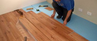
Bevels are very often used in the woodworking industry. The presence of chamfers here, combined with roundings that turn into fillets and back, combine very well with flat surfaces and give the product a finished appearance. Even the presence of a simple chamfer on any part visually gives it volume, not to mention shaped chamfers with changing cutting trajectories and inclination angles.
When finishing mirrors, decorative chamfers are made along the edges, in the form of small bevels of the edges. These kinds of edges are obtained as a result of grinding with a special diamond tool, on machines designed for carrying out such types of work, with abundant cooling. Edges processed in this way are called “ beveled ”. When making doors, or any other parts of the interior, glazing elements are used in the form of small tiles of a given size with a bevel. In combination with noble wood, they create a composition that gives a special solemn look and an atmosphere of comfort.
There are chamfers with a fairly gentle bevel, which allow the parts to perform functions that ensure guaranteed engagement or engagement with the mating components of assemblies and mechanisms.
In internal combustion engines, gas timing is an important determining part of the operation of the system as a whole. To realize the conditions of gas exchange, the inlet and outlet openings must open and close strictly in a certain order and ensure effective gas exchange. The timely supply of the combustible mixture and the release of exhaust gases is carried out by valves, which are driven by the kinematic elements of the mechanisms. One of the components of the valve is the sealing chamfer; it is entrusted with the important function of guaranteed shutoff and ensuring the unhindered release of gases.
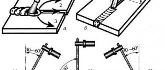
For high-quality metal welding, when connecting steel sheets exceeding the cross-sectional size of six or eight millimeters, technological chamfers are usually removed. There are two ways to prepare edges for welding - heat treatment or mechanical. Recently, edge preparation is most often used by the chipping method, in which the metal is displaced under the influence of tangential stresses. Such operations are performed by special machines with a system of guide rollers and a gripping round tool driven through a gearbox from an electric motor. The use of such mechanisms can significantly speed up preparatory work. The edge processing machine, "SNR - 12" from Spain, is an effective tool of this type.
Shape tolerances
This type of permitted deviation is caused by processing inaccuracies that occur due to the actual capabilities of the processing equipment.
These include:
- straightforwardness;
- planes;
- mismatch of the circle shape (these include: roundness; ovality tolerance);
- change in the shape of a cylinder - cylindricity tolerance.
The first category includes the following deviations:
- the shape of the processed surface (the planar pattern is disrupted, the radius of the machined shaft changes, the geometry of figures with flat edges is disrupted);
- the parallelism and perpendicular arrangement of surfaces between each other or adjacent parts is disrupted;
- different roughness appears along the length, cross-section, and circumference.
The parameter values are assessed by comparing the nominal surface (indicated in the drawing) and the real one (obtained on machines of a given accuracy class). The resulting deviations allow us to calculate the required tolerance.
A change in the radius of the finished product relative to that specified in the drawing is called a violation of roundness. To prevent possible negative consequences during operation, a roundness tolerance is introduced. When examining a part in one of the planes, the required tolerance of the longitudinal section profile is determined.
The nature of the mutual curvature of the arrangement of planes is divided into the following types:
- general parallelism (compared to a line directed along the surface);
- perpendicularity and intersection of axes (the preservation of a right angle throughout the entire surface is checked);
- tilt;
- symmetry (relative to the selected axis).
The flatness tolerance determines the amount of permitted deviation from the designated level. The main characteristic is the so-called tolerance zone. It is designated in a selected area, which is located between planes for which strict parallelism parameters must be observed. The distance to the surface is determined by existing standards. Monitoring the deviation of these parameters from those specified in the drawing is indicated on the profilogram.
How welding seams are shown on the drawings
The requirements for the development of working documentation and the symbols of welds on the drawings are regulated by the unified system of design documentation (ESKD).
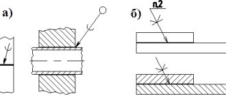
Regardless of the welding method, two main types of lines are used to indicate welds in the drawing:
- solid - for external visible joints;
- dashed (dotted) – for invisible connections.
In the photo below you can see which line represents a visible weld in the drawing and an invisible one.
In both cases, there must be an extension line with an arrow indicating the location of the seam. If the arrow points to a visible joint, then the symbol is placed above it, when an invisible one is placed below it.
When a joint is made by several passes superimposed on each other, it is called a multi-pass weld; the number of passes is indicated in the drawing when it is designated.
All connecting joints can be made:
- one-sided. Formed when welding parts on only one side of the surface, they are represented by the symbols SS;
- double-sided. When creating this type of joint, the heating source alternately moves along the upper and lower surfaces and the root of the butt weld is located inside the section. The symbol BS represents such welding in the drawing.
To ensure optimal depth when welding using the fusion method, it is necessary to prepare the edges. In this case, the shape, opening angle, bluntness, gap width and other parameters depend on the welding technology and the thickness of the material. The most common edge sections are shown in the picture below.
According to the nature of execution, welding joints are divided into spot, intermittent and continuous. The designation on the drawing of an intermittent weld is a solid line for visible joints and a dashed line for invisible ones. Intermittent joints are created in a checkerboard pattern or chain.
For any welding technology, spot welding is indicated in the drawing by the “+” sign, which consists of solid lines. Single invisible points are not displayed on design diagrams.
Butt joint table
| The nature of the joints | No bevels | Bevel on one edge | Bevel on two edges | Two symmetrical bevels on both edges |
| Unilateral | ||||
| Bilateral | ||||
| One-way connections using a gasket |
Fillet Weld Table
| Character of the seam | No bevel |
| Unilateral | |
| Bilateral | |
| End-to-end one-sided | |
| End-to-end double-sided |
Table of lap joints
| Nature of the butt joint | Without bevel |
| What does a double-sided joint look like? | |
| Intermittent Weld Symbol |
According to generally established international standards, seams also differ from each other in relation to spatial position:
- vertical and horizontal;
- welded in the lower position and ceiling.
Considering the position of the joint, there are also different ways to remove the edges. If you carefully clean and prepare the edges before the welding process, the connecting joint will have a number of advantages:
- efficiency. The amount of metal used for welding is reduced to a minimum;
- efficiency. Much faster welding in one pass;
- strength. The strength characteristics of the resulting welded joint are in no way inferior to the strength characteristics of the base metal.
In order to obtain a result of exceptional quality during the welding process, it is imperative to indicate in the technical documentation the type of welding joint and the type of edge to be removed.
General provisions
4.1. Tolerances of the shape and location of surfaces in graphic documents are indicated using symbols (graphic symbols) or text in the technical requirements in the absence of such symbols.
4.2. Graphic symbols (signs) to indicate the tolerance of shape and location of surfaces are given in the table.
The shapes and sizes of the signs are given in the Appendix.
Examples of specifying tolerances for the shape and location of surfaces are given in the annex and ISO 1101 [].
Table 1
| Type of admission | Sign |
| Shape tolerance | Straightness tolerance |
| Flatness tolerance | |
| Roundness tolerance | |
| Cylindricity tolerance | |
| Longitudinal profile tolerance | |
| Location tolerance | Parallel tolerance |
| Perpendicularity tolerance | |
| Tilt tolerance | |
| Alignment tolerance | |
| Symmetry tolerance | |
| Positional tolerance | |
| Axis intersection tolerance | |
| Total tolerances of shape and location | Radial runout tolerance Axial runout tolerance Runout tolerance in a given direction |
| Tolerance for complete radial runout Tolerance for complete axial runout | |
| Shape tolerance of a given profile | |
| Shape tolerance of a given surface | |
| Note - Total tolerances of the shape and location of surfaces, for which separate graphic signs are not installed, are indicated by the signs of composite tolerances in the following sequence: location tolerance sign, shape tolerance sign. For example: – sign of the total tolerance of parallelism and flatness; - sign of the total tolerance of perpendicularity and flatness; – sign of the total tolerance of inclination and flatness. |
4.3. Tolerances of the shape and location of surfaces and their values in electronic models of products are indicated in the planes of designations and instructions in accordance with GOST 2.052.
4.4. Numerical values of tolerances for the shape and location of surfaces are in accordance with GOST 24643.
4.5. Tolerances of the shape and location of surfaces may be indicated in text in the technical requirements, as a rule, if there is no sign of the type of tolerance.
4.6. When specifying the tolerance of the shape and arrangement of surfaces in the technical requirements, the text must contain:
– type of admission;
– indication of the surface or other element for which the tolerance is specified (for this, use a letter designation or design name defining the surface);
– numerical value of the tolerance in millimeters;
– indication of the bases relative to which the tolerance is set (for location tolerances and total tolerances of shape and location);
– an indication of dependent tolerances of shape or location (in appropriate cases).
4.7. If it is necessary to standardize tolerances of shape and location that are not indicated in the graphic document by numerical values and are not limited by other tolerances of shape and location specified in the graphic document, the technical requirements must contain a general record of unspecified tolerances of shape and location with reference to GOST 30893.2.
For example:
“General tolerances of shape and location - according to GOST 30893.2 - K” or “GOST 30893.2 - K” (K - accuracy class of general tolerances of shape and location according to GOST 30893.2).
Rules for applying designations and features of their decoding
It has already been mentioned above how the designation of welded joints of different types should be carried out. The joint line is indicated by a line with a directed arrow, above or below which inscriptions are applied.
There are certain rules according to which all technical inscriptions must be applied. Marking of welds consists of 9 interconnected blocks. The photo below shows the structure of the markings.
The photo shows how a welded joint is indicated in the drawing using the example of a double-sided assembly butt weld performed by manual arc welding:
- The first column shows an auxiliary sign. This is the contour of a closed seam that determines the installation conditions applied to the element.
- The second block contains the code of the interstate standard, in accordance with which work on welding metal structures must be carried out.
- The third column is the marking (designation) of the weld in the drawing.
- Next is a hyphen, which in a subcategory separates all subsequent positions.
- The letters in the fifth block indicate the technology used to perform welding work. This position is not mandatory.
- The sixth column contains the size of the corner leg, its value is indicated in millimeters.
- Seventh block: additional designation - interrupted weld, pitch interval, chain or staggered arrangement, etc.
- The eighth block displays auxiliary signs indicating the type of processing.
- The last ninth column is indicators of the cleanliness of the surface of the butt joint. Indicated in cases where mechanical processing of the product is necessary after the welding process.
This is the standard designation of welds in drawings; examples of the designation of some already completed connections are given below.
Example 1
The weld symbol shown in the drawing is deciphered as follows:
- the sign indicates that directly at the installation site, after adjusting the elements, they should be connected;
- GOST 5264-80 is the number of the regulatory document, in this case it indicates that the joint was made using electric arc welding;
- C13 - means that in the butt joint there is a curved chamfer on one bevel;
- the sign indicates that internal thermal stress (effort) has been removed from both sides of the seam;
- Rz20 is an indicator of the surface cleanliness of the front side, Rz80 is the back side.
Example 2
Shown here is a double-sided (U2) fillet weld made by automatic arc welding (A) along a closed line under submerged arc (GOST 11533-75) without beveled edges.
Example 3
A joint is created on the back side.
The connection is made using electric arc welding in accordance with GOST 5264-80. The seam is one-sided with a folded edge, the contour is open.
Example 4
Welding joint at an angle
- the contour of the joining of elements is continuous, made in the shape of a ring;
- welding was carried out in a gas environment, GOST 17771-76;
- T-joint (TJ), each side was processed without cutting the edges;
- carbon monoxide (CO) of gaseous consistency was used as a gaseous medium, the electrode was molten;
- 6 mm is the length of the butt joint leg;
- in a checkerboard pattern (Z), a continuous welded section 50 mm long and in increments of 100 millimeters is periodically created.
Example 5
To make the seam, semi-automatic arc welding is used; the drawing indicates that the seam is one-sided (H1), created by an overlapping consumable electrode without bevel of the edges in a protective gas environment. The seam is circular (), made along a closed line, 5 mm (Δ5) is the length of the leg.
If the drawing contains several identical connecting joints, then only one of them is marked with a symbol. For the remaining seams, in places where there should be a designation, only their serial numbers are indicated. In this case, the number of identical connections is indicated on the leader line, as shown in the example below.
Butt joints are considered identical in cases where:
- the types of joints and dimensions of the elements are the same when comparing their cross-section;
- The same requirements apply to all connections.
When a control category or control complex is established for a welding joint, a symbol should be applied only under the leader line.
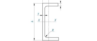
Detail elements
If part of a detail drawing needs to be displayed in more detail than the selected scale of the main drawing allows, so-called callout elements are used.
The location of the extension element in the main view is indicated by a closed contour, most often round or oval. From there there is a thin arrow leading to the placement of a detailed image. If such a line is not drawn, the letter designation of the element is written above the extension line, and the letter is repeated above the detailed drawing.
Sometimes the callout element may differ from the type of the main image. Display in the form of sections, cuts, etc. is allowed.
The location of the extension element indicates detailed linear and angular dimensions, information about accuracy, quality and roughness, as well as other necessary information.
Conventions and simplifications
To make drawings easier to read and understand, it is allowed to depict a part on them that is not 100% in accordance with the actual shape, using the following conventions and simplifications:
- For parts that have a central axis of symmetry, it is allowed to draw half the contour. As a rule, an incision or section is placed in the location of the second half.
- If the design includes several identical elements, one of them is displayed in detail, with dimensions and tolerances; the location of others is simplified in the form of contours or their number is simply indicated.
- The transition between surfaces can be reflected conditionally or omitted altogether.
- Fastening parts, spherical elements, shafts, handles, etc. on longitudinal sections they are drawn without dissection.
- For thin-walled parts, an image on an enlarged relative to the general scale is allowed.
- For greater clarity, it is permissible to increase the angle of the cone or slope.
- The flat edges of the part are highlighted with diagonal thin lines.
- Parts of long length with an unchanged profile are depicted with a gap, marking its places with broken or wavy lines.
- The knurling or notch may be partially depicted.
In some specific cases, additional simplifications are applied. Acceptable conventions in the arrangement of certain types of drawings, such as gears, electronic components and devices, etc., are described in the relevant standards.
When simplifying a drawing, the designer should take precautions so that the document that comes out from under his mouse does not turn into a puzzle that will take his partners a lot of time to solve.
3.2. Applying dimensions
In the drawings of parts, dimensions are indicated based on the manufacturing technology of the part and the surfaces on which the part comes into contact with other parts of the assembly unit.
This affects the choice of design base.
Based is the process of giving the workpiece the required position relative to the selected coordinate system.
A base is a surface or combination of surfaces, an axis or a point belonging to a product or workpiece and used for basing.
Design base - a base used to determine the position of a part or assembly unit in a product.
The basic rule for applying dimensions is to group dimensions related to one geometric element in one image, in the one in which this element is most clearly represented. It is not always possible to achieve this, but we always strive for this.
When indicating the size of an angle, the dimension line is drawn in the form of an arc with the center at its vertex, and the extension lines are drawn radially (Figure 3.2).
| Figure 3.1 | Figure 3.2 |
It is preferable to apply dimension lines outside the outline of the image. The use of contour lines, axial, center and extension lines as dimension lines is not allowed. The intersection of dimension and extension lines, shown in the crossed out Figure 3.3, a, is unacceptable. The correct dimensions for this case are shown in Figure 3.3, b.
| A | b |
As you can see, smaller dimensions should be placed closer to the contour of the part; the number of intersections of dimension and extension lines will be reduced, which will make the drawing easier to read.
The dimension line is drawn with a break if it is not possible to draw an extension line on one side of the image, for example, in the case of combining a view and a section (Figure 3.4, a), and also if the view or section of a symmetrical object is depicted only to the axis or with a break (Figure 3.4, b). The break of the dimension line is made further than the axis or break line of the object.
Read also: Make a stand for an eye-machine with your own hands
| A | b |
Dimension lines may be drawn with breaks in the following cases:
- when indicating the size of the circle diameter; in this case, the break of the dimension line is made further than the center of the circle (Figure 3.5);
- when drawing dimensions from a base not shown in this drawing (Figure 3.6).
| Figure 3.5 | Figure 3.6 |
The main line must be broken if it intersects with the arrow (Figure 3.5).
When depicting a product with a gap, the dimension line is not interrupted (Figure 3.7). The dimensional number must correspond to the full length of the part.
Figure 3.7
If it is not possible to place dimensional numbers and arrows between closely spaced solid main or thin lines, they are applied outside (Figure 3.8). Do the same when applying the radius size if the arrow does not fit between the curve and the center of the radius (Figure 3.9).
| Figure 3.8 | Figure 3.9 |
It is allowed to replace arrows with dots or serifs, applied at an angle of 45° to the dimension lines, if it is impossible to place an arrow between the extension lines (Figure 3.10).
Figure 3.10
Dimensional numbers must not be divided or crossed by any drawing lines. At the place where the dimension number is applied, the axial, center lines or hatch lines are interrupted (Figure 3.11).
Figure 3.11
Dimension numbers should be placed above the dimension line, as close to its middle as possible (Figure 3.12).
Figure 3.12
Dimensional numbers of linear dimensions with different slopes of dimension lines are placed as shown in Figure 3.13.
If it is necessary to apply dimensions to the shaded area, the corresponding dimensional number is applied on the shelf of the line - leader.
Figure 3.13 Angular dimensions are applied as shown in Figure 3.14.
Figure 3.14
In the area located above the horizontal center line, dimensional numbers are placed above the dimension lines on the side of their convexity, in the area located below the horizontal center line - on the concavity side of the dimension line.
Dimension numbers above parallel dimension lines should be placed in a checkerboard pattern (Figure 3.15).
Figure 3.15
When indicating the diameter size, in all cases the sign ? is placed before the size number. Before the dimensional number of the diameter (radius) of the sphere, the sign “O” is also applied? (R) without the inscription “Sphere” (Figure 3.16).
Figure 3.16 If it is difficult to distinguish a sphere from other surfaces in a drawing, it is allowed to write the word “Sphere” or the sign “O”, for example, “Sphere? 18, OR12." The diameter of the sphere sign is equal to the height of the dimensional numbers in the drawing. The dimensions of the square are applied as shown in the drawing (Figure 3.17). Figure 3.17
The height of the sign must be equal to the height of the dimensional numbers in the drawing.
When applying a radius size, place a capital letter R in front of the size number. With a larger radius, the center can be brought closer to the arc; in this case, the radius dimension line is shown with a bend at an angle of 90° (Figure 3.18). If it is not necessary to indicate the dimensions that determine the position of the center of the circular arc, then the radius dimension line may not be brought to the center and may be shifted relative to the center (Figure 3.19).
| Figure 3.18 | Figure 3.19 |
Rounding radii, the size of which on the drawing scale is 1 mm or less, are not shown in the drawing and their dimensions are indicated as shown in Figure 3.20. When applying the size of a circular arc, the dimension line is drawn concentrically to the arc, and the extension lines are parallel to the bisector of the angle, and the sign “” is placed above the dimension number (Figure 3.21).
| Figure 3.20 | Figure 3.21 |
The dimensions of the chamfers at an angle of 45° are applied as shown in Figure 3.22, a. It is allowed to chamfer at an angle of 45°, the size of which on the scale of the drawing is 1 mm or less, not to be depicted and its dimensions to be indicated on the shelf of the leader line, as shown in Figure 3.22, b.
The dimensions of chamfers with other angles are applied according to the general rules - two linear dimensions or linear and angular dimensions (Figure 3.23).
The question of what dimensions should be plotted on the drawing is decided taking into account the manufacturing technology of the parts and manufacturing control.
As a rule, the dimensions of complete circles are given by the diameter, and of partial circles by the radius.
When you need to set the distances between circles, for example, representing holes, set the distances between the centers of the circles and the distance from the center of any circle to one of the surfaces of the part.
| A | b |
Figure 3.22
Figure 3.23 The surfaces from which the dimensions of other elements of the part are set are called base surfaces or bases. There are several ways to apply dimensions:
- from the total base (Figure 3.24); The left surface of the strip is selected as the base surface, from which the dimensions of all holes are assigned.
Read also: Operating principle of a digital voltmeter
Such a system has an advantage, but the dimensions are independent of each other, the error of one of them does not affect the others.
- from several bases (Figure 3.25);
- chain (Figure 3.26).
Figure 3.24
When applying dimensions that determine the distance between evenly spaced identical elements of a product (for example, holes), it is recommended, instead of dimensional chains, to apply the size between adjacent elements and the size between extreme elements in the form of the product of the number of spaces between the elements and the size of the space (Figure 3.27).
With a large number of dimensions applied from a common base, it is allowed to apply linear and angular dimensions, as shown in Figure 3.28, while drawing a common dimension line from o and dimension numbers are applied in the direction of the extension lines at their ends.
Figure 3.27
Figure 3.28
It is allowed not to indicate on the drawing the dimensions of the conjugation radius of parallel lines (Figure 3.29). Figure 3.29
The external and internal contours of parts are measured separately during manufacturing and inspection, so their dimensions should be plotted separately on the drawing (Figure 3.30).
Figure 3.30
It is recommended to group dimensions related to the same structural element (groove, protrusion, hole, etc.) in one place, placing them in the image in which the geometric shape of this element is shown most fully (Figure 3.31).
Figure 3.31 If a part has roundings, the dimensions of the parts of the part are applied without taking into account the roundings, indicating the radii of the roundings (Figure 3.32). Figure 3.32
The dimensions of symmetrically located elements of the product (except for holes) are applied once without indicating their number, grouping, as a rule, all dimensions in one place (Figure 3.33).
Figure 3.33
Identical elements located in different parts of the product (for example, holes) are considered as one element if there is no gap between them (Figure 3.34, a) or if these elements are connected by thin solid lines (Figure 3.34, b). In the absence of these conditions, indicate the full number of elements (Figure 3.34, c).
| A | b | V |
Figure 3.34 The dimensions of several identical elements of the product, as a rule, are applied once, with a line indicating the number of these elements on the shelf (Figure 3.35).
Figure 3.35
When applying the dimensions of elements evenly spaced around the circumference (for example, holes), instead of the angular dimensions that determine the relative position of the elements, only their number is indicated (Figure 3.36 - 3.38).
| Figure 3.36 | Figure 3.37 | Figure 3.38 |
When depicting a part in one projection, the size of its thickness or length is applied, as shown in Figure 3.39.
Figure 3.39 Dimensions on the drawing are not allowed to be drawn in the form of a closed chain, except in cases where one of the dimensions is indicated as a reference. Reference dimensions – dimensions that are not subject to execution according to this drawing and are indicated for greater ease of use of the drawing.
Reference dimensions are on the drawing, and in the technical requirements write “* Dimensions for reference”. If all the dimensions in the drawing are for reference, they are not marked with the “*” sign, and “Dimensions for reference” are written in the technical requirements.
Reference sizes include the following sizes:
- one of the sizes of a closed dimensional chain (Figure 3.40);
- dimensions transferred from drawings - blanks (Figure 3.41);
- dimensions that determine the position of part elements to be processed on another part (Figure 3.42);
Figure 3.40 Figure 3.41
Figure 3.42
- dimensions on the assembly drawing, which determine the limiting positions of individual structural elements, for example, piston stroke, valve rod stroke of an internal combustion engine, etc.;
- dimensions on the assembly drawing, parts transferred from the drawing and used as installation and connecting parts;
- overall dimensions on the assembly drawing, transferred from the drawings of parts or being the sum of the dimensions of several parts;
- dimensions of parts (elements) made of long, shaped, sheet and other rolled products, if they are fully determined by the designation of the material given in the corresponding column of the main inscription (Figure 3.43).
Figure 3.43 Notes:
- Installation and connecting dimensions are dimensions that determine the dimensions of the elements by which this product is installed at the installation site or connected to another product.
- Dimensions are dimensions that determine the maximum external (or internal) contours of the product.
All images are accompanied by dimensions. When applying dimensions, you should be guided by the basic provisions of GOST 2.307-2011 “Applying dimensions and maximum deviations”.
The basis for determining the size of the depicted product and its elements are the dimensional numbers indicated in the graphic document. The numerical value of the size entered must correspond to its natural size (actual value), regardless of the accepted image scale. On training drawings only nominal dimensions are indicated without indicating their maximum deviations.
Read also: How to tin aluminum at home
Linear dimensions are indicated on the drawing in millimeters without indicating a unit of measurement, angular dimensions - in degrees, minutes.
Dimensions in graphic documents are indicated by dimensional numbers and dimension lines.
When applying the size of a straight segment, the dimension line is drawn parallel to this segment, extension lines are drawn perpendicular to the dimension lines (Fig. 7).
Rice. 7. Rules for placing dimensions in the drawing
It is preferable to apply dimension lines outside the outline of the image. It is not allowed to use contour lines, axial, center and extension lines as dimension lines. It is necessary to avoid intersections of dimension and extension lines. The dimension line is limited at both ends by arrows resting on the extension lines. The shape of the arrow and the approximate ratio of the sizes of its elements are shown in Fig. 8.
Rice. 8. Image of arrows in the drawing
Extension lines are drawn from the visible contour lines. Extension lines should extend beyond the ends of the arrows of the dimension line by 1...5 mm.
The distance between the contour line and the dimension line is selected depending on the size of the image and the saturation of the drawing. The minimum distance between the dimension line and the contour line should be 10 mm, and the minimum distance between parallel dimension lines should be 7 mm.
Dimensional numbers are applied above the dimension line, as close as possible to its middle. When drawing several parallel dimension lines, the dimension numbers should be placed in a checkerboard pattern (Fig. 7).
If there is not enough space to apply arrows and dimensional numbers, then they are applied using one of the methods shown in Fig. 9. If there is not enough space for arrows on dimension lines located in a chain, arrows can be replaced with serifs 1-3 mm long, applied at an angle of 45° to the dimension lines or clearly marked dots (Fig. 9). If there is not enough space for the arrow due to a closely located contour or extension line, the latter can be interrupted.
Rice. 9. Dimensional lines
Dimensional numbers are not allowed to be divided or crossed by any drawing lines. At the place where the dimensional number is applied, the axial, center lines and hatch lines are interrupted (Fig. 10).
It is recommended to group dimensions related to the same structural element (groove, protrusion, hole, etc.) in one place, placing them on the image in which the geometric shape of this element is shown most fully (Fig. 11).
Rice. 11. Grouping sizes
When plotting the size of the arcs, indicate its radius; for a circle, its diameter. R ” is placed in front of the radius dimensional number.
, (for example,
R 20
), before the diameter dimensional number there is a sign “” (for example,
20
).
In the case of an image of a part with a spherical surface, if it is difficult to distinguish it from other surfaces, it is allowed to apply the word “Sphere” or the sign “” when applying the size of the diameter (radius) of the sphere (for example, Sphere
R 15 or
40
).
A square in the drawing is defined by two sizes of its sides or one size with the sign “” (Fig. 12). Diagonals on the edge of an element, drawn by thin lines, conventionally indicate a plane.
The dimensions of the chamfers at an angle of 45º are applied as shown in Figure 12 a
. The chamfer width and angle are combined into one dimension using the “×” sign.
The dimensions of chamfers at other angles are indicated separately by linear and angular dimensions (in Fig. 12 a
This is how the chamfer dimensions are indicated at an angle of 30º with a chamfer width of 3 mm) or two linear dimensions (Fig. 12
b
).
If a view or section of a symmetrical object or individual symmetrically located elements is depicted only up to the axis of symmetry or with a break, then the dimension lines related to these elements are drawn with a break, and the break of the dimension line is made further than the axis or break line of the object (Fig. 13).
Rice. 13. Dimensioning with a break
The total number of sizes should be minimal, but sufficient for the manufacture and control of the product. The dimensions of the same element in the drawing are not allowed to be repeated. The dimensions of several identical elements of the product, as a rule, are applied once, indicating the number of these elements on the shelf or under it (Fig. 14). At the same time, for elements evenly spaced around the circle (for example, holes), angular dimensions are not placed between them, provided that one of these elements lies on one of the axes of symmetry (Fig. 14 a
).
Only the size of the diameter of the circle on which the centers of the holes are located in Fig. is indicated. 14 a
.
If none of the holes lies on the axis of symmetry, then you should set the angle to the first element (Fig. 14 b
).
Applying dimensions
The standard and most often used are roundings made at an angle of 45 degrees. Therefore, if the exact value is not shown in the drawing, this particular slope is implied. Otherwise, when a different angle, such as 30 degrees, is to be used, a similar feature must be specified. This can be done in the same ways - using an extension line, as well as using linear dimensional symbols.
The presence in the drawing of 2 chamfers, which are located symmetrically and at the same diameter, requires indicating their size without additional notes. But if the application diameter is different (for example, the object is a cone or cylinders of different radii), it is necessary to indicate their exact number. It is worth considering that the bevels on the internal and external surfaces are summed up separately, even when their values are the same. In the case where the part has a regularly varying diameter, it is possible to use breaks so as not to complicate the drawing. In this case, the chamfer dimensions are drawn in the usual way; only the wavy line is taken into account, which cannot be used functionally, since it determines the missing distance.
The following solution is possible: the same parameters for all are indicated in the description under a digital designation (1, 2, 3, etc.), and only the reference number in the description is transferred directly to the drawing. As a result, there is no need to set the size in each individual case. However, it is worth remembering that an identical value that appears in other places must be denoted by the same number, even if it refers to a different page.
In many industries, for processing wood, steel and other materials, machine complexes are used, into which drawings are automatically stored. In these cases, to ensure safety and better contact with adjacent components and parts, chamfers are provided in advance. Depending on the type of production, thermal or mechanical effects are possible, which cannot be replaced by manual labor
Therefore, it is extremely important to carry out the technical drawing thoughtfully, not forgetting to indicate the exact numerical designations of the chamfers, as well as their number
If you find an error, please select a piece of text and press Ctrl+Enter.
Bevel shapes
The method of designing the end surfaces depends not only on the thickness of the parts, but also on the load on the welding seam. The configuration of the edges determines the size of the thermal action zone, the shape of the seam bead, the intensity of heating and other parameters that affect the strength of the joint.
V-shaped
This bevel is the most common way to design the ends of parts. It is used when welding metal sheets with a thickness of 3 to 60 mm. For critical structures, the size limits are 3-26 mm.
The angle depends on the number of processed edges. Its cutting is one-sided, then the chamfer is made at 50°, if double-sided - at 60°.
A V-shaped bevel is the most common way to design the ends of parts.
K-shape
Cutting is used for thick-walled parts that are connected end-to-end or at right angles. With this type of design, bevels are made only on one of the edges, but on both sides.
The K-bevel is made on only one of the edges on both sides.
The chamfer angle is selected depending on the welding machine:
- with manual gas-flame equipment - 40-45°;
- with electric arc - 30-35°.
The free edges are blunted to a height of 1-3 mm. Insufficient preparation of the edge can lead to burn-through of the seam, and excessive preparation can lead to lack of penetration.
U-shaped
Curvilinear (U-shaped) cutting allows you to save electrodes, ensure uniform boiling and speed up the process. The heat-affected zone with this method of finishing the ends is smaller than with V-shaped cutting, so the connection is more durable.
Curvilinear chamfers are made on workpieces with a thickness of 20-60 mm. Depending on the size and purpose of the part, cutting is performed on one or both sides.
The U-shaped bevel saves electrodes and speeds up the work process.
X-shaped
This cutting is carried out with a double-sided connection and a large thickness of the workpieces. In the vertical plane, it consists of V-shaped bevels made on each side of the parts. Thanks to the large volume of the weld pool and access to the root of the seam, the finished joint is capable of operating under heavy loads.
X-shaped seam cutting is carried out with a double-sided connection and a large thickness of the workpieces.
Seam beads with X-shaped edges are wider than with U-shaped edges. The seams are fused in layers.
The recommended cutting angle is 45 or 60°. The more viscous the metal remains when exposed to high temperatures, the larger the bevel parameter is chosen when preparing the edges.
Symbols for seams with edge cutting.