Rules for drawing up drawings according to ESKD
When preparing drawings, pay attention to 5 main points:
- sheet format;
- lines;
- size;
- font.
scale;
Sheet format and design
The design of the sheet is regulated by GOST 2.301-68. Drawings are drawn up on A4 sheets - 297*210 cm. Parameters of other formats are specified in GOST.
Requirements for sheet format according to GOST
First, a frame is drawn on the sheet that defines the boundaries. It is designed with solid thick lines. On the left, a distance of 20 mm is maintained for hemming. To the right from the outer edge to the frame - a distance of 5 mm.
Information is indicated at the bottom right. Solid thick lines are used for graphs.
Example of frame and information design
Main inscription
The title block is required for drawings of all scales. It is regulated by GOST 2.104-2006. The main inscription is located at the bottom right. Solid thick lines are used for graphs.
The following information is indicated in the columns:
- the name of the product in the nominative singular case, for example “Wheel”, if the name of the product consists of several words, then the noun “Geared Wheel” is put in first place;
- designation of the drawing according to GOST 2.201-80. For example, UZ.KCH0115.000. UZ - educational institution, KCh0115 - drawing course, task one, option fifteen, 000 - serial number of the part
- designation of the part material;
- letter assigned to the document (letter U);
- product weight in kg;
- scale
- serial number of the sheet;
- the total number of worksheets completed during the semester;
- study group number;
- nature of the work;
- last name of the student and teacher;
- signatures;
- date of signing of the drawing.
Example of title block design
Scale
Scale is the ratio of the image sizes in the drawing to the actual dimensions of the product. To draw products with non-standard sizes, the rule is used: large ones are reduced, small ones are increased.
The following types of scale are distinguished:
- Life size is rare - 1:1. The most convenient, as the size of the product is immediately clear.
- Reduction scale - 1:2; 1:2.5, etc. Used for large products, for example, aircraft parts.
- Magnification scale - 2:1; 2.5:1, etc. Used to depict a small product, for example, a part for a watch mechanism.
- Particular scales of reduction are calculated using special formulas. Used by architects to depict very large objects, such as bridges.
- Specific magnification scales are calculated using the formula. Used for microscopic parts.
GOST 2.303-68 will help you calculate the scale. Indicate the scale in a special field in the frame.
If you are not sure that you can handle the job yourself, contact a professional. We will deliver the work ahead of schedule or return 100% of the money
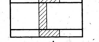
Often the drawing shows details of different scales. This happens when it is necessary to demonstrate the design features of a product. For this purpose, cuts, sections, and extension elements are used.
They are smaller in size than the main part, which means the scale is different. It is indicated next to the element by placing the letter M in front of the numbers - M 1:1; M 1:2; M 2:1.
An example of indicating the scale in a drawing
Lines
For the drawing, lines of different thicknesses are used. There are 6 types in total. Regulated by GOST 2.303-68. The line type is selected depending on the work format.
- Solid thick main is used to indicate outlines, frames and graphs of the title block.
- Dashed lines show invisible contours. The dashed lines should be the same size, and the space between them should be the same in length.
- A thin dotted line draws the axis of symmetry. It shows the axes of rotation, the center of circular arcs.
- Extension and dimension lines with a thickness of s/3-s/2 are drawn in solid thin
- A dotted line + 2 thin dots indicate the fold lines.
- Solid wavy indicates a break when the image is too large to fit on one sheet.
Types and characteristics of lines for drawings
Dimensions
Dimensions are needed to determine the dimensions of the product. Angular dimensions describe the size of an angle in degrees, seconds, minutes. The unit of measurement is indicated.
Linear - length, width, height, diameter, thickness and radius of a part of the product. These figures are indicated in mm. The unit of measurement is not specified.
Attention! Regardless of the scale, product dimensions are indicated in actual size. Specifying a size that has changed as a result of scaling is considered an error.
An example of specifying dimensions in a drawing
Font
The drawings use a special drawing font with regulated parameters for letters, numbers (size, angle) and the distance between words.
Quality
Quality (in Russian from German Qualität, which from Latin qualitas - quality) is a characteristic of the manufacturing accuracy of a product (part), which determines the tolerance values.
Quality is a measure of accuracy. As quality increases, tolerance increases and accuracy decreases.
- Qualification tolerance is indicated by the letters IT
indicating the qualification number, for example IT8 - tolerance for the 8th qualification. Qualities from 01 to 4 are used for the manufacture of calibers and counter-calibers. - Qualities from 5th to 12th are used for the manufacture of parts that form mates - the relative positions of the component parts of the product, characterized by the contact of their surfaces or the gap between them, specified by the design documentation. An example of such conjugations can be GCS - smooth cylindrical connections).
- Qualities from 13 to 17 are used for parameters of parts that do not form mates and do not have a decisive influence.
=
International tolerance
),
- IT
, µm =
K * i
,
is quality (number of tolerance units),
i
is tolerance unit, µm.
Tolerance values for main hole sizes up to 500 mm:
| Size, mm | Tolerance, microns, with quality | ||||||||||||||||||
| 01 | 1 | 2 | 3 | 4 | 5 | 6 | 7 | 8 | 9 | 10 | 11 | 12 | 13 | 14 | 15 | 16 | 17 | ||
| Until 3 | 0,3 | 0,5 | 0,8 | 1,2 | 2 | 3 | 4 | 6 | 10 | 14 | 25 | 40 | 60 | 100 | 140 | 250 | 400 | 600 | 1000 |
| 3—6 | 0,4 | 0,6 | 1 | 1,5 | 2,5 | 4 | 5 | 8 | 12 | 18 | 30 | 48 | 75 | 120 | 180 | 300 | 480 | 750 | 1200 |
| 6—10 | 0,4 | 0,6 | 1 | 1,5 | 2,5 | 4 | 6 | 9 | 15 | 22 | 36 | 58 | 90 | 150 | 220 | 360 | 580 | 900 | 1500 |
| 10—18 | 0,5 | 0,8 | 1,2 | 2 | 3 | 5 | 8 | 11 | 18 | 27 | 43 | 70 | 110 | 180 | 270 | 430 | 700 | 1100 | 1800 |
| 18—30 | 0,6 | 1 | 1,5 | 2,5 | 4 | 6 | 9 | 12 | 21 | 33 | 52 | 84 | 130 | 210 | 330 | 520 | 840 | 1300 | 2100 |
| 30—50 | 0,6 | 1 | 1,5 | 2,5 | 4 | 7 | 11 | 16 | 25 | 39 | 62 | 100 | 160 | 250 | 390 | 620 | 1000 | 1600 | 2500 |
| 50—80 | 0,8 | 1,5 | 2 | 3 | 5 | 8 | 13 | 19 | 30 | 46 | 74 | 120 | 190 | 300 | 460 | 740 | 1200 | 1900 | 3000 |
| 80—120 | 1 | 1,5 | 2,5 | 4 | 6 | 10 | 15 | 22 | 35 | 54 | 87 | 140 | 220 | 350 | 540 | 870 | 1400 | 2200 | 3500 |
| 120—180 | 1,2 | 2 | 3,5 | 5 | 8 | 12 | 18 | 25 | 40 | 63 | 100 | 160 | 250 | 400 | 630 | 1000 | 1600 | 2500 | 4000 |
| 180—250 | 2 | 3 | 4,5 | 7 | 10 | 14 | 20 | 29 | 46 | 72 | 115 | 185 | 290 | 460 | 720 | 1150 | 1850 | 2900 | 4600 |
| 250—315 | 2,5 | 4 | 6 | 8 | 12 | 16 | 23 | 32 | 52 | 81 | 130 | 210 | 320 | 520 | 810 | 1300 | 2100 | 3200 | 5200 |
| 315—400 | 3 | 5 | 7 | 9 | 13 | 18 | 25 | 36 | 57 | 89 | 140 | 230 | 360 | 570 | 890 | 1400 | 2300 | 3600 | 5700 |
| 400—500 | 4 | 6 | 8 | 10 | 15 | 20 | 27 | 40 | 63 | 97 | 155 | 250 | 400 | 630 | 970 | 1550 | 2500 | 4000 | 6300 |
Thread symbol
Each type of thread that was described above is regulated by a separate GOST. Let's figure out what is encrypted in general.
- a carving mark indicated by a letter;
- nominal size, expressed in inches or mm;
- step indicator;
- if the thread is multi-start, then the stroke indicator and its pitch are indicated;
- in the case of a left-hand thread, LH is added;
- tolerance range (numeric-alphabetic) and accuracy class (alphabetic);
- make-up length (if different from the standard) - letter or number.
Features of thread designation
Due to the fact that the shape of the threaded surface is quite complex, and the connection itself is rarely used, in order to simplify the process of creating design documentation, a symbol was introduced for this complex profile.
Features of the symbol include:
- the use of a thin line extending into the hatching. The type of connection and diametrical section are indicated on the extension dimension line;
- symbol of a thread may be necessary if you need to display a profile, in particular, the angle between individual turns;
- If the product is of high precision, the dimensional tolerance must be indicated. This is done using an extension shelf or a dimension line;
- The creation of high-quality fasteners is accompanied by monitoring the roughness of the resulting surface.
Countersink designation in the drawing
- d1 – indicates the main diameter of the channel;
- d2 – for countersinking diameter;
- L1 – displays the length of the cylindrical channel;
- L3 is the countersinking depth;
- L4 – indicates the depth of the chamfer;
- j is the size of the central countersinking angle;
- α (alpha) – chamfer angle size.
Dear site visitors: mechanical engineers, craftsmen and those simply familiar with the topic, support the discussion in the comments! Your professional comments are very important to us.
Requirements for the execution of detailed drawings of printed circuit boards
Designation of drawings
All detailed drawings of single-layer, double-layer and multilayer printed circuit boards must have the name “Printed Board” in the designation of the drawing.
Applying dimensions
All necessary dimensions on the drawings must be drawn in accordance with GOST 2.307.
The following methods of specifying the dimensions of structural elements of printed circuit boards are allowed:
- using coordinate grids - polar or rectangular;
- combination of coordinate grid and extension dimensions;
- in a tabular manner indicating the coordinates of the elements of the conductive pattern (mounting and via holes, grooves, contact pads, conductors).
Coordinate grid on detailed drawings of printed circuit boards
Grid lines must be numbered. The grid pitch in each specific case of performing a detailed drawing of a printed circuit board should be selected depending on the saturation of the conductive pattern.
According to GOST, it can be expressed both by the number of grid lines and in millimeters.
The pitch of the coordinate grid, made in a rectangular coordinate system, must comply with GOST 10317.
Based on the features of the design documentation being developed, the following methods of applying coordinate grids are allowed:
- to the entire field of the detailed drawing;
- on a printed circuit board or its individual elements;
- applying coordinate grid marks along the contour of the printed circuit board;
- drawing marks of a coordinate grid at a certain distance from the contour of the printed circuit board.
Origin of the rectangular coordinate system
When making detailed drawings of printed circuit boards, characteristic lower left or right structural elements are usually chosen as the origin in a rectangular coordinate system:
- PCB outline boundaries;
- center of the outer hole;
- points formed by the intersection of construction lines.
For round printed circuit boards, the points formed by the intersection of tangents to the circle are taken as the origin. Also, it is allowed to take the center of a round printed circuit board as the reference point.
Designation and dimensions of contact pads
In detailed drawings of printed circuit boards, pads with through holes are depicted as a single circle. The same applies to holes with countersinks.
In justified cases, it is allowed to depict contact pads with geometric shapes other than circles (square, rhombus, polygon).
To ensure that contact pads and holes that are similar in size are different from each other, each of the corresponding holes should be indicated by a symbol (according to GOST 2.307).
The corresponding summary information about the symbols of holes in detailed drawings of printed circuit boards is entered into a table where the following is indicated:
- symbol of holes;
- contact pad shape;
- hole diameter;
- dimensions of the contact pad;
- presence of metallization in the hole;
- number of holes.
Other requirements
On the image of a printed circuit board in a detailed drawing, it is allowed to include information that may not be physically present on the product itself. In this case, a corresponding entry must be made in the technical requirements of the detailed drawing. If the coordinate grid interferes with making a record, it is allowed not to make it in this place.
The drawing may be missing some information about individual elements of the printed circuit board. In this case, the technical requirements must contain a link to a document containing the necessary information.
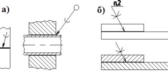
Maximum deviations in the dimensions of assembled parts
It is customary, according to the current rules, to indicate those maximum dimensional deviations that the parts indicated on the assembly drawings have in the form of fractional numbers. In this case, their denominators contain symbols of the shaft tolerance field, and their numerators contain symbols of the hole tolerance field. For example:
Such designations are extremely widespread in technology, since without their use it turns out to be very difficult to assemble various devices, machines and mechanisms that have a rather complex design and consist of a considerable number of parts.
Maximum deviations of the dimensions of parts in the form of fractions
Maximum deviations of hole and shaft dimensions
Maximum deviations in the dimensions of assembled parts
In many cases, those maximum dimensional deviations that the parts shown on the assembly drawings have are indicated in the form of records. Moreover, they are designated only for one of those parts that are paired. In such cases, the drafters must necessarily explain which part of those shown on the assembly drawing the indicated deviations relate to.
Maximum deviations in the dimensions of assembled parts with explanations